1
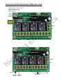
RSD H2 TLM4 Universal Remote Control Switch & Receiver AC/DC load 12VDC 12A 150m Applications Ideal for Remote control multiple 4 independent channels (AC, DC loads can be mixed) Multiple garage doors, lights, electrical appliance, pumps, caravans, and motors Can be used as alternative of latching or hold relay, SPST, DPDT switch or remote trigger point of PLC control Specifications tr on ic s RSD H2 TLM4 12VDC ≤ 7 mA 20A14VDC; 20A125VAC (able to drive a heavier load IF combined with Air Breaker) 315 MHz Up to 150 m in clear area 4 Universal “T “or “L” or “M” type T Type Self‐Locking contact A contact holds until press same remote button again 4 channels works independently A contact holds accordingly after press associated remote button. The contact will be release once any other button pressed. 4 channels latch each other Only one channel can be on at any time ec Model: Power Supply: Static Current: Contact Rate: Remote Frequency: Remote Distance: Control Channel: Control Type: ht el L type M Type A contact holds only during its remote button is pressed and holed 4 channels works independently gh lig Control Type Selection: The control type can be pre‐selected by a jumper (JP2) BEFORE power on. Code learning: To learn a new remote or remote with new communication code, press the code learning button (S1) till LED light on, release S1 then press any button on new remote in 5 seconds, LED will flash three times. The code learning is finished. Try the remote. hi External Dimension: Approx 80L* 55W*28H mm (Main box with case); Approx 60L*40W*15H mm (Remote) Remote Battery: 23A 12V DC battery included Warranty: 12 month Contents Including: One Receiver with case (12VDC, 4 Channels) One Remote (315 MHz, 23A 12V battery, Up to 150 m) User manual Terminals and Wiring Example (Reference only) Control type selection: JP2 (Prior Power On) 1. Left Pin & Middle Pin: M type 2.Middle Pin & Right Pin: T type 3. Empty Pins: L type Code Learning Button S1 s www.highlightelectronics.com.au on ic Max Contact: 20A 14VDC 20A 125VAC +12VDC NO NO NC C NC Ch B Ch A NO C NC Ch C NO C NC Ch D el C ec tr 0VC gh lig ht hi www.highlightelectronics.com.au +12VDC 0VC DC Load AC Load Switched Switched L Line N Line 12VDC Load How to setup a unique communication code between a remote and main unit: s 7. 8. 9. 10. 11. 12. Make sure the pin combinations of remote is unique Make sure the power supply to the unit is correct Found the code learning button (labelled S1, next to the negative terminal of 12VDC power supply) Allocate a pair of main unit and the remote Power on the main unit, a red led on the main unit will be on and stays Press the S1 (a green LED will be on) and hold till the green LED flashes which means the previous code stored in the main unit is cleared (empty) now which means is ready to hold a new code Wait a few seconds Press the S1 button shortly (a green LED will be on and stays) then release the S1 button Press any button of the associated remote and the green LED will flashes a few times Wait a few seconds Try the pair of main unit and remote Repeat step 5 and 10 if not success on ic 1. 2. 3. 4. 5. 6. ec tr Demo Combination: Pin 1 joins to H, Pin 3 to L, Pin 7 to H. Others remain opened. L ht H el www.highlightelectronics.com.au gh lig www.highlightelectronics.com.au Front View of Remote Board hi The product is made in China