1
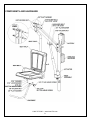
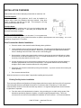
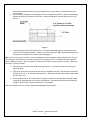
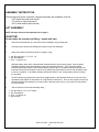
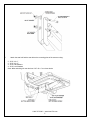
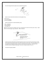
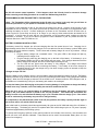
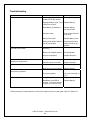
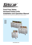
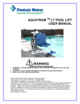
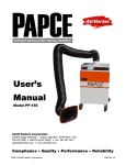
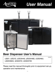
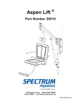
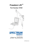
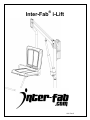
® Inter-Fab i-Lift i-Lift Rev G You have purchased an i-Lift assisted access lift. Providing the unit is installed correctly and properly maintained, it will furnish you with many years of trouble free use. It is important to read this entire manual prior to beginning assembly or operation. Shipping Information: Each lift will arrive partially assembled in one box. Before accepting the lift from the carrier, inspect for visible damage and match the contents with those listed below. Inter-Fab is not responsible for lost or damaged freight. The box will contain all structural components and hardware. The following is a list of the components included with your shipment from Inter-Fab. Use Components and Hardware Figure, page 3, as a reference to identify each item listed. 1 1 1 1 1 1 Mast & Boom assembly Actuator Seat Belt Seat pole assembly Charger General hardware 2 1 1 1 1 Seat Halves Footrest assembly Battery Wireless Transmitter Anchor Assembly 1.800.737.5386 • www.Inter-Fab.com 2 COMPONENTS AND HARDWARE 1.800.737.5386 • www.Inter-Fab.com 3 INSTALLATION OVERVIEW Read all instructions before attempting to assemble or install the i-Lift . Clear Deck Space: To be compliant with ADA guidelines, the lift must be installed in a location that is clear from obstacles and other hazards. Clear deck space is defined by the figure to the right. This rectangle is 48” long (along the pool wall) and 36” wide. Pool/Spa Depth: To comply with ADA guidelines the i-Lift must be installed where the water depth does not exceed 48”. If the entire pool is deeper than 48" this requirement does not apply. Anchor Location/Installation: The i-Lift anchor centerline must be no less than 6”, but no greater than 22” from the pool/spa wall (or any feature that sticks out past the pool/spa wall, such as a coping). The i-Lift is installed in a single 2.375” I.D. anchor. New Construction Anchor Installation a. Place the anchor in the desired location following above guidelines. b. Locate a bonding source to bond (ground) the anchor. The steel rebar-bonding grid of the pool deck is the best choice for bonding the anchor. Attach a No. 8 solid copper wire (NEC Section 680-22) from the bonding bolt on the base of the anchor to the bonding grid. c. Secure anchor in place at the proper height –cement or epoxy may be used to hold anchor in place. Set the anchor so that the finished top is 1/8” to 1/4” below finished deck level – allowing for anchor cap to be put in place when the lift is not in use. d. Use the carpenter’s level to level the anchor making sure the i-Lift mast will be vertically straight up and down (perpendicular to the deck) in all directions. It is important that the mast be vertically straight to ensure ease of rotation when the lift is fully loaded. e. Place tape over the anchor hole before pouring concrete deck – to prevent concrete from entering the anchor opening. f. Pour concrete deck and finish. Allow the concrete to cure for at least 7-days before installing and using the lift. Existing Facility Anchor Installation There are many different configurations of footing shapes and sizes to resolve the forces of the lift; a general case footing that has been calculated for Spectrum is a minimum slab 2’6” Square by 10” thick anchor centered, with a minimum of four #4 bars each way centered. An engineer stamped letter can be furnished by Spectrum if requested. a. From the center of the desired anchor location, using a marking pen or chalk, mark a square of the dimensions provided by Spectrum Aquatics, or another engineer stamped footing. This is the concrete to be removed to accommodate the installation of the lift’s anchor. It is recommended that 1.800.737.5386 • www.Inter-Fab.com 4 the anchor be located at least 6” from any expansion joint, crack, drain, or similar structure in the concrete deck. b. Use a concrete cutting saw; cut the square out of the existing concrete deck. Using a heavy/sledge hammer to break the cut section of concrete – remove the section of concrete from the deck. See Figure 1. 2’-6” Square x 10” thick 4 #4 bar centered each way 10” Thick Figure 1 c. Locate a bonding source to bond the anchor. The steel rebar-bonding grid of the pool deck is the best choice for bonding the anchor. Attach a No. 8 solid copper wire (NEC Section 680-22) from the bonding bolt on the base of the anchor to the bonding grid. Note: If the concrete deck is 8” thick or more, an alternative anchor installation method may be used. In lieu of saw cutting the concrete deck, a concrete core drill may be employed to cut a 4” diameter hole at the desired anchor installation location. Epoxy or hydraulic cement may be used to secure the anchor in place. Make sure the anchor is properly bonded. a. Place tape over the anchor hole before pouring concrete – to prevent concrete from entering the anchor opening. b. Fill the hole in the deck around the anchor with non-expanding concrete. Set the anchor so that the finished top is 1/8” to 1/4” below finished deck level – allowing for anchor cap to be put in place when the lift is not in use. c. Use a carpenter’s level, to level the anchor making sure that the i-Lift mast will be vertically straight up and down (perpendicular to the deck) in all directions. It is important that the mast be vertically straight to ensure ease of rotation when the lift is fully loaded. Allow the concrete to cure for at least 7-days before installing and using the lift. 1.800.737.5386 • www.Inter-Fab.com 5 ASSEMBLY INSTRUCTION The following tools will be required to complete assembly and installation of the lift: - 9/16” ratchet and open-end wrench - 1/2” ratchet or open-end wrench - 3/16” socket wrench (allen wrench) LIFT ASSEMBLY NOTE: All steps reference the exploded view on page 3. !CAUTION! Do not rotate the actuator end fitting – handle with care. a. Stand the mast assembly up in the anchor that is installed in the pool/spa deck. b. Carefully remove shrink wrap holding the actuator to the mast assembly. c. Attach the actuator end fitting as shown on page 3 using: 1 - 3/8” Shoulder Bolt 1 ¼” x 5/16” - 18 1 - 3/8” Flat washers 1 - 5/16” - 18 Nylock nut Slide the battery down until it mates with the Wireless Receiver, and locks into place. When properly installed the battery will sit flush against the top of the Wireless Receiver. The Control Box battery indicator light should indicate a fully charged Battery (Green Light). If the battery indicator light does not illuminate, ensure that the battery is turned on by pressing the push button on the front of the battery case to the on (in) position. If the battery indicator light shows amber or red, charge battery before moving to the next step. d. Test lift operation by pushing the up and down toggle switch on the Wireless Receiver to ensure the lift is operational (See page 8 for instructions on using Wireless Transmitter). Then run the actuator into the fully extended position by pressing the up button until the actuator stops moving. Leave the lift in this position for the next steps. e. Join the seat arm to the mast assembly using: 2 - 3/8” Shoulder 2 1/2” x 5/16” Thread 4 - 3/8” Flat washers 2 - 5/16” - 16 Nylock nut 4 - Donut Shims 1.800.737.5386 • www.Inter-Fab.com 6 f. Attach the seat half and the seat belt to the mounting plate of the seat arm using: 2 - 5/16"-18 x 1” 2 - 5/16"-18 x ¾” 4 - 5/16" Flat Washers 4 - 5/16" Lock Washers Note: When attaching the seat belt use 5/16"-18 x 1" as shown below. 1.800.737.5386 • www.Inter-Fab.com 7 g. The below image shows the proper way to assemble the seat belt. h. Attach the other seat half to the back rest mounting plate using: 4 - 5/16"-18 x ¾” 4 - 5/16" Flat Washers 4 - 5/16" Lock Washers i. Attach the footrest to the seat arm assembly using: 1 - 3/8" – Hex Bolt 2” 1 - 3/8" Flat Washers 1 - 3/8" Nylock Nut Tighten the bolt until the flat washers are snug, and then back off until the Footrest pivots freely. Adjust footrest to desired height using installed 3/8" - Button Head Bolt. j. Tighten the anchor locking bolt by access through a hole one inch up from the top of the anchor on deck. The included 7/32 Allen wrench will fit a 3/8” button head internal to the mast. This internal fastener is at an angle and can be tightened down until there is no lift movement in the anchor. The figure above shows the location and approximate angle of the anchor locking mechanism for the lift. k. Test the lift for proper operation. 1.800.737.5386 • www.Inter-Fab.com 8 OPERATOR’S GUIDE Lift Operation WARNING! Read all operating instructions before operating the lift. Make sure that all individuals using the lift have read the instructions and have been made aware of all safety precautions. WARNING! Operate the lift exactly as described in the instructions above. Failure to do so may result in damage to the lift or personal injury. WARNING! Do not exceed the maximum lifting capacity of 350 lbs. This may result in damage to the lift or personal injury. WARNING! Do not rotate the lift directly into the deck or pool/spa wall. This may result in damage to the lift or personal injury. WARNING! Unless operating in an emergency, Lift should not be forced to rotate. This will cause damage to the rotational components of the lift. Basic Principals of Lift operation Activation of the Transmitter (Bottom Button, with a lock on it) As a safety feature of this transmitter, there is a lockout button that is just below the four directional arrows. To activate the transmitter (wake from sleep mode), the lockout button needs to be pushed and held for a full 2 seconds. If the transmitter is not used within two minutes after the transmitter has been activated, it will go back into sleep mode. Lifting (UP)(): Pressing the () button causes the seat to rise. The seat will continue to rise as long as the button is pressed, or until the lift reaches its highest extent. Releasing the button at any time during travel will also cause the lift to stop. Lowering (DOWN)(): Pressing the () button causes the seat to lower. The seat will continue to lower as long as the button is pressed, or until the lift reaches its lowest extent. Releasing the button at any time during travel will also cause the lift to stop. Rotation (CLOCKWISE)( ): Pressing the () button causes the lift to rotate clockwise. The lift will continue to rotate in this direction as long as the button is pressed. Releasing the button at any time during rotation will stop the lift from rotating. Rotation (COUNTERCLOCKWISE)(): Pressing the () button causes the lift to rotate counterclockwise. The lift will continue to rotate in this direction as long as the button is pressed. Releasing the button at any time during rotation will stop the lift from rotating. *Note: If the lift is overloaded at the seat, a clutch in the actuator will ratchet, this will be evident by a very noticeable clanking noise and the lift will shake but not move. After weight is taken off of the seat, 1.800.737.5386 • www.Inter-Fab.com 9 the lift will resume normal operation. If this happens check the lift and pivots for structural damage before resuming a safe lifting procedure at or under the 350# working load limit. PROGRAMMING A NEW TRANSMITTER TO THE RECIEVER *Note – The Transmitter will be programmed to the lift when you receive it; the only time you will have to follow this procedure is if you replace a Transmitter or buy an extra Transmitter. To Program a new transmitter to the lift, first remove the battery from the lift. Hold the lockout button on the transmitter for two full seconds. Then press and hold the up button on the Transmitter to be programmed, while replacing the battery on the lift. Continue holding the up button on the Transmitter until the lift clicks once or moves up (the lift is most likely at the top of its range, so you may try either rotation button and watch for lift movement). If the lift does not work with the new transmitter, try the procedure again; making sure that the transmitter is unlocked. If you are not able to program the new Transmitter to your lift, please call Inter-Fab Customer Service at 1-800-737-5386 ext 121. BATTERY CHARGING & INSTALLATION The battery comes fully charged, but will need charging after the first several hours of use. Charging time is approximately twelve hours for the first few charges, four hours after the first two full battery cycles at which point the battery will reach maximum capacity. The lift comes with a battery charger for use in dry locations. Charge the battery as follows: Plug the battery charger into a standard* outlet. The green LED on the charger will light up, indicating that the charger is on. Plug the charging cable into the charging port on the back of the battery. If the battery is up to the charged voltage, the LED on the charger will stay green. If the charger determines that the battery needs to be charged, the LED on the charger will change to red. The red LED will turn green when the battery is fully charged. This charger has internal monitoring circuitry that will not overcharge the battery, if the battery is left on the charger for extended periods of time the charger will go into short charging cycles at intervals to keep the charge level at optimal. *Charger accepts 110 VAC When the battery is fully charged, remove it from the battery charger and install the battery on the lift. The Battery Capacity Indicator on the receiver will show a green LED, indicating that the battery is fully charged and installed properly. When the LED changes to amber the lift is still OK to use. However when the LED changes to red, or an audible tone is heard during a lift cycle, the battery pack needs to be recharged. To keep the battery from discharging to the point of causing damage, it is important to charge the battery at least once every 3 months, even if the battery has not been installed on the lift. When the lift is not in use, and the battery is installed on the lift, the battery will hold a charge much longer if the push button switch is placed in the off (out) position. This electrically disconnects the battery from the unit, and will allow the battery to go up to 3 months without a charge cycle. If the switch is left on continuously, the battery may need to be charged weekly. It is important to note that with this switch in the off (out) position, the battery capacity indicator light on the receiver will be off, and the lift will not work. After initial break in, the battery should last approximately 90 cycles at the full 350# load rating of the lift before it needs recharging. The battery will need to be replaced after 500 to 800 charge cycles or 3-4 years if properly maintained (approximately 20,000 lifting cycles). To activate the Emergency Up/Down rocker switch (located on the left side of the receiver), rock the switch and the lift will move in the direction indicated. These buttons can be used if the transmitter battery dies, or in the event of an emergency. 1.800.737.5386 • www.Inter-Fab.com 10 CHANGING A TRANSMITTER BATTERY To change the transmitter battery, turn the transmitter over and unscrew four small Phillips head screws. Carefully open the transmitter case and remove the battery. This battery is stocked at most stores where coin batteries are sold, it is a 3V lithium Type 2032. Under normal operating conditions this battery should last at least two years. Care and Maintenance The following should be performed periodically to ensure safe and dependable use. 1. Remove any discoloration with a 3M scratch pad (stainless steel components only). Wipe clean with a sponge dampened with Spectra Clean. Repeat these steps several times to passivate the stainless steel. Spectra Clean kits are available from Inter-Fab (Part Number 202050-00). Do not spray with high-pressure water, only clean with non-chlorinated water. 2. Check all electrical connections – Check any external electrical cables for wear and/or breakage in the outer insulation. 3. Check all mechanical connections – inspect the Nylock Nuts on all moving parts and make sure they are snug. Lubricate all pivot points with light oil (3-1). 4. To maintain the battery properly, the battery must be fully charged at least every 3 months. If the battery goes for longer than 3 months without a charge, the battery will have reduced capacity. 5. Apply Dielectric grease to the battery connections and receiver connections where the battery and receiver meet. Any dielectric grease will work however Grote silicone dielectric grease is applied at the factory. 1.800.737.5386 • www.Inter-Fab.com 11 Troubleshooting Problem: 1. Lift will not operate at all: 2. The seat will not raise or lower. The seat will not rotate. 3. The seat’s motion isn’t smooth or sticks at a certain point during travel. 4. The seat travels much slower than normal. 5. The lift makes much more noise or unusual noises during operation. 6. Battery will not charge: Cause: Low Battery (Lift) – Red or amber LED on the receiver Solution: Recharge Battery Damaged Battery (Lift) – Red LED on the receiver Replace Battery* Dead Battery (Transmitter) Replace Battery 3V Lithium 2032 Remote Locked Push unlock button for 2 seconds Battery Fuse blown Replace Battery Fuse Battery Push button Switch in the off (out) position Depress push button switch into the on (in) position Recharge battery Low battery (Amber LED on Receiver) Battery not installed properly Reinstall battery Receiver malfunction Replace Receiver* Excessive wear to bearings Replace bearings* Excessive wear to Actuator Low battery Replace Actuator* Recharge battery Defective or worn-out battery Excessive wear to bearings Replace battery* Replace bearings* Pivot points galling Oil pivots with light oil (3-1) Replace Charger Fuse Charger Fuse Blown Bad Battery (red LED on charger – not turning orange or green in 4 hours or less) Replace Battery* * Please contact your local distributor or Inter-Fab Customer Service to order parts 1-800-737-5386 x121 1.800.737.5386 • www.Inter-Fab.com 12