1
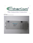
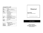
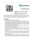
ETP1010 Fault Tolerant Transceiver EtherCom Corporation 1409 Fulton Place, Fremont, CA 94539, USA Tel. (510) 440 0242 Fax. (510) 659 8296 [email protected] USER’S MANUAL ETP 1010 ETP 1010 EtherCom Corporation Limited Warranty Terms: Federal Communications Commission Radio Frequency Interference Statement EtherCom Corporation warrants to the original consumer/purchaser that these products, and all components thereof will be free of defects in workmanship and/or materials, EtherCom Corporation will, at its discretion, repair or replace the defective products or components at no additional cost as set forth herein. Repaired or replacement products will be furnished on an exchange basis and will either be reconditioned or new at the discretion of EtherCom Corporation. All defective items replaced hereunder become the property of EtherCom Corporation. Buyer's sole remedy for breach of any warranty shall be limited, to our sole discretion, to the repair, replacement or refund of the purchase of any products that are returned, and are found to be defective. Buyer assumes all risk and liability for results obtained by use of the products hereunder, whether used singly or in combination with other products. The express warranties set forth herein are made in lieu of all other warranties, express or implied (either in fact or by operation of law). We expressly disclaim all implied warranties of merchantability or fitness for any particular purpose or use. Our support advice shall not create additional warranty or other obligations. This warranty will not be effective if, in the opinion of EtherCom Corporation the product has been damaged by misuse, misapplication, or as a result of service or modification other than by EtherCom Corporation. The limited warranty does not include service to repair damage to products resulting from accident, disaster, misuse, neglect or modification of the product. The term disaster includes such events as lightning strike, flooding, earthquake and fire. During this warranty period EtherCom Corporation will repair or at its option replace components in the products that prove to be defective at no charge other than shipping and handling, provided that the product is returned pre-paid to EtherCom Corporation. Repairs or replacement under this warranty may be carried out by returning the defective unit(s) to EtherCom Corporation. However this may only be done after receiving authorization from EtherCom Corporation. and the issuance of a Return Material Authorization (RMA) number, with shipping charges prepaid, in the original shipping container or like container, and with proof of date of purchase included with the returned product(s). The RMA number issued MUST be marked clearly and visibly on the outside of the shipping container. Any material returned without such RMA markings shall be rejected and returned to sender unopened. There shall be no warranty for either parts or labor after the expiration date of Five years from the original date of purchase. EtherCom Corporation reserves the right to charge for handling and inspecting any product returned for warranty repair that is determined not to be faulty. Products found to be defective in accordance with the above criteria will be returned to the consumer after repair or replacement has been completed and by the carrier and method of deliver chosen by EtherCom Corporation. If the customer desires another specific form of conveyance, or if no problem is found in testing, then the customer shall bear the cost of the return shipment. This equipment generates, uses and can radiate energy and if not installed and used properly, that is in accordance with manufacturer’s instructions, may cause interference to radio communication. It has been tested and found to comply with the comply with the limits for a class A computing device in accordance with the specifications in Subpart J of Part 15 of FCC rules, which are designed to provide reasonable protection against such interference when operated in a commercial environment. Operation of this equipment in a residential area is likely to cause interference, in which case the user at his own expense will be required to implement whatever measures may be required to correct the interference. EtherCom Corporation MAKES NO EXPRESS OR IMPLIED WARRANTIES INCLUDING, BUT NOT LIMITED TO, ANY IMPLIED WARRANTY OF MERCHANTABILITY OR FITNESS FOR A PARTICULAR PURPOSE, EXCEPT AS EXPRESSLY SET FORTH IN THIS WARRANTY. IN NO EVENT SHALL EtherCom Corporation BE LIABLE FOR INCIDENTAL OR CONSEQUENTIAL DAMAGES, COST, OR EXPENSES ARISING OUT OF OR IN CONNECTION WITH THE USE OF PERFORMANCE OF THE PRODUCT DELIVERED HERE UNDER. Copyright Notice Copyright © 1997 by EtherCom Corporation Contents are subject to revision without prior notice. All rights reserved. No part of this manual, or any associated artwork, product design or design concept, may be copied, reproduced or stored, in whole or in part, in any form or by any means mechanical, electronic, optical, photocopying or otherwise, including translation to an other language or format , without the written consent of EtherCom Corporation. Trademarks is the registered trademark of EtherCom Corporation CE Mark Declaration of Conformance This is to certify that this product complies with and conforms to the following specifications: EN 50082-1 (1992), EN 55022 (1995) and EN 60 950 following the provisions of 89/336/EEC & 73/23/ECC Directives. FCC Compliance Statement ETP 1010 ETP 1010 Table of Contents Introduction General Description Key Features Inspecting the Package Installation UTP Crossover Switch Configuration LED Summary Technical Specifications Ordering Information Warranty Note: In this drawing and in drawing on Figure 2 the 2.5/10 switch is set for 2.5 seconds and the reduced squelch is on. ETP1010 is shipped with all switches in off position. Illustrations Choice of ETP1010-TH or ETP1010-TT Features of the ETP1010 A/B, SQE and 2.5/10 Switches Reduced Squelch and Link Switches LEDs for Ports A & B ETP1010 Detail Page 1 Page 1 Page 2 Page 2 Page 3 Page 3 Page 3 Page 4 Page 5 Page 5 Page 7 Page 1 Page 2 Page 3 Page 4 Page 4 Page 6 ETP 1010 ETP 1010 Technical Specifications INTRODUCTION General Description The ETP1010 is a 10 Mbps transceiver built to IEEE 802.3 standards to ensure interoperability with other devices from other manufactures. It has one AUI and two RJ45 connectors, this lets you connect two cables to the unit creating a redundant data path with the second cable. These two cables can be placed through different geographical paths, ensuring data transfer protection should one cable be faulty, cut, damaged or pulled. The two cables can run from one ETP1010 to an other ETP1010 or from an ETP1010 to any two ports of a standard 10 Mbps Ethernet hub, see figure 1. Network Standards Ethernet IEEE 802.3 Speed 10 Mbits/Sec. Power Supply Through the AUI Port LEDs Total 14, 1 for power, 1 for collision, 1 for transmit, 1 for collision, 2 for Receive, 2 for polarity, 2 for Link, 2 for jabber & 2 for enable. Switches Total 7, 2 MDI/MDIX cross over for Ports A & B, 1 for port A or B select, 1 for SQE (heartbeat) enable, 1 2.5 or 10 second select, 2 for reduced squelch & 2 for link. Weight 13 oz. Dimensions 6.9” (175mm) x 2.8” (71mm) x 0.8” (20mm) Environmental Operating Temperature Storage Temperature Relative Humidity condensing) Connectors Two Fully Shielded RJ45 connectors, 1 AUI Connector Cabling UTP Category 3, 4 or 5, maximum cable distance 100 meters, AUI to 50 meters. Regulatory Approvals EMI FCC Class A, CE Warranty 5 years MTBF >300,000 hours 32 to 122F (0 to 50 C) -4 to 140F (-20 to 60 C) 5% to 90% (non- Figure 1. The user can select to make either A or B the primary RJ45 port, by use of the A/B select switch. The ETP1010 will only pass data on the primary port, or on the active port in the case of a cable failure. When a port is not passing data during a ‘quiet period’, the transceiver will begin hunting between ports A and B. This hunting is user selectable intervals of 2.5 or 10 seconds. The transceiver will automatically return to the primary port when it senses that this port is passing valid data. Ordering Part Number: ETP1010 ETP 1010 ETP 1010 LEDs: Summary The ETP1010 has 14 LEDs. There is one LED per transceiver for each of the following: SQE, Indicates SQE switch is on. Should be off during normal operation. TXD, Indicates device is transmitting, should be on during normal operation. COL, Indicates presence of collisions. Normally off during “clear” transmission periods. Will clear when collisions stop. PWR, Indicates transceiver is properly receiving power from the network device to which it is connected through AUI port. Normally on. Key Features Both RJ45 Ports A & B have their own set of five LEDs for each of the following: Figure 2 Figure 5. REC Indicates that the port is receiving. Only one of the two ports should have the receive LED on during reception; the other should be off. LINK Indicates that a proper 10BaseT link has been established at the port. The active port’s Link LED should be the only one on during normal operation. If both LEDs are off, the transceiver is unable to establish a link at either port. The Link LED on the active or enabled port should be on if all connections have been made properly, if the cable is intact, and if the device on the other end of the cable is operational. ENABLE Indicates that the port is the one in use. Only one of the ports should on be in at any given time. During “hunt” periods both LEDs could appear to be on due to the rapid switching occurring as the transceiver searches for valid data. POLIRITY Indicates that the connection being made has the wrong polarity. Needs rewiring or use of crossover switch. Should normally be off. 1 2 3 4 5 6 7 AB, SQE & 2.5/10 Switches AUI Connector SQE LED TXD LED COL LED PWR LED Port B LEDs 8 9 10 11 12 13 Port B Cross-over switch Port B RJ45 Connector Port A RJ45 Connector Port A Cross-over switch Port A LEDs Link & Reduced Squelch Switches Inspection of Package: This package should contain the ETP1010, this manual. Examine the shipping container for obvious damage you believe occurred during shipment or delivery. ETP 1010 ETP 1010 Installation Locating ETP1010 transceivers It is generally more convenient to run an AUI cable from the work-station or network device to the ETP1010 but not necessary, as the AUI connector can plug directly into the device. The two RJ45 cables can be up to 100 meters (328 ft.) in length. Adherence to Ethernet specifications for aggregate twisted pair length should be followed if the AUI cable is more than a few feet. EtherCom’s EMC02 RJ45 to Fiber media converters may be utilized to extend these segments to 2 kilometers. When running cables from an ETP1010 to a second ETP1010 it makes no difference if port A on the first transceiver is connected to port A or port B on the second ETP1010. The ETP1010 is fully compatible with Ethernet V2.0/IEEE 802.3 transceiver specifications for CSMA/CD 10 Mbps operation. makes B the primary port Switch 2, marked SQE, Enables SQE testing. Should be in the off (down) position for operation (normal position upon receipt from factory). Switch 3, marked 2.5-10, Sets timing intervals to either 2.5 or 10 second as the “quiet period” prior to ‘hunting’ to the alternate port, and as “valid carrier period” prior to stopping switching search for data. This switch establishes the delays for both ports as well as for both the quiet and the valid carrier periods. On (up) is for 2.5 & Off (down) for 10 seconds. Note: Switch 4, (unmarked) is disconnected. The second set of 4 switches, located on the right side front (closer to the RJ45 connectors) are: Power is provided through the AUI interface. UTP Crossover Capability: To provide maximum installation flexibility, there is a switch located next to each RJ45 connector. This is a UTP crossover switch that eliminates the need for a specially configured UTP crossover cable. It allows a repeater or a non-repeater device to be attached to the UTP segment side. This switch should be toggled in both directions until you can see that the LINK LED (located next to the A or B) is illuminated. Manual Switches All the switches for the ETP1010 are on the outside of the unit. This makes it unnecessary to take the unit apart and reconfigure jumpers for any changes. There are two sets of miniature slide switches on the front of the unit. Each set consists of four separate switches. The first set, on the left (closer to the AUI connector) only utilizes switches 1, 2 & 3. (switch number 4 is non functional): Switch 1, marked A/B, Selects either port A or port B as primary port. Off (the down position) makes A the primary port & on (the up position) Figure 3 Reduced squelch There are 2 Reduced Squelch switches: one for each RJ45 port (switches 1 and 3). The switch should be normally off for up to 100m meters of unshielded twisted pair to the port. Turn on for shielded twisted pair or for obtaining distance greater than 100 meter transmission range for unshielded twisted pair. This latter condition occurs when the network is “out of spec” (for max. wiring distances); network integrity is at risk when greater than 100 meter unshielded twisted pair segment lengths are used, although the ETP1010 will typically accommodate distances up to 150 meters of unshielded twisted pair if the Reduced Squelch is on. This out of spec condition is not recommended. Link, There is a link switch for each port (switches 2 and 4). Turn on for testing purposes only, during which the automatic searching for link integrity is disabled. Figure 4 Turn off for normal operation to enable automatic switching. There are two-position cross-over switches on the side next to each RJ45 port. These are the Normal or Crossover wiring polarity switches for each port and are labeled with wiring symbols on the top surface. Normal/Crossover The Crossover position enables use with reversed polarity wiring. The Normal position is for standard wiring pin-outs. Refer to the Users Manual for pin-out descriptions.