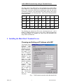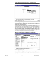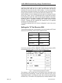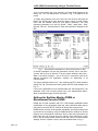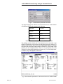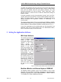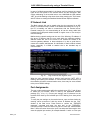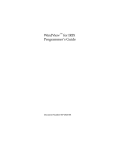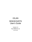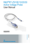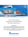
1
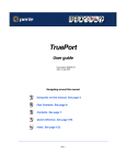
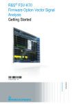
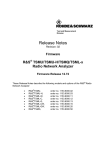
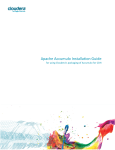
Products: EFA with EFA Scan, DVRM and DVMD with Realtime Monitor or Stream Explorer DVMD-B1
LAN / WAN Connection
Of Instruments with Serial Interface
By Using a Terminal Server
Remote control of test and measurement equipment with a serial interface is limited to PC’s located in
close proximity determined by the length of a typical serial cable connection (several feet). Usage of a
terminal server allows connecting through LAN or WAN networks thus controlling the instrument from
further away even around the globe. The terminal server interfaces between TCP/IP protocol and the
RS232 line.
This application describes set-up of a popular terminal server from Black Box® Corporation to remotely
and conveniently control the instruments EFA with EFA Scan software and DVRM or DVMD with Realtime
Monitor / Stream Explorer software through a LAN or WAN network.
Subject to change – Alexander K.G Wörner 06.03 – 7BM41_0E
LAN / WAN Connection by using a Terminal Server
Contents
1 Overview ................................................................................................. 2
2 Hard- and Software Requirements ......................................................... 2
Hardware Requirements.................................................................... 2
Software Requirements ..................................................................... 3
3 Connecting the Computer and the Instrument(s) ................................... 3
4 Installing the Black Box® Terminal Server ............................................. 4
Choosing and Setting an IP Address with ARP................................. 4
Entering the Terminal Server’s Set-Up Protocol................................ 5
Set-up of the Server’s Network Parameters ...................................... 6
Settings for TV Test Receiver EFA.................................................... 7
Settings for Realtime Monitor DVRM or Measurement Decoder DVMD
........................................................................................................... 8
5 Setting the Application Software ........................................................... 10
EFA Scan Software.......................................................................... 10
Realtime Monitor and Stream Explorer DVMD-B1 .......................... 10
6 Troubleshooting .................................................................................... 11
IP Network Link................................................................................ 12
Port Assignments............................................................................. 12
RS232 Parameters .......................................................................... 13
7 Literature ............................................................................................... 13
8 Ordering information ............................................................................. 13
1 Overview
Remote control capabilities through TCP/IP via an Ethernet interfaces are
these days usually implemented in every test and measurement device due
to the widespread presence of this kind of networking technology. It
provides for easy access and routing of signals through any local site and
even around the world. Earlier serial interfaces of RS232 type have been the
default and are still in legacy use. To utilize this new technology even in
cases when only an RS232 interface is present a terminal server can be
used for interfacing. It converts the commands from TCP/IP protocol
addressed to a dedicated port at the given Ethernet address into RS232
signals on a serial interface and back.
2 Hard- and Software Requirements
Hardware Requirements
The application note discusses the required settings for a terminal server
from Black Box® Corporation using instruments of type DVRM, DVMD and
EFA. The model that is described in the application note is the 4 port
desktop version #41874. Other models, like the 2 port desktop #41874 or
rack mount versions (#40871 for 8 ports and #40870 for 16 ports) are
working in the same manner.
The 8-port (#37688) and 16-port (#37687) desktop versions will be identical
regarding software set-up, however they require different cable connections,
as they have 25 pin DB25 connector plugs for the serial interfaces (DB9 to
DB25 null modem cables).
7BM41_0E
2
Rohde & Schwarz
LAN / WAN Connection by using a Terminal Server
Terminal servers from different manufacturers can be used, but will require
different steps for set-up. Please refer to the manufacturer’s manual for
detailed instructions in any case. All notes regarding set-up of the
application software packages (EFA Scan, Realtime Monitor and Stream
Explorer) and the instruments in section 5 are usually valid no matter which
terminal server is used.
Software Requirements
The application software used for remote control through a terminal server
needs to have a method of sending and receiving the instruments
commands directly to and from an Ethernet port with a given TCP/IP
address and a port number instead of the local RS232 port. All three
software packages discussed in this application note (Realtime Monitor,
Stream Explorer DVMD-B1 and EFA Scan) have that basic capability.
If the application software does not offer this direct addressing capability (for
example Pcx2disc.exe), separate server software is needed to emulate a
local COM port by running as a background task. In that case the
application software will see the remote serial interfaces identical to local
interfaces, one of which can be chosen in the set-up as the port of choice.
The server software then converts all remote commands to and from the
application software into the TCP/IP channel and communicates with the
terminal server at the other end. This application note does not describe the
latter type of communication through a software server, but rather the direct
addressing of the terminal server’s Ethernet (TCP/IP) address by the
application software.
As far as operating systems and versions are concerned, the capabilities of
the application software packages have to be observed. At the time of
writing both Realtime Monitor and Stream Explorer DVMD-B1 will operate
on any PC with Pentium 100 MHz processor and either one of the following
operating systems: Microsoft® Windows NT® 4.0, Windows 95, 98 and
2000. EFA Scan will work under all these mentioned operating systems as
well as with Windows ME and XE. There is no limitation known for the usage
of the terminal server regarding processors and operating systems.
3 Connecting the Computer and the Instrument(s)
LAN / WAN
Internet
Terminal
Server
RS232
Connections
EFA
Fig. 1
DVRM
Connection diagram between computer and instruments
The discussed terminal servers from Black Box® have RJ45 plugs for the
serial interfaces, requiring RJ45 CAT5 patch cables to be used with a DB9
adapter. All of these items can conveniently be ordered from the same
supplier. Order numbers are listed in section 8 at the end of the document.
7BM41_0E
3
Rohde & Schwarz
LAN / WAN Connection by using a Terminal Server
The other ends of the cables have to be terminated by a female DB9 to
RJ45 adapter kit in order to plug it into the male DB9 connectors at the rear
panel of the instruments. Black Box® manufactures those kits that allow
customized connection of the individual wires easily through color-coding.
The connections from the following Table 1 have proven working with EFA,
DVRM and DVMD:
RJ45
1
2
3
4
5
6
7
8
Signal
DCD
RTS
DSR
TXD
RXD
GND
CTS
DTR
DB9
NC
8
4
2
3
5
7
6
Signal
NC
CTS
DTR
RXD
TXD
GND
RTS
DSR
Color
Blue
Orange
Black
Red
Green
Yellow
Brown
White
Table 1: Connection diagram between computer and the instruments
The following text assumes an EFA to be connected with port 1 and a
DVRM or DVMD connected to port 2 of the server. Different assignments
are always possible. For example one server could be connected to an
array of EFA or DVRM units.
4 Installing the Black Box® Terminal Server
Choosing and Setting an IP Address with ARP
The terminal server
comes with a fixed
hardware
MAC
address in the form
00:80:D4:04:42:A3,
which is printed at
the bottom of the
server. Temporarily
an
IP
network
address has to be
assigned to that
network
address
using the “arp”
(address resolution
protocol) command
in a DOS or
Command Prompt
window.
The
chosen IP address
has to match the
range
of
IP
addresses the PC
can communicate
within its current
sub group.
Fig. 2
7BM41_0E
4
TCP/IP network properties within Windows® 2000
Rohde & Schwarz
LAN / WAN Connection by using a Terminal Server
This range of addresses can be determined by the PC’s own IP address and
the network sub-mask setting, both of which are found in the Control Panel /
Network settings under “Properties” for the “Internet Protocol (TCP/IP)
components. Fig. 2 shows sample settings of a PC under Microsoft
Windows 2000. Only the last 8 bits may vary for the IP address of the
server, since the first six bytes are all set, indicated by the three 255’s. A
potential IP address for the server may only be 192.168.177.x with x any
number between 3 and 255 (1 is gateway, 2 is PC)
This process of assigning an IP address to the physical hardware Ethernet
address and further directions are also described in the terminal server’s
owner manual section 2.3 (Communicating via ARP) and later with great
detail.
Entering the Terminal Server’s Set-Up Protocol
After that a telnet session can be started for communication with the
terminal server. Enter the command “telnet” into the “Run” window that is
found in the “Start” menu. Within the Telnet window an “open rrr.sss.ttt.uuu”
command will initiate communication with the terminal server, where the
parameter of this command is the IP address previously assigned to the
server’s hardware address. The full command with the sample settings from
Fig. 1 is “open 192.168.177.2”. The server will then respond with a
“TSERVER password” prompt indicating its readiness to receive input.
Fig. 3
Entering the terminal server’s command line mode
The default password is an empty string, so pressing the Return key will let
the user proceed. The server will then respond with a “TSERVER>” prompt
waiting for command input. At this time it is still in a command line mode,
sending and receiving one line of characters or parameters at a time. This
initiating dialog is displayed in the following Fig. 3.
The terminal server will then enter its form based operating mode, where all
information is presented in full text screen mode for easy editing. The first
menu to appear will be the “Connections Menu”. To move on to the
“Administration Menu” for modification of the parameters press the Return
key, keep the cursor bar in the “Admin mode” and press the Return key
again. This dialog is shown in Fig. 4.
7BM41_0E
5
Rohde & Schwarz
LAN / WAN Connection by using a Terminal Server
Fig. 4
Entering the terminal server’s administration mode
A list of menu items (i.e. gateway, host, line) to choose from will appear in a
window titled “Administration Menu”.
In order to make any changes to the configuration a password has to be
entered. Move the cursor with the down key to the “password” parameter
and press the Return key. Enter the default password “iolan” into the empty
field and press Return again. The original list will reappear with four more
items in it (“access”, “change”, “kill” and “reboot”). Move the cursor bar down
in the list to the parameter “server” and press the Return key again. The
menu “Server Configuration” as depicted in Fig. 5 will appear.
Set-up of the Server’s Network Parameters
Fig. 5
Modifying the terminal server’s network configuration
Here a permanent assignment of the IP address that was chosen at the
beginning of this section should be set. The subnet mask must match the
7BM41_0E
6
Rohde & Schwarz
LAN / WAN Connection by using a Terminal Server
computer’s subnet mask from Fig. 2. Enter the values in the relevant field
after moving the curser bar up or down. Use the Return key twice to
terminate the entry and save the edited settings. To cancel any changes
while editing a field press the Return key and then choose “Quit & Exit” from
the pop-up menu with the cursor down key followed by the Return key.
After modification of the IP address the server has to be rebooted. Choose
the list item “reboot” from the “Administration Menu” and press the Return
key followed by the space bar. After the telnet program displays “Connection
to host lost” start all over again by entering “open rrr.sss.ttt.uuu” and follow
directions given in sub-section “Entering the Terminal Server’s Set-up
Protocol”. Following that the individual port settings have to be adjusted
according to the instruments used.
The Ethernet address field in the “Server Configuration” menu must not be
modified.
Settings for TV Test Receiver EFA
These sample settings are recommended for the serial interface of EFA and
assumed in the following, others may be possible as well:
Baud rate
19200
Data bits
8
Parity
Even
Stop Bit
1
Hand shake
Hardware
Table 2: RS232 interface parameters for EFA
Use the key sequence SETUP / REMOTE / RS232 at the front panel of EFA
to set the parameters locally. The GUI menu is shown in Fig. 6.
Fig. 6
Serial interface parameters on EFA
The settings on the relevant port of the terminal server connected to the
EFA have to be set accordingly. To enter the menu use the item “port” in the
“Administration Menu” by moving the cursor bar to that item and pressing
the Return key. The number of the physical port (for example between 1 and
7BM41_0E
7
Rohde & Schwarz
LAN / WAN Connection by using a Terminal Server
4 on a 4 port server) has to be entered in an empty field followed by the
Return key. The “Port Setup Menu” as shown in Fig. 7 will appear on the
screen.
To modify any parameter move the cursor bar over the item and press the
Return key. A little pop-up menu gives the choice “values” to enter another
menu with the allowed values for that specific parameter. The most
important parameters to be set are “Speed”, “Parity”, (data) “Bits”, “Stop”
(bit) and “Flow ctrl”, which all have to match the instrument’s settings on the
EFA.
Fig. 7
Serial interface parameters on the terminal server for EFA
Of further importance are also the parameters “Access” and “Local Port”.
“Access” has to be set to “Remote”. The port number entered in this menu –
9000 in the shown example – has to be used in conjunction with the IP
address throughout the application software for addressing of all
communication.
The sample settings shown in Fig. 7 are matching the EFA’s serial interface
setting from Fig. 6 as well as the setting within the EFA Scan software from
Fig. 10.
If none of the parameters can be modified within the “Port Setup Menu”, the
password “iolan” has not been entered yet in the “Administration Menu”,
which is described on page 5 of this document.
Settings for Realtime Monitor DVRM or
Measurement Decoder DVMD
DVMD with its local operation and LCD / OSD display capabilities allows
modifications of the parameters baud rate, parity and hand shake (pace).
Using the menu items SETUP / RS232 will access the required menu.
DVRM doesn’t have any local operation capabilities. So whichever baud rate
is used has to be preset by using the Realtime Monitor software or Stream
Explorer and a local RS232 connection. None of the other parameters are
fixed within the unit. Consult the user’s manual of the instrument to learn
how to set-up RS232 based remote control and choose “Communications
Settings” from the “Options” menu to open the window shown in Fig. 8.
7BM41_0E
8
Rohde & Schwarz
LAN / WAN Connection by using a Terminal Server
Fig. 8
Serial interface parameters on DVRM
The sample settings from Table 3 are recommended for the serial interface
of DVRM and DVMD and assumed in the following.
Baud rate
115 200
Data bits
8
Parity
None
Stop Bit
1
Hand shake
Hardware
Table 3: RS232 interface parameters for DVRM and DVMD
The settings on the relevant port of the terminal server connected to the
DVRM or DVMD have to be matching the individual instrument’s settings. To
enter the menu use the item “port” in the “Administration Menu” by moving
the cursor bar to that item and pressing the Return key. The number of the
physical port (for example between 1 and 4 on a 4 port server) has to be
entered in an empty field followed by the Return key. The “Port Setup Menu”
as shown in Fig. 9 will appear on the screen.
Fig. 9 Serial interface parameters on the terminal server for DVRM / DVMD
7BM41_0E
9
Rohde & Schwarz
LAN / WAN Connection by using a Terminal Server
To modify any parameter move the cursor bar over the item and press the
Return key. A little pop-up menu gives the choice “values” to enter another
menu with the allowed values for that specific parameter. The most
important parameters to be set are “Speed”, “Parity”, (data) “Bits”, “Stop”
(bit) and “Flow ctrl”, which all have to match the instrument’s settings of
DVRM or DVMD.
Of further importance are also the parameters “Access” and “Local Port”.
“Access” has to be set to “Remote”. The port number entered in this menu –
9100 in the shown example – has to be used in conjunction with the IP
address throughout the application software for addressing of all
communication.
The sample settings shown in Fig. 9 are matching the DVRM’s or DVMD’s
serial interface setting from Fig. 8 as well as the calling command within the
Realtime Monitor or Stream Explorer DVMD-B1 software shown in Fig. 11.
If none of the parameters can be modified within the “Port Setup Menu”, the
password “iolan” has not been entered yet in the “Administration Menu”,
which is described on page 5 of this document.
5 Setting the Application Software
EFA Scan Software
This software provides easy
access to facilitate remote
control via LAN / WAN
connections. Simply click on
“Options” in the “Tools”
menu,
choose
route
“TCP/IP” and enter the IP
address of the terminal
server as set earlier (Fig. 5)
and the port number set up
for EFA (Fig. 7). The “Test”
button allows for a quick
communication
test.
If
everything was set properly
and the EFA is connected to
the terminal server at the
port, that was assigned the
specified port number, the
unit’s firmware will send a
string back including the
serial and model numbers
as well as the firmware
version.
Fig. 10 TCP/IP communication menu with EFA Scan
Realtime Monitor and Stream Explorer DVMD-B1
The Realtime Monitor software comes with all DVRMs or can be freely
download from the Rohde & Schwarz homepage at http://www.rohdeschwarz.com (PRODUCTS / TEST & MEASUREMENT / AUDIO, VIDEO &
TV / PRODUCTS / DVRM / DOWNLOAD button).
7BM41_0E
10
Rohde & Schwarz
LAN / WAN Connection by using a Terminal Server
Stream Explorer (with the product name “DVMD-B1”) is a charged option to
DVRM or DVMD that includes all the remote features of Realtime Monitor.
Furthermore it features additional in-depth measurement capabilities like
PCR jitter and table repetition rates.
To use either of the two
application
software
packages via any LAN /
WAN connection, the
target information within
the desktop or start
menu
shortcut
of
windows has to be
modified. Click with the
right mouse key on the
desktop icon or start
menu item within the
Windows
Explorer
window and choose
“Properties” from the
pop-up menu. A string
has to be appended to
the
existing
calling
command, which must
include the IP address
and the port number
assigned to the physical
port of the terminal
server.
Fig. 11 Shortcut Properties for TCP/IP communication of
Stream Explorer or Realtime Monitor
The string to be added to the existing target for the program’s exe file is:
/IP:rrr.sss.ttt.uuu /PORT:vvvv
Within this string “rrr.sss.ttt.uuu” has to be replaced by the IP address
previously assigned to the terminal server at the beginning of section 4 (Fig.
5) and “vvvv” is to be replaced by the port number assigned to the physical
port to which the DVRM or DVMD is connected (Fig.9). Fig. 11 shows a
working example for the software Stream Explorer and with the previously
used sample values.
6 Troubleshooting
The EFA Scan software provides an easy way to test proper communication
with the device over TCP/IP. In the Options / Remote Control set-up menu
the “Test” button will send a command and read back a test string from the
instrument, which is displayed within the same window (Fig. 10). If
communication fails, then the string “Failed” would be entered within that
field instead.
Realtime Monitor and Stream Explorer will always open their user interface
regardless of a success in communicating with DVRM or DVMD. If
communication fails, either software will display “RS232 Error” on a red
background at the right end of the status bar, which is located at the bottom
of the user interface.
7BM41_0E
11
Rohde & Schwarz
LAN / WAN Connection by using a Terminal Server
In case of a failed communication it is always useful to observe the control
lights at the front panels of the terminal server and the instrument. With
correct addressing of the terminal server over LAN/WAN the LED marked
“NET” should be flashing a few times when either pressing the “Test” button
with EFA Scan or starting the Realtime Monitor/Stream Explorer software.
IP Network Link
The Basic network link can be tested using the ping command in an MSDOS or “Command Prompt” window. If the results are looking like in Fig. 12,
the PC is basically not able to communicate with the terminal server.
Potential reasons for not communicating at all can be wrong cable links
(crossed-over RJ45 patch cables instead of regular ones or vice versa) or
incorrect settings.
Malfunctioning network settings can be one of the following: IP address of
the server is different than the one used within the software package,
address masks are set for the server to be outside the subnet or an
incorrect gateway address. In these situations it is also a good idea to
contact the network administrator for clarification of basic network related
issues, especially if a WAN to another site is the intended way of
communication.
Fig. 12
Ping command with negative result
When the ping command gives a positive result and the “NET” LED is
flashing upon starting the software or communication with the device, but
the software still shows communication errors, there may be errors related
to the port or RS232 settings.
Port Assignments
The port number assignments within the terminal server (Fig. 7 and 9) have
to match the port number, which is used by the application software
package (Fig. 10 or 11). Correct port settings can be observed on the
terminal server itself by the individual port “LED” flashing for a short period
of time.
To verify the port settings on the terminal server, open a telnet window by
entering “telnet rrr.sss.ttt.uuu” with the correct IP address into the “Run”
window of the Start menu. Press Return to confirm the “TSERVER
password” command and enter “set term ansi” at the “TSERVER>”
command prompt. Press the Return key twice to enter the “Administration
Menu”. Move the cursor down to the “port” line and press Return again. Now
enter the physical port number (for example between 1 and 4 on a four port
7BM41_0E
12
Rohde & Schwarz
LAN / WAN Connection by using a Terminal Server
server) in order to enter the “Port Setup Menu” for this individual RS232
port. The menu displays the actual settings including the port number to be
used during IP addressing as well as the RS232 characteristics.
To make any changes the password “iolan” has to be entered in the
“Password” command in the previous “Administration Menu” display.
RS232 Parameters
The serial interface parameters like baud rate, number of bits, number of
stop bits, parity and hand shake of the instrument (Fig. 6 and 8) have to
match the terminal server’s settings for the relevant port (Fig. 7 and 9). The
settings of EFA and DVMD can easily be modified in their respective user
interface menus on the front display. To view or modify the RS232
parameters of a DVRM the Realtime Monitor or Stream Explorer software
has to be used through a local RS232 port on a PC or notebook, as the
DVRM has no manual user interface.
When checking the port settings on the terminal server, it is of utmost
importance to check the field “Access” to be set to “Remote”, as this specific
entry is different from the manufacturer’s default. Other important
parameters are “Mode” (should be “raw”) and “RLogin/Telnet” set to
“Telnet”.
Non-matching RS232 settings might be observed on an EFA also by
watching it change into remote status but not returning into local mode.
Once the command sequence that EFA Scan is processing has been
finished, the LED marked “REM” indicating the remote status of the
instrument is supposed to darken again. If it stays active, the RS232
parameters usually are not correct.
7 Literature
EFA Operating Manual
2068.0950.12-14
DVMD Operating Manual
2069.0348.12-07
DVRM Operating Manual
2069.0231.12-02
Black Box® Corporation, Terminal Server – User and Administration Guide
8 Ordering information
Rohde & Schwarz products and options
EFA
TV Test Receiver
EFA-K1
EFA Scan software
DVRM
MPEG2 Real Time Monitor incl. software RTmon
DVMD
MPEG2 Measurement Decoder
DVMD-B1
Stream Explorer™ software
2067.3004.xx
2067.9202.02
2068.8580.02
2068.8597.02
2068.9406.02
Black Box® Corporation products and options
41872
2 Port Desktop Terminal Server
41874
4 Port Desktop Terminal Server
40871
8 Port Rack Mount Terminal Server
40870
16 Port Rack Mount Terminal Server
37688
8 Port Desktop Terminal Server (requires different cabling)
37687
16 Port Desktop Terminal Server (requires different cabling)
FA756
Female DB9 - RJ45 Thumbscrew Wire Adapter Kit
EVNSLcc-0ddd CAT5 Patch Cable in different colors and lengths:
cc: 21 blue / 22 green / 23 red / 24 yellow / 25 beige / 26 pink / 27 black
ddd: 001 / 003 / 006 / 010 / 015 / 020 / 025 / 030 / 050 / 100 (length in feet)
7BM41_0E
13
Rohde & Schwarz
LAN / WAN Connection by using a Terminal Server
.
.
ROHDE & SCHWARZ Inc. 8661 Robert Fulton Drive, Suite A Columbia, Maryland, USA-21046
.
.
Telephone +1 410 910 7800 Fax +1 410 910 7801 Internet: http://www.rohde-schwarz.com
This application note and the supplied programs may only be used subject to the conditions of use set forth in the download
area of the Rohde & Schwarz website.
7BM41_0E
14
Rohde & Schwarz