1
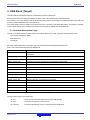
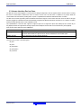
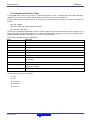
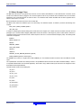
32 SH7269 Group Renesas Starter Kit + USB Function Sample Code User’s Manual RENESAS MCU SH Family / SH2A Series All information contained in these materials, including products and product specifications, represents information on the product at the time of publication and is subject to change by Renesas Electronics Corporation without notice. Please review the latest information published by Renesas Electronics Corporation through various means, including the Renesas Electronics Corporation website (http://www.renesas.com). Rev.1.00 May 2012 Notice 1. 2. 3. 4. 5. 6. 7. All information included in this document is current as of the date this document is issued. Such information, however, is subject to change without any prior notice. Before purchasing or using any Renesas Electronics products listed herein, please confirm the latest product information with a Renesas Electronics sales office. Also, please pay regular and careful attention to additional and different information to be disclosed by Renesas Electronics such as that disclosed through our website. Renesas Electronics does not assume any liability for infringement of patents, copyrights, or other intellectual property rights of third parties by or arising from the use of Renesas Electronics products or technical information described in this document. No license, express, implied or otherwise, is granted hereby under any patents, copyrights or other intellectual property rights of Renesas Electronics or others. You should not alter, modify, copy, or otherwise misappropriate any Renesas Electronics product, whether in whole or in part. Descriptions of circuits, software and other related information in this document are provided only to illustrate the operation of semiconductor products and application examples. You are fully responsible for the incorporation of these circuits, software, and information in the design of your equipment. Renesas Electronics assumes no responsibility for any losses incurred by you or third parties arising from the use of these circuits, software, or information. When exporting the products or technology described in this document, you should comply with the applicable export control laws and regulations and follow the procedures required by such laws and regulations. You should not use Renesas Electronics products or the technology described in this document for any purpose relating to military applications or use by the military, including but not limited to the development of weapons of mass destruction. Renesas Electronics products and technology may not be used for or incorporated into any products or systems whose manufacture, use, or sale is prohibited under any applicable domestic or foreign laws or regulations. Renesas Electronics has used reasonable care in preparing the information included in this document, but Renesas Electronics does not warrant that such information is error free. Renesas Electronics assumes no liability whatsoever for any damages incurred by you resulting from errors in or omissions from the information included herein. Renesas Electronics products are classified according to the following three quality grades: “Standard”, “High Quality”, and “Specific”. The recommended applications for each Renesas Electronics product depends on the product’s quality grade, as indicated below. You must check the quality grade of each Renesas Electronics product before using it in a particular application. You may not use any Renesas Electronics product for any application categorized as “Specific” without the prior written consent of Renesas Electronics. Further, you may not use any Renesas Electronics product for any application for which it is not intended without the prior written consent of Renesas Electronics. Renesas Electronics shall not be in any way liable for any damages or losses incurred by you or third parties arising from the use of any Renesas Electronics product for an application categorized as “Specific” or for which the product is not intended where you have failed to obtain the prior written consent of Renesas Electronics. The quality grade of each Renesas Electronics product is “Standard” unless otherwise expressly specified in a Renesas Electronics data sheets or data books, etc. “Standard”: Computers; office equipment; communications equipment; test and measurement equipment; audio and visual equipment; home electronic appliances; machine tools; personal electronic equipment; and industrial robots. “High Quality”: Transportation equipment (automobiles, trains, ships, etc.); traffic control systems; anti-disaster systems; anticrime systems; safety equipment; and medical equipment not specifically designed for life support. “Specific”: Aircraft; aerospace equipment; submersible repeaters; nuclear reactor control systems; medical equipment or systems for life support (e.g. artificial life support devices or systems), surgical implantations, or healthcare intervention (e.g. excision, etc.), and any other applications or purposes that pose a direct threat to human life. 8. You should use the Renesas Electronics products described in this document within the range specified by Renesas Electronics, especially with respect to the maximum rating, operating supply voltage range, movement power voltage range, heat radiation characteristics, installation and other product characteristics. Renesas Electronics shall have no liability for malfunctions or damages arising out of the use of Renesas Electronics products beyond such specified ranges. 9. Although Renesas Electronics endeavors to improve the quality and reliability of its products, semiconductor products have specific characteristics such as the occurrence of failure at a certain rate and malfunctions under certain use conditions. Further, Renesas Electronics products are not subject to radiation resistance design. Please be sure to implement safety measures to guard them against the possibility of physical injury, and injury or damage caused by fire in the event of the failure of a Renesas Electronics product, such as safety design for hardware and software including but not limited to redundancy, fire control and malfunction prevention, appropriate treatment for aging degradation or any other appropriate measures. Because the evaluation of microcomputer software alone is very difficult, please evaluate the safety of the final products or system manufactured by you. 10. Please contact a Renesas Electronics sales office for details as to environmental matters such as the environmental compatibility of each Renesas Electronics product. Please use Renesas Electronics products in compliance with all applicable laws and regulations that regulate the inclusion or use of controlled substances, including without limitation, the EU RoHS Directive. Renesas Electronics assumes no liability for damages or losses occurring as a result of your noncompliance with applicable laws and regulations. 11. This document may not be reproduced or duplicated, in any form, in whole or in part, without prior written consent of Renesas Electronics. 12. Please contact a Renesas Electronics sales office if you have any questions regarding the information contained in this document or Renesas Electronics products, or if you have any other inquiries. (Note 1) “Renesas Electronics” as used in this document means Renesas Electronics Corporation and also includes its majorityowned subsidiaries. (Note 2) “Renesas Electronics product(s)” means any product developed or manufactured by or for Renesas Electronics. Disclaimer By using this Renesas Starter Kit (RSK), the user accepts the following terms: The RSK is not guaranteed to be error free, and the entire risk as to the results and performance of the RSK is assumed by the User. The RSK is provided by Renesas on an “as is” basis without warranty of any kind whether express or implied, including but not limited to the implied warranties of satisfactory quality, fitness for a particular purpose, title and non-infringement of intellectual property rights with regard to the RSK. Renesas expressly disclaims all such warranties. Renesas or its affiliates shall in no event be liable for any loss of profit, loss of data, loss of contract, loss of business, damage to reputation or goodwill, any economic loss, any reprogramming or recall costs (whether the foregoing losses are direct or indirect) nor shall Renesas or its affiliates be liable for any other direct or indirect special, incidental or consequential damages arising out of or in relation to the use of this RSK, even if Renesas or its affiliates have been advised of the possibility of such damages. Precautions The following precautions should be observed when operating any RSK product: This Renesas Starter Kit is only intended for use in a laboratory environment under ambient temperature and humidity conditions. A safe separation distance should be used between this and any sensitive equipment. Its use outside the laboratory, classroom, study area or similar such area invalidates conformity with the protection requirements of the Electromagnetic Compatibility Directive and could lead to prosecution. The product generates, uses, and can radiate radio frequency energy and may cause harmful interference to radio communications. However, there is no guarantee that interference will not occur in a particular installation. If this equipment causes harmful interference to radio or television reception, which can be determined by turning the equipment off or on, you are encouraged to try to correct the interference by one or more of the following measures; • ensure attached cables do not lie across the equipment • reorient the receiving antenna • increase the distance between the equipment and the receiver • connect the equipment into an outlet on a circuit different from that which the receiver is connected • power down the equipment when not in use • consult the dealer or an experienced radio/TV technician for help NOTE: It is recommended that wherever possible shielded interface cables are used. The product is potentially susceptible to certain EMC phenomena. To mitigate against them it is recommended that the following measures be undertaken; • The user is advised that mobile phones should not be used within 10m of the product when in use. • The user is advised to take ESD precautions when handling the equipment. The Renesas Starter Kit does not represent an ideal reference design for an end product and does not fulfil the regulatory standards for an end product. R20UT0595EG0100 May 23, 2012 Page iii of vi How to Use This Manual 1. Purpose and Target Readers This manual is designed to provide the user with an understanding of the RSK hardware functionality, and electrical characteristics. It is intended for users designing sample code on the RSK platform, using the many different incorporated peripheral devices. The manual comprises of an overview of the capabilities of the RSK product, but does not intend to be a guide to embedded programming or hardware design. Further details regarding setting up the RSK and development environment can found in the tutorial manual. Particular attention should be paid to the precautionary notes when using the manual. These notes occur within the body of the text, at the end of each section, and in the Usage Notes section. The revision history summarizes the locations of revisions and additions. It does not list all revisions. Refer to the text of the manual for details. The following documents apply to the SH7269 Group. Make sure to refer to the latest versions of these documents. The newest versions of the documents listed may be obtained from the Renesas Electronics Web site. Document Type Description Document Title Document No. User’s Manual Describes the technical details of the RSK hardware. RSK+SH7269 User’s Manual R20UT0592EG Tutorial Manual Provides a guide to setting up RSK environment, running sample code and debugging programs. RSK+SH7269 Tutorial Manual R20UT0593EG Quick Start Guide Provides simple instructions to setup the RSK and run the first sample, on a single A4 sheet. RSK+SH7269 Quick Start Guide R20UT0594EG Schematics Full detail circuit schematics of the RSK. RSK+SH7269 Schematics D010332 Hardware Manual Provides technical microcontroller. RSK+SH7269 Hardware Manual R01UH0048EJ R20UT0595EG0100 May 23, 2012 details of the SH7269 Page iv of vi 2. List of Abbreviations and Acronyms Abbreviation Full Form ADC Analog to Digital Converter CDC HAL Communication Device Class Hardware Abstraction Layer HID LCD Human Interface Device Liquid Crystal Display LED MSC Light Emitting Diode Mass Storage Class RSK USB Renesas Starter Kit Universal Serial Bus R20UT0595EG0100 May 23, 2012 Page v of vi Table of Contents 1. Overview ............................................................................................................................................ 1 2. Development Environment ................................................................................................................ 2 2.1 RSK Configuration .................................................................................................................................................... 2 2.2 Sample Code Configuration ...................................................................................................................................... 2 2.3 Target Sample Code Options ..................................................................................................................................... 2 2.4 Host Application Software......................................................................................................................................... 2 3. USB Stack (Target) ............................................................................................................................ 3 3.1 Hardware Abstraction Layer ...................................................................................................................................... 3 3.2 USBCore ................................................................................................................................................................... 5 3.3 Human Interface Device Class .................................................................................................................................. 7 3.4 Communication Device Class ................................................................................................................................... 8 3.5 Mass Storage Class .................................................................................................................................................... 9 4. Applications ...................................................................................................................................... 10 4.1 Introduction to Applications .................................................................................................................................... 10 4.2 Human Interface Device Application ...................................................................................................................... 10 4.3 Communications Device Class Application ............................................................................................................ 11 4.4 Mass Storage Class Demonstration ......................................................................................................................... 15 4.5 LibUSB .................................................................................................................................................................... 16 5. Additional Information ..................................................................................................................... 18 R20UT0595EG0100 May 23, 2012 Page vi of vi RSK+SH7269 Development Environment 1. Overview The RSK USB sample code provides a basis for a developer to add USB device functionality to a system. It includes sample applications for the three most common USB Device classes *:• Human Interface Device (HID) • Communication Device Class - Abstract Control Model (CDC-ACM) • Mass Storage Class (MSC) In addition to the three defined USB classes a LibUSB sample is included. LibUSB is an open source project with the aim of providing a library that a user application can utilise to access a USB device regardless of operating system. A sample using a Microsoft Windows XP host is provided. The embedded software is available as source written in ANSI C and does not require an operating system. The host applications software is also available as source written for MS Windows using VisualC++. This manual describes the USB sample code. The Quick Start Guide and Tutorial Manual provide details of the software installation and debugging environment. Samples Classes HID Demo CDC Demo MSC Demo HID CDC MSC LibUSB Demo USB Stack USB Core Driver HAL USB Hardware Figure 1 - Embedded SW, including Layers of USB Stack * See specific sections for details. Tested with a USB Host PC running MS Windows XP SP2. HID and LibUSB samples both include a PC Application. R20UT0595EG0100 May 23, 2012 Page 1 of 18 RSK+SH7269 Development Environment 2. Development Environment 2.1 RSK Configuration This board is configured to support USB function modes via software so no hardware configuration is required. 2.2 Sample Code Configuration The Sample code is provided as a project generator with the RSK. To create the sample code project follow the instructions in the RSK Quick Start Guide. When created the sample code will contain the source for both the Target project and a Host project if applicable, including any configuration driver files. 2.3 Target Sample Code Options When developing USB software it is useful to be able to get debug information out at runtime without stopping code from running such as when stepping in a debugger. All modules of the USB Stack software include debug messages that can be utilised in a system that supports printf. The sample applications all support printf and the output is viewable via the serial port of the RSK. To view the serial output the following settings are required: Baud: 57600. Data: 8 Bit. Parity: None. Stop Bits: 2. Flow: None. The level of debug message can be set using the #define DEBUG_LEVEL. This is described in the file usb_common.h in the USBStack directory. Note that a high level of debug messages can significantly slow down the system. 2.4 Host Application Software To build the Microsoft Visual C++ Applications you will need to have the appropriate Windows Software Development Kit (SDK) and the Windows Driver Kit (WDK) installed. These kits provide access to the library functions to access USB devices and are available directly from Microsoft. We have provided the links to the current locations however we cannot guarantee the suitability or accuracy of these links. Both must be installed to be able to build the application, we suggest installing the SDK first. Windows SDK Windows Driver Kit (WDK) R20UT0595EG0100 May 23, 2012 Page 2 of 18 RSK+SH7269 USB Stack 3. USB Stack (Target) The USB software is implemented in the form of a USB stack comprising of three layers. At the top of the stack are the USB Device Classes consisting of HID, CDC and MSC which are all described later. In the middle is a core layer (USBCore) that handles standard device requests. At the bottom is a hardware abstraction layer (HAL) that provides a hardware independent API for the upper layers. This modular design means this software can be still be used even if developing a proprietary USB interface. For example a proprietary module could be implemented by calling functions directly exposed by both the USBHAL API and USBCore API. 3.1 Hardware Abstraction Layer The HAL is a hardware specific layer that provides a non-hardware specific API. The HAL supports the following transfer modes: Control (Setup, Data IN/OUT, Status) Bulk (IN and OUT) Interrupt (IN) Some HAL implementations may not be able to support all these modes but the SH7269 implementation does. Here is a list of the functions that make up the USBHAL API. Name Description USBHAL_Init Initialise the HAL. Register callback functions. If using the USB Core layer then this is done automatically. USBHAL_Config_Get Get the current HAL configuration. USBHAL_Config_Set Set the current HAL configuration. USBHAL_Control_ACK Generate an ACK on the Control IN pipe. (Used following a setup packet) USBHAL_Control_IN Send data on the Control IN pipe. (Used following a setup packet) USBHAL_Control_OUT Receive data on the Control OUT pipe. (Used following a setup packet) USBHAL_Bulk_IN Send data on the Bulk IN pipe. USBHAL_Bulk_OUT Receive data on the Control OUT pipe. USBHAL_Interrupt_IN Send data on the Control IN pipe. USBHAL_Reset Reset this module. (Following an error). USBHAL_Control_Stall Stall the control pipe. (Used following a setup packet) USBHAL_Bulk_IN_Stall Stall the Bulk IN pipe. USBHAL_Bulk_OUT_Stall Stall the Bulk OUT pipe. USBHAL_Interrupt_IN_Stall Stall the Interrupt IN pipe. USBHALInterruptHandler The system must be setup so that this gets called when any USB Interrupt occurs. The HAL module consists of the following files:usb_hal.c - This file provides a hardware independent API to the USB peripheral. usb_hal.h. - This file provides definition for low level driver. usb_common.h - This file provides definition common to upper and lower level USB driver. R20UT0595EG0100 May 23, 2012 Page 3 of 18 RSK+SH7269 USB Stack The following files are used as helper files for HAL module. dataio.c - This file consist of USB FIFO read write functions accessed by HAL module. global.c - This file contains declarations of global variables and common functions. lib7269.c - This file contains USB hardware related functions specific to microcontroller SH7269. libint.c - This file contains USB interrupt handlers specific to SH7269 CPU. R20UT0595EG0100 May 23, 2012 Page 4 of 18 RSK+SH7269 USB Stack 3.2 USBCore The USBCore layer handles standard USB requests common to all USB devices during the enumeration stage. This means that a developer can concentrate on any class or vendor specific implementation. The USBCore requires initialising with the descriptors specific to the device being implemented. It uses the USBHAL, which it initialises, to access the particular HW. The following Standard Requests are handled in USBHAL: • • • • • • • • Get_Status Clear_Feature Set_Feature Get_Descriptor Get_Configuration Set_Configuration Get_Interface Set_Interface The following Get_Status requests are handled: Recipient Device Recipient Interface Recipient End point A Get_Status Standard request can be directed at the device, interface or endpoint. When directed to a device it returns flags indicating the status of remote wakeup and if the device is self powered. However if the same request is directed at the interface it always returns zero, or should it be directed at an endpoint will return the halt flag for the endpoint. Clear_Feature and Set_Feature requests can be used to set boolean features. These commands are implemented for only endpoint recipient. Only endpoint feature selector values may be used when the recipient is an endpoint. Get_Descriptor returns the specified descriptor if the descriptor exists. The Get_Desriptor command is handled for following descriptor types: Device Configuration String o Language ID (Only a single language ID is supported and this is currently English) o Manufacturer o Product o Serial Number Device Qualifier Other Speed Configuration Get_Configuration request returns current device configuration value. A byte will be returned during the data stage indicating the devices status. A zero value means the device is not configured and a non-zero value indicates the device is configured. The Get_Interface request should return the selected alternate setting for the specified interface. The Set_Interface request set the Alternative Interface setting. If USB devices have configurations with interfaces that have mutually exclusive settings, then Set_Interface request allows the host to select the desired alternate setting. This stack only supports a default setting for the specified interface, so a STALL will be returned in the Status stage of the request. The USBCDC API consists of a single function called ‘USBCORE_Init’. This initialises the USBCore and the HAL. In addition to passing device descriptors to this function it also requires call back functions for the following conditions: R20UT0595EG0100 May 23, 2012 Page 5 of 18 RSK+SH7269 USB Stack A Setup packet has been received that this layer can’t handle. This enables a higher layer to handle class or vender specific requests. A Control Data Out has completed following a setup packet that is being handled by the layer above. The USB cable has been connected or disconnected. An unhandled error has occurred. The Core module consists of the following files:usb_core.c usb_core.h. usb_common.h R20UT0595EG0100 May 23, 2012 Page 6 of 18 RSK+SH7269 USB Stack 3.3 Human Interface Device Class The HID class as the name suggests is commonly used for things like keyboards, mice and joysticks where a human’s action is causing the need for communication. However this does not need to be the case. The HID class is suitable for any device where the communication can be achieved by sending data in ‘reports‘ of a predefined size where the data transfer rate is not critical. The HID class has been supported by Microsoft Windows 98 onwards. Support is both at kernel level and user level. When a HID type device is plugged into a Windows PC it will be automatically recognised and Windows will load its own drivers for it, so there is no need to develop a custom Windows driver or even a Windows ‘inf’ file. This implementation of the HID class supports a single IN report and a single OUT report. Both Interrupt IN and Control IN (via Get_Report) transfers are supported for sending a report to the host. Reports from the host must use Control OUT (via Set_Report). Here are the functions that make up the USBHID API. Name Description USBHID_Init Initialise the HID module. Register a callback functions to be called when a report is received from the host. Provide the initial contents of a report to send to the host. Initialises the Core and HAL layers. USBHID_ReportIN Send a report to the host using Interrupt IN transfer. The HID module consists of the following files:usb_hid.c usb_hid.h. usb_descriptors.c usb_descriptors.h usb_common.h R20UT0595EG0100 May 23, 2012 Page 7 of 18 RSK+SH7269 USB Stack 3.4 Communication Device Class The CDC ACM allows a host to see a device as a standard serial (COM) port. This is particularly useful when working with legacy applications that use serial communications. Bulk IN and Bulk OUT transfers are used for all non-setup data. The CDC module utilises the USBCore layer for the processing of all standard requests. In addition it processes the following class requests. GET_LINE_CODING SET_LINE_CODING (As required by MS HyperTerminal) SET_CONTROL_LINE_STATE The CDC class is supported by MS Windows so there is no need to develop a custom Windows kernel driver. However a custom ‘inf’ file is required, the sample CDC application includes such a file. When a CDC ACM device is plugged into a Windows PC an additional (virtual) COM port will become available that applications can use just like a standard COM port. Here are the functions that make up the USBCDC API. Name Description USBCDC_Init Initialise the CDC module. This also initialises the Core and HAL layers. USBCDC_IsConnected Returns the connected status of the device. USBCDC_WriteString A blocking function that sends a string to the host. USBCDC_PutChar A blocking function that sends a character to the host. USBCDC_GetChar A blocking function that gets a character from the host. USBCDC_Write A blocking function that sends a supplied data buffer to the host. USBCDC_Write_Async Starts an asynchronous write of a data buffer to the host. A call back is used to signal when the operation has completed. USBCDC_Read A blocking function that reads from the host into a supplied data buffer. USBCDC_Read_Async Starts an asynchronous read from the host into a data buffer. A call back is used to signal when the operation has completed. USBCDC_Cancel Cancel any asynchronous operations that are pending. The CDC module consists of the following files:usb_cdc.c usb_cdc.h. usb_descriptors.c usb_descriptors.h usb_common.h R20UT0595EG0100 May 23, 2012 Page 8 of 18 RSK+SH7269 USB Stack 3.5 Mass Storage Class The MSC class has become a very popular way for devices, such as cameras and USB Pens, to share data with PCs. The reason for the success is that when the device is plugged in to a host PC it appears to the PC as just another drive and therefore users can use familiar applications such as Windows Explorer to access the data. From Windows 2000 onwards the MSC class has been supported with no need for custom drivers or ‘inf’ files. Bulk IN and Bulk OUT transfers are used for all non-setup data. The MSC module utilises the USBCore layer for the processing of all standard requests. In addition it processes the following class requests. BULK_ONLY_MASS_STORAGE_RESET GET_MAX_LUN In addition to supporting the standard USB protocol a MSC device must support a set of SCSI commands. All SCSI commands are sent packaged up in a Command Block Wrapper (CBW) within a Bulk OUT transfer. A data stage may follow in either direction and then to complete the SCSI command the device sends a status response in the form of a Command Status Wrapper (CSW). The following SCSI commands are supported: INQUIRY READ_CAPACITY10 READ10 REQUEST_SENSE TEST_UNIT_READY WRITE10 VERIFY10 PREVENT_ALLOW_MEDIUM_REMOVAL (Optional) MODE_SENSE6 (Optional, Limited support) The USBMSC API consists of a single function called ‘USBMSC_Init’. This initialises the MSC module and also the USBCore and HAL layers. This implementation of the MSC class directly accesses a simple RAM Disk block driver that uses 24KB of the RSK’s RAM (i.e. There is no separation between MSC class and MSC application). Hence when using a different memory this will need to be changed to access that rather than the sample RAM Disk. The MSC module consists of the following files:usb_msc.c usb_msc.h. usb_msc_scsi.c usb_msc_scsi.h ram_disk.c ram_disk.h usb_descriptors.c usb_descriptors.h usb_common.h R20UT0595EG0100 May 23, 2012 Page 9 of 18 RSK+SH7269 Applications 4. Applications 4.1 Introduction to Applications The following sections introduce the sample applications that can be used to demonstrate each of the USB solutions. The HID and LibUSB projects require specially written host applications that are supplied as both executables and as source. The CDC and MSC projects make use of standard Windows applications. All the applications require that the RSK has been programmed with the appropriate sample code for the application. Details of how to program the RSK have been provided as part of the tutorial with the product. To obtain a digital copy of the manual please visit the Renesas web site at www.renesas.com/renesas_starter_kits and select your RSK from the list. 4.2 Human Interface Device Application The HID host sample application is written for a Windows host PC and is called RSK_HID. The pre-built executable has been provided with the project generator. Navigate to the release directory under the project and run RSK_HID.exe. The following window will be displayed: Figure 2 - HID host PC application Program the RSK with the HID application and run the code. Connect a USB cable between the PC and the RSK. The first time the device is connected to specific USB port windows will detect the new device and automatically load the intrinsic HID class driver. When Windows has completed the enumeration process you need to make a connection from the application to the target. Click the “Connect” button and you will be asked to confirm the VID and PID of the device you wish to connect with. If you have not altered the firmware on the RSK to use your own VID and PID then the defaults will be correct. When a connection is successfully made information about the device will be displayed and the rest of the buttons will be enabled. The “Toggle LED” button enables a LED on the RSK to be toggled on and off. The “Read ADC” button will command the RSK to read its ADC and return the value back to the host where it will be displayed. The “Set LCD” button allows the text of the LCD on the RSK to be changed. To demonstrate that the RSK can also instigate communications you can press a switch on the RSK and this will be indicated back to the host resulting in a message being displayed on the dialog. This demonstrates that Input and Output HID reports are being sent successfully between the RSK and the PC. The format of the reports is as follows: Input Report: R20UT0595EG0100 May 23, 2012 Page 10 of 18 RSK+SH7269 Applications Byte 1 Bit 0 = LED status. Bit 1 = ADC value valid indicator. Bit 2 = Switch pressed indicator. Byte 2-5 = 32 bit, little endian ADC Value. Output Report: Byte 1 Bit 0 = LED toggle request. Bit 1 = ADC read request. Bit 2 = LCD set request. Byte 2-17 = 16 ASCII Characters for LCD. An input report is sent whenever a switch on the RSK is pressed or when the host requests a report. An output report is sent whenever a user clicks on one of the dialog buttons. The HID application functionality specific to USB consists of the following files:Target: usb_hid_app.c usb_hid_app.h Host Application: \Host\RSK_HID\... 4.3 Communications Device Class Application NOTE: This sample code is currently not supported by 64bit Windows™ The CDC sample application demonstrates communication with a Windows PC using a standard terminal program. Windows provides a suitable application called HyperTerminal. Any other serial terminal program will be able to be used if available. Program the RSK with the CDC application and run the code as described in the RSK tutorial manual. Connect a USB cable between the host PC and the RSK. The first time the device is connected, to a specific USB port, Windows will detect the new device and run the “Found New Hardware Wizard”: R20UT0595EG0100 May 23, 2012 Page 11 of 18 RSK+SH7269 Applications Windows will present the following dialog where you should select “No, not this time”. In the following dialog select “Install from a list or specific location (Advanced)” to allow you to select the correct ‘inf’ file. Either type or browse to the location of the CDC project you have generated and built. R20UT0595EG0100 May 23, 2012 Page 12 of 18 RSK+SH7269 Applications Press next to install the CDC support. During the installation process a warning may be displayed as shown. Please choose “Continue Anyway” to install the driver. Please review the Microsoft website for details of the Windows Logo Testing programme. Windows will then complete the installation of the CDC USB driver. An additional COM port will become available to Window Applications. To be able to see the port that has been allocated you can open the Windows Device Manager window. To do this, go to the start menu and select run. In the dialog displayed type “devmgmt.msc”. This will open the device manager. Expand the group of serial ports and the installed ports will be listed. When the Serial Terminal program connects to this COM port *, it will receive a repeating message from the RSK saying: “Renesas USB CDC Sample, Press Switch SW5.” Pressing SW5 on the RSK will stop this repeating message and will bring up the main menu as shown below. To demonstrate two-way communication press SW9 to put the RSK into echo mode. In this mode anything typed on the Terminal will be read by the RSK and then echoed back to the terminal. Pressing SW13 cancels this echo mode. * Note that the configuration settings for such things as baud rate and parity are irrelevant for this virtual COM port. R20UT0595EG0100 May 23, 2012 Page 13 of 18 RSK+SH7269 Applications Figure 3 - Serial communication dialog The CDC application functionality specific to USB consists of the following files:Target: usb_cdc_app.c usb_cdc_app.h Host: \Host\Driver\ CDC_Demo.inf R20UT0595EG0100 May 23, 2012 Page 14 of 18 RSK+SH7269 Applications 4.4 Mass Storage Class Demonstration The MSC sample demonstrates how a host can view a MSC device as an external drive. There is no additional application for this as the MSC support is inherent in Windows XP. Start the MSC sample application running on the RSK then connect the RSK to a Windows PC via a USB cable. NOTE: Before disconnecting the USB cable the Windows “Safely Remove Hardware” tool should be used. Using Windows Explorer, or similar, look to find the new drive that Windows will have mounted. This drive is viewing the contents of the sample RAM Disk on the RSK. It has been formatted with a FAT file system and given a volume name of “RENESAS”. The available space for data is 4KB. It includes one example file called Renesas.txt which can be opened edited and saved. As you would expect from a normal drive you can also copy files to it, although remember that this is a RAM Disk that will loose its contents when power is removed from the RSK. Figure 4 - Windows Explorer showing new Disk Drive mapping There is an option in file ‘ram_disk.c’ that will prevent the RAM disk from initialising itself with a file system. To select this comment out the #define of FORMAT_WITH_FAT_Example. In this case Windows will report that the drive is not formatted and give the user the option of formatting it. R20UT0595EG0100 May 23, 2012 Page 15 of 18 RSK+SH7269 Applications 4.5 LibUSB The LibUSB sample application is functionally similar to the previous HID application. The difference is that this sample includes software for a Windows host PC called RSK_LibUSB. The intention of this open source library is to provide a platform independent operating system interface allowing a device to be used on multiple operating systems with a common code base. The target RSK code is not dependant upon any external library code however it is written to support the LibUSB functionality. To use the supplied host SW you will need to first download LibUSB-Win32 which is a port of the LibUSB code for Windows 32 bit environments. This can be obtained from the LibUSB32 web site: http://sourceforge.net/apps/trac/libusb-win32/wiki Follow the instructions for “Device Driver Installation” (not for the “Filter Driver Installation.”), this will lead you to download a file “libusb-win32-device-bin-x.x.x.x.tar.gz”. Once unzipped you will have the files you require – there is no installer to run. A sample inf file is provided in the LIBUSB sample project you have generated in the host/driver folder. Take a copy of this folder and copy it to the downloaded LibUSB folder “libusb-win32-device-bin-x.x.x.x\bin”. Program the RSK with the LibUSB sample code as described in the RSK tutorial manual. Then run the code. Connect a USB cable between the host PC and the RSK. The first time the device is connected to a specific USB port Windows will detect the new device and ask for the appropriate driver. Using the same procedure as described for the CDC project browse to the downloaded LibUSB folder where you have just copied the example inf file (libusb-win32-device-bin-x.x.x.x\bin). The LibUSB driver should now install. Host SW: This is supplied as a pre-built executable which is located in the release directory under the project and called RSK_LibUSB.exe. Alternatively you can build the supplied sorce code. To do this you will need the LibUSB files you downloaded - usb.h, LibUSB.lib and LibUSB0.dll. Update the MS Visual C++ Project settings to point to these files as required. Run the RSK_LibUSB.exe and the following Window will be displayed: Figure 5 - LibUSB application window Note: This is a screen shot after a connection has been made and the ‘Set LCD’ button and then the ‘Read ADC’ button have been used. R20UT0595EG0100 May 23, 2012 Page 16 of 18 RSK+SH7269 Applications Program the RSK with the LibUSB sample code as described in the RSK tutorial manual. Then run the code. Connect a USB cable between the host PC and the RSK. The first time the device is connected to a specific USB port Windows will detect the new device and ask for the appropriate driver. This has been provided in a subdirectory of the sample code. Following the same process as described in the Communications Device Class Application above navigate to the LibUSB driver as described and install it. It should now be possible to make a connection from the application. Click the “Connect” button and you will be asked to confirm the VID and PID of the device you wish to connect with. If you’ve not altered the firmware on the RSK to use your own VID and PID then the defaults will be correct. When a connection is successfully made information about the device will be displayed and the rest of the buttons will be enabled. 1. The “Toggle LED” button enables a LED on the RSK to be toggled on and off. 2. The “Read ADC” button will command the RSK to read its ADC and return the value back to the host where it will be displayed. 3. The “Set LCD” button allows the text of the LCD on the RSK to be changed. To demonstrate that the RSK can also instigate communications you can press a switch on the RSK and this will be indicated back to the host resulting in a message being displayed on the dialog. This demonstrates that data can be sent successfully between the RSK and the PC. A fixed sized format of data has been chosen for all messages, one for OUT and one for IN: IN Message: (RSK to PC) Byte 1 Bit 0 = LED status. Bit 1 = ADC value valid indicator. Bit 2 = Switch pressed indicator. Byte 2-5 = 32 bit, little endian ADC Value. OUT Message: (PC to RSK) Byte 1 Bit 0 = LED toggle request. Bit 1 = ADC read request. Bit 2 = LCD set request. Byte 2-17 = 16 ASCII Characters for LCD. An IN message is sent whenever a switch on the RSK is pressed, an Interrupt IN transfer is used for this. An IN message is also sent in response to certain OUT messages, a BULK IN transfer is used for this. An OUT message is sent whenever a user clicks on one of the dialog buttons, a BULK OUT transfer is used for this. The LibUSB application consists of the following files:Target: libusb_app.c libusb_app.h usbdescriptors.c Host: \Host\RSK_LibUSB\... R20UT0595EG0100 May 23, 2012 Page 17 of 18 RSK+SH7269 Additional Information 5. Additional Information Technical Support For details on how to use High-performance Embedded Workshop (HEW), refer to the HEW manual available on the CD or from the web site. For information about the SH7269 series microcontrollers refer to the SH7269 Group hardware manual. Online technical support and information is available at: http://www.renesas.com/renesas_starter_kits Technical Contact Details America: [email protected] Europe: [email protected] Japan: [email protected] General information on Renesas Microcontrollers can be found on the Renesas website at: http://www.renesas.com/ Trademarks All brand or product names used in this manual are trademarks or registered trademarks of their respective companies or organisations. Copyright This document may be, wholly or partially, subject to change without notice. All rights reserved. Duplication of this document, either in whole or part is prohibited without the written permission of Renesas Electronics Europe Limited. © 2012 Renesas Electronics Europe Limited. All rights reserved. © 2012 Renesas Electronics Corporation. All rights reserved. © 2012 Renesas Solutions Corp. All rights reserved. R20UT0595EG0100 May 23, 2012 Page 18 of 18 REVISION HISTORY Rev. RSK SH7269 User’s Manual Date Description Page 1.00 May 23, 2012 Summary First Edition issued RSK+SH7269 User’s Manual: USB Function Samples Publication Date: Rev.1.00 May 23, 2012 Published by: Renesas Electronics Corporation http://www.renesas.com SALES OFFICES Refer to "http://www.renesas.com/" for the latest and detailed information. Renesas Electronics America Inc. 2880 Scott Boulevard Santa Clara, CA 95050-2554, U.S.A. Tel: +1-408-588-6000, Fax: +1-408-588-6130 Renesas Electronics Canada Limited 1101 Nicholson Road, Newmarket, Ontario L3Y 9C3, Canada Tel: +1-905-898-5441, Fax: +1-905-898-3220 Renesas Electronics Europe Limited Dukes Meadow, Millboard Road, Bourne End, Buckinghamshire, SL8 5FH, U.K Tel: +44-1628-585-100, Fax: +44-1628-585-900 Renesas Electronics Europe GmbH Arcadiastrasse 10, 40472 Düsseldorf, Germany Tel: +49-211-65030, Fax: +49-211-6503-1327 Renesas Electronics (China) Co., Ltd. 7th Floor, Quantum Plaza, No.27 ZhiChunLu Haidian District, Beijing 100083, P.R.China Tel: +86-10-8235-1155, Fax: +86-10-8235-7679 Renesas Electronics (Shanghai) Co., Ltd. Unit 204, 205, AZIA Center, No.1233 Lujiazui Ring Rd., Pudong District, Shanghai 200120, China Tel: +86-21-5877-1818, Fax: +86-21-6887-7858 / -7898 Renesas Electronics Hong Kong Limited Unit 1601-1613, 16/F., Tower 2, Grand Century Place, 193 Prince Edward Road West, Mongkok, Kowloon, Hong Kong Tel: +852-2886-9318, Fax: +852 2886-9022/9044 Renesas Electronics Taiwan Co., Ltd. 7F, No. 363 Fu Shing North Road Taipei, Taiwan Tel: +886-2-8175-9600, Fax: +886 2-8175-9670 Renesas Electronics Singapore Pte. Ltd. 1 harbourFront Avenue, #06-10, keppel Bay Tower, Singapore 098632 Tel: +65-6213-0200, Fax: +65-6278-8001 Renesas Electronics Malaysia Sdn.Bhd. Unit 906, Block B, Menara Amcorp, Amcorp Trade Centre, No. 18, Jln Persiaran Barat, 46050 Petaling Jaya, Selangor Darul Ehsan, Malaysia Tel: +60-3-7955-9390, Fax: +60-3-7955-9510 Renesas Electronics Korea Co., Ltd. 11F., Samik Lavied' or Bldg., 720-2 Yeoksam-Dong, Kangnam-Ku, Seoul 135-080, Korea Tel: +82-2-558-3737, Fax: +82-2-558-5141 © 2012 Renesas Electronics Corporation. All rights reserved. Colophon 1.0 SH7269 Group R20UT0595EG