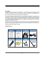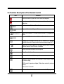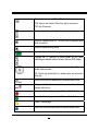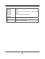
1
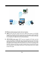
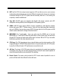
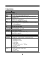
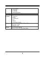
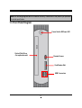
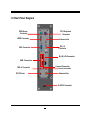
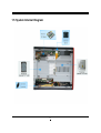
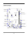
ION-TOP Series User’s Manual No: G03-JC231C98-F Manual revision: 1.0 Release Date:October 21, 2010 i User’s Notice Copyright of this manual belongs to the manufacturer. No part of this manual, including the products and software described in it may be reproduced, transmitted or translated into any language in any form or by any means without written permission of the manufacturer. This manual contains all information required for the utilization of this product to meet the user’s requirements. But it will change, correct at any time without notice. Manufacturer provides this manual “as is” without warranty of any kind, and will not be liable for any indirect, special, incidental or consequential damages (including damages for loss of profit, loss of business, loss of use of data, interruption of business and the like). Products and corporate names appearing in this manual may or may not be registered trademarks or copyrights of their respective companies, and they are used only for identification or explanation and to the owner’s benefit, without intent to infringe. Package Contents ii Safety Instruction Operate the product according to the correct installation steps and with great care to make sure safety and comfort using experience. Please refer to the following safety instruction guide to avoid danger of electric shock or fire. Abide by the previous safety instruction guide to use and maintain the product and the hard disk to make sure of safe operating environment. Please follow the instruction manual for operation guide. The appropriate operating temperature ranges from 0 °C–35 °C (32 °F–95 °F) The operation humidity for this product is 5% to 80% RH. To avoid high temperature, please DO NOT overload the maximum power of the external power supply while the system is consuming high voltage. Be aware of the maximum temperature allowance of the power supply. See to it that the product is not working near the water. Always unplug power cable and other hardware cables from the system before cleaning. Apply only dry cloth for cleansing the product. Make sure that there is no heat source nearby when the product is working. Make sure that the thermal louver of the product is not blocked. Make sure to remove the power plug from the product when there is a thunder storm. Please remove the power plug from the product when you are not going to use the product for a long time. Make sure to set up or use the product on a stable surface. Make sure not to drop the product or strike it by any means. Make sure not to move the product when the power is on. Make sure not to step on the power cables and other cables or rest anything in them.. Please contact qualified technician for maintenance or repair. Use only accessories and parts that are made by the qualified manufacturer. iii TABLE OF CONTENT USER’S NOTICE ....................................................................................................................... ii PACKAGE CONTENTS ............................................................................................................ ii SAFETY INSTRUCTION ........................................................................................................... iii CHAPTER 1 BRIEF INTRODUCTION 1-1 PRODUCT FEATURES............................................................................................... 1 1-2 SPECIFICATION ......................................................................................................... 4 1-3 FRONT PANEL DIAGRAM ......................................................................................... 6 1-4 REAR PANEL DIAGRAM ........................................................................................... 7 1-5 SYSTEM INTERNAL DIAGRAM................................................................................. 8 1-6 MOTHERBOARD DIAGRAM...................................................................................... 9 CHAPTER 2 HARDWARE INSTALLATION 2-1 TO REMOVE THE COVER ......................................................................................... 10 2-2 TO INSTALL MEMORY MODULE.............................................................................. 11 2-3 TO INSTALL MINI-PCIE CARD AND WIFI ANTENNA.............................................. 12 2-4 TO INSTALL OPTICAL DISK DRIVER AND HARD DISK DRIVER.......................... 14 2-5 TO RESTORE REMOVABLE CHASSIS COVER ...................................................... 17 CHAPTER 3 SYSTEM OPERATION 3-1 FRONT PANEL CONNECTION .................................................................................. 18 3-2 REAR PANEL CONNECTION .................................................................................... 19 3-3 REMOTE CONTROL DIAGRAM ................................................................................ 25 3-4 FUNCTION DESCRIPTION OF THE REMOTE CONTROL....................................... 26 APPENDIX NOTICE ..................................................................................................................... 29 iv Chapter 1 Brief Introduction 1.1 Product Features Thank you for purchasing ION-TOP, a new product developed, designed and manufactured under leading technical power and consistent dedication to fine workmanship. ION-TOP is a product to provide you HTPC enjoyment and stunning game-playing experience. It can also serve as home server for data gathering with its expandable Wi-Fi function. ION-TOP is not just a general barebone system, but a powerful system with competitively advantage in: HTPC Experience: ION-TOP system supports VGA, DVI and HDMI connector, optical SPDIF W/192KHz Audio output and true 1080P high resolution video playback with integrated ION Graphic processor. The powerful chipset ensure you brilliant video playback without lag while CPU usage rate is pretty low. Game-Playing: ION-TOP support s most of the online games and PC games with smooth playback better to that of average configured personal computers available in current market while CPU usage rate is much lower. Homer Server: IOP-TOP can work as WiFi home server in family with WiFi antenna attached. With this WiFi network, computer in different room of the house can easily realize data sharing. You can easily access to the downloaded HD movies stored in the HDD of the ION-TOP, or watching other shared videos stored in your PC via this function on high definition screen. 1 ION-TOP has the following features besides other basic functions: HDMI: ION-TOP series HTPC systems come with an HDMI output connector to Full HD1080P high-definition multimedia home theatre enjoyment. User can enjoy seamless playback of HD DVD and Blu-ray disk in the living room by connecting ION system to LCD TV set with an HDMI cable for non-compressed, full digital audio and video movie transmission. SPDIF W/192KHz Audio output: ION-TOP series are integrated with HD audio codec that supports optical SPDIF OUT 192KHz/24bit, auto detecting Peripheral devices and multi-streaming technology that transferring audio signals in different directions. With this function you can enjoy playing games with multi-channel audio effect and talking to your friend with a microphone at the same time. It makes you feel that you were right on the scene when you are watching HD movies with its multi-channel Hi-visual dramatic audio output. All these thrilling functions can be realized with this HTPC system. 2 WiFi: the Mini PCI-E slot onboard socket supports a WiFi card that can act as a mini wireless modem when external antennas are connected. Different computers in the house can via wireless connections through the ION TOP system and take necessary data from it, thus reducing the complexity in network establishment. Giga LAN: ION-TOP series are integrated with Gigabit LAN network controller with ACPI management realizing efficient power management for the operating system. USB2.0: ION-TOP series support USB 2.0 function compatible for both Next-Gen interface devices and present USB 1.1 interface devices. Users can enjoy high speed data transmission rate up to 480Mb/s. Users can also connect USB 2.0 storage device to the ION system via USB cable to create a data bank for storage of download movies. MMC/SD/MS 3 in 1 card reader: Users can easily insert the MS/SD card to the front MMC/SD/MS 3 in 1 card reader to watch the photos taken or video recorded. User can watch them through LCD TV screen and make certain edition when it is shown. With a LCD TV you can realize better picture quality for the video and photos as well. CPU Usage: The CPU Usage diagram shows a beautiful data curve that indicate a pretty low CPU usage percentage for 1080p HD video playback when running the system with a 24’’ LCD monitor to play files of different formats, GPU performances are excellent as well. dB Value: The design of ION-TOP system takes into consideration the needed quiet operating environment in the living room and the average dB value is below 26 under normal operation to ensure the tranquility when you are absorbed in film watching. Remote Control: The remote control provided for HTPC function makes it possible for users to power on/off and switch from different functions with ease. 3 1.2 Specification Model ION-TOP Series Motherboard Specification CPU Intel® Atom Processor Chipset Intel Pine Trail-D + NM10 Chipset +NV GT218 GPU Memory 2 * 240-pin DIMM Sockets for un-buffered Single Channel DDRII 800/667 SDRAM up to 4 GB Ethernet LAN Realtek 8111DL 10/100/1000 LAN Mini PCI-E 802.11 b/g/n Wi-Fi card (optional) Audio Realtek ALC662 6-Channel HD Audio CODEC Storage 4 * Serial ATA2 3Gb/s connectors (SATA 3 & 4 Support RAID 0, 1, JBOD) 1 * eSATA port (External) USB Embedded 7 * USB 2.0 BIOS AMI Flash ROM Write Protect M/B Form Factor Mini-ITX Form Factor, 170 x 170mm Barebone Specification Product size 210(W) x 258(D) x 65(H)mm Devices Exposed 1 * Slim ODD Drive / 2.5”SATA HDD Drive Bay Slim ODD drive (optional) Colors Black or White color, depending on the model purchased System Fan Side: 6cm Fan SLEEVE * 1 Front I/O Port 2 * USB 2.0 & 1 * SD/MS card reader & Remote control sensor Rear I/O Port 4 * USB 2.0 ports 1 * PS/2 Mouse connector 1 * PS/2 Keyboard connector 1 * RJ-45 LAN port 1 * Audio I/O port 1 * VGA port & 1 * DVI-D port & 1 * HDMI port 1 * 12V DC in connector 1* E-SATA port Internal I / O 2 * USB 2.0 headers for 3 * USB 2.0 ports 3* FAN headers 1 * CD IN /1 * GPIO 4 Power supply Standard Accessories Packing Certificate 1 * AUDIO header 1 * CIR header 1 * COM header 1 * MINI PCI-E connector Onboard DC-DC Power supply 1 * AC-DC Power Adapter 1 * Power Cord 4 * Stands 1 * Remote control 1 * CD 1 * Manual 1 * WiFi Antenna (optional) Color Box Dimension:417(W) x 137(D) x 296(H)mm Gross Weight:3.65KG Net Weight:3.02KG CE,FCC RoHS For Barebone CE, FCC, TUV, UL, CCC, CB For Power Adapter 5 Note:The following diagrams are for illustration use only. Please refer to the product you purchase for actual specification. 1.3 Front Panel Diagram Power Switch W/Power LED Optical Disk Driver --for optional model Remote Sensor Card Reader Slot USB Connectors 6 1.4 Rear Panel Diagram PS/2 Mouse Connector PS/2 Keyboard Connector HDMI Connector Antenna hole DVI –D Connector VGA Connector RJ-45 LAN Connector USB Connectors Line-out Connector Line-in connector MIC-in Connector Antenna Hole DC12V Jack E-SATA Connector 7 1.5 System Internal Diagram 8 1.6 Motherboard Diagram JP1 CPUFAN1 Keyboard & Mouse Connector HDMI Connector Intel ATOM CPU SYSFAN1 DDRII DIMM Slot x2 (DDRII 800 / DDRII 667) DVI1 Port Over VGA Port NV GT218 GPU USB Port Connector RJ-45 over USB Connector Audio Connector DC 12V Power Connector CDIN Header JP4 Intel NM 10 Chipset Power Connector Gigabit PCI-E LAN Chip ALC 662 Audio Codec SATAII Connectors (SATA1~SATA4) CIR Mini-PCIE Slot GPIO_CON USB2 JP6 Front Panel SYSFAN2 Audio Header JP5 Power LED COM1 Header JBAT USB3 9 Speaker Header 8 Mbit DPI Flash Rom BIOS Front Panel Header Chapter 2 Hardware Installation NOTE! Photos in the manual are use to show users how to install hardware in a standard practice only and the model in manual may differ from actual product. Please refer to the product you purchased for actual specification. 2-1. To Remove the Cover 1. To remove the top cover from chassis, please remove the two screws on the back panel at first. 2. Push the top cover towards to the rear panel. 3. Open up the top cover. 10 4. Remove the screws from the ODD/HDD bracket with a screwdriver. 5. Get the bracket out of the chassis before installing memory modules and other devices to the board inside. 2-2.To Install Memory Module Notch on the module Break point on the slot 1. Unlock the slot by pushing outwards the 2. eject tabs and then push the module in the right direction downwards vertically. 11 When installing, align a module on the slot that the notch on the module matches the break on the slot. Memory module can not be installed in such a direction. If not, it will cause serious damage to module and the board. NOTE! When you install DIMM module fully into the DIMM socket the eject tab should be locked into the DIMM module very firmly and fit into its indention on both sides. 2-3. To Install Mini-PCI-E Card and WiFi Antenna 1. The WIFI card. 2. 3. Insert the gold figure side of the compatible 4. Mini-PCI-E card into the Mini-PCI-E slot by a 45 angle. 12 WIFI antenna connector. Then tighten up the two screws to make sure that the mini-PCIE card locked to the board. 5. Press the metal hat on the other end of the antenna connector into the antenna slot (ANT1) on the mini-PCIE card as shown. 6. Locate the RF slot for WIFI antenna connector in the rear panel. 7. Tighten one hexagonal bolt onto the end of the antenna connector and fit a washer at this end. 8. Fit the antenna connector into the RF slot from inside the chassis and then lock it into the panel by tightening another hexagonal bolt from the outside. 13 9. Connect the external WIFI receiver to the antenna connector on the rear panel. 2-4. To Install Optical Disk Driver and Hard Disk Driver 1. Install the optical drive disk to the appropriate position and then lock the screws with a screwdriver. 14 2. Put the 2.5 inch SATA HDD on the bracket with this side up. 3. Fasten the HDD to the bracket by locking the screws in the marked places with a screwdriver. 4. Pull the bracket with ODD and HDD locked with screws on it into the ODD/HDD bay. 5. Lock the ODD/HDD bracket to the chassis by locking the screws in the marked places with a screwdriver. 15 SATA hard disk cable Optical driver disk cable SATA hard disk power cable 6. The attached SATA-SLM ODD cable and SATA power cable has been pre-installed in the chassis. User only needs to connect the above cable connector to respective devices. 7. Connect the ODD power cable to the ODD. 8. 16 Connect SATA cable and SATA power cable to the SATA disk. 2-5. To Restore Removable Chassis Cover 1. Slide the top cover into the chassis and put it 2. in the direction towards the front panel (Make sure that the six metal hooks of the cover be fit into corresponding little slots in the chassis to make sure it firmly locked). 17 Lock the two big screws on the rear panel to its original place until it firmly locked. Chapter 3 System Operation After needed hardware installed inside the chassis, you can proceed on to connect cables to the rear panel and power on the system to enjoy the using ION-TOP. 3.1 Front Panel Connection Power on Switch W/Power LED Optical Disk Driver (for optional model) Remote Sensor Card Reader Slot USB Connectors USB Connectors: to connect USB mouse, keyboard and other USB storage device to the system. Card Reader Slot: to insert the MMC/SD /MS card to the card reader on front panel. Remote Sensor: to receiver signals from remote control. Optical Disk Driver: to watch movies on the DVD (Optical disk driver only comes with optional model). Power on Switch: after needed hardware installed and correct configuration made, you can power on the system to enjoy multi-functions ION-TOP brings to you. 18 3.2 Rear Panel Connection PS/2 Mouse Connector: The connector is used for PS/2 mouse connector. PS/2 Keyboard Connector: The connector is used for PS/2 keyboard connector. 19 VGA Connector: VGA connector is the 15-pin D-sub female connector; it is for the display devices, such as the CRT monitor, LCD monitor and so on. DVI (Digital Visual Interface) Connector: This interface standard designed to maximize the visual quality of digital display devices such as flat panel LCD computer displays and digital projectors. 20 HDMI (High-Definition Multimedia Interface) Connector: This point-to-point interface is for audio and video signals designed as a single-cable solution for home theater and consumer electronics equipment. USB Connectors: There are 4 USB connectors on rear IO panel to connect USB mouse, keyboard and other USB devices to the system. 21 RJ-45 Connector: The connector is standard RJ-45 connector for Network. Please connect to the network cable to this connector. Line-In: This is a line-in connector for user to connect external audio device. 22 Line-Out / Optical SPDIF out shared Connector: Connect stereo speakers or headphones for audio outputor to connect Realtek 6-Channel HD Audio CODEC w/ SPDIF out audio output device for superior audio enjoyment. Mic-In Connector: User can connect microphone to this port. 23 E-SATA Connector: Use E-SATA cable to connect E-SATA hard disk to the system. DC12V Jack: Connect the power adapter to DC12V jack after connecting connector power cord to adapter. Then Turn on the system either by power switch on front panel or remote control when all necessary configuration are made. 24 3.3 Remote Control Diagram The accessories of ION-TOP include a remote control with which you could easily carry out a lot functions to bring your friendly user-experience during HTPC watching and other functions for your contingency.. 25 3.4 Function Description of the Remote Control Icon Function Press the button to power on or shut down the computer. Records a selected television program and stores it on the hard disk drive. PRINT GUIDE RECORDER TV RADIO Prints an item in Windows Media Center. Opens the Television Program Guide. Opens the Recorded TV window where recorded TV programs are listed. Opens the FM Radio window in Windows Media Center. Displays the full-screen view of live TV. Moves a TV program forward to the end of the pause buffer and resumes playing live TV. Opens the Play DVD window in Windows Media Center or opens the main menu of a DVD movie, if available. Moves the media backward at three speeds. Plays the selected media. Moves media forward at three speeds. Rewind the position pointer an increment;CD and Playlist, rewind to previous song; DVD, rewind to previous chapter; Slide show, rewind to previous picture; PVR, rewind 7 seconds Pauses audio and video tracks and live or recorded TV programs. 26 Skip ahead an increment; CD and Playlist, skip to next song; DVD, skips to next chapter; Slide show, skip to next picture; PVR, skip 29 seconds Increases (+) and decreases (-) volume. Turns off computer sound off. The word Mute is displayed when Mute is turned on. Stops the media currently playing. Opens the Windows Media Center main menu. Changes the TV channels or moves pages up and down, depending on available options. Moves to the next DVD chapter. Moves the cursor to navigate and select actions within all Windows Media Center windows. OK - Selects the desired action or window option and acts as the Enter key. Returns to the previous window within Windows Media Center. Displays available information about a selected media file and displays other menus. Opens the Videos Library window in Windows Media Center. Opens the Music Library window in Windows Media Center. Opens TV Home page. Opens the Pictures Library window in Windows Media Center. 27 Enters text and numbers into a Windows Media Center search or text box. Each time you press a number button, a different character appears. Press the button Enter to select a character. Selects the desired action, menu, or window option. Deletes the last character entered. 28 Appendix Notices General Notices European Union CE Marking and Compliance Notices Products intended for sale within the European Union are marked with the Conformity European (CE) Making, which indicates compliance with the applicable Directive and European standards and amendments identified. Shielded Cables Notice All connections to other computing devices must be made using shielded cables to maintain compliance with FCC regulations. Peripheral Devices Notice Only peripherals (input/out devices, terminals, printers, etc) certified to comply with Class B limits may be attached to this equipment. Operation with non-certified peripherals is likely to result in interference to radio and TV reception. Optical Disk Drive Notice The optical disk drive is Class 1 Laser Product. Wireless Related Information Wireless Interoperability Wireless LAN PCI Express Mini Card is designed to be interoperable with any wireless LAN product that is based on Direct Sequence Spread Spectrum (DSSS), Complementary Code Keying (CKK), and/or Orthogonal Frequency Division Multiplexing (OFDM) radio technology, and is compliant to: The IEEE802.11a/b/g Standard on Wireless LANs was defined and approved by the Institute of Electrical and Electronics Engineers. The Wireless Fidelity (WiFi) certification as defined by the Wi-Fi Alliance. Usage Environment and Your Health Wireless LAN PCI Express Mini Card emits radio frequency electromagnetic energy like other radio devices. However, the level of energy emitted is far much less than the electromagnetic energy emitted by wireless devices like for example mobile phones. 29 Due to the fact that Wireless LAN PCI Express Mini Card operates within the guidelines found in radio frequency safety standards and recommendations, we believe the integrated wireless cards are safe for use by consumers. These standards and recommendations reflect the consensus of the scientific community and result from deliberations of panels and committees of scientists who continually review and interpret the extensive research literature. In some situation or environment, the use of Wireless LAN PCI Express Mini Card may be restricted by the proprietor of the building or responsible representatives of the organization. These situations may for example include: Using the integrated wireless cards on board of airplanes, or in hospitals In any other environment that the risk of interference to other devices and service are perceived or identified to be harmful. If you are uncertain of the policy that applies on the use of wireless devices in a specific organization (e.g., airport or hospital), you are encouraged to ask for authorization to use Wireless LAN PCI Express Mini Card prior to turning on the computer. Electronic Emissions Notices European Union Compliance Statement Class B Compliance European Union – Compliance to the Electromagnetic Compatibility Directive This product is in conformity with the protection requirements of EU Council Directive 2004/108/EC on the approximation of the laws of the Member States relating to electromagnetic compatibility. We cannot accept responsibility for any failure to satisfy the protection requirements resulting from a non-recommended modification of the product, including the installation of option cards from other manufacturers. This product has been tested and found to comply with the limits Class B Information Technology Equipment according to European Standard EN55022. The limits for Class B equipment were derived for typical residential environments to provide reasonable protection against interference with licensed communication devices. 30 Properly shielded and grounded cables and connectors must be used in order to reduce the potential for causing interference to radio and TV communications and to other electrical or electronic equipment. FCC Rules and Regulations-Part 15 This devices uses, generates and radiates radio frequency energy. The radio frequency energy produced by this device is well below the maximum exposure allowed by the Federal Communications Commission (FCC) z This device complies with the limits for the Class B digital device pursuant to Part 15 subject to the following two conditions: z This device may not cause harmful interference. z This device must accept any interference received, including interference that may cause undesired operation. The FCC limits are designed to provide reasonable protection against harmful interference when the equipment is installed and used in accordance with the instruction manual and operated in a commercial environment. However, there is no guarantee that interference will not occur in a particular commercial installation, or if operated in a residential area. If harmful interference with radio or television reception occurs when the device is turned on, the user must correct the situation at the user’s own expense. The user is encouraged to try one or more of the following corrective measures: z Re-orient or relocate the receiving antenna. z Increase the separation between the equipment and receiver. z Connect the equipment into an outlet on a circuit different from that on which the receiver is connected. z Consult the dealer or an experienced radio/TV technician for help. CAUTION: The Part 15 radio device operates on a non-interference basis with other devices operating at this frequency. Any changes or modification to said product not expressly approved by Intel could void the user’s authority to operate this device. 31