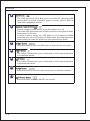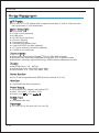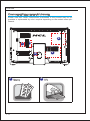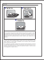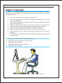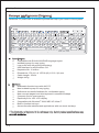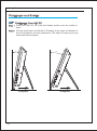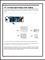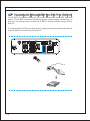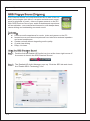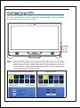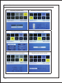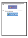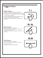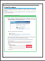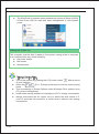
1
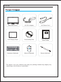
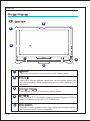
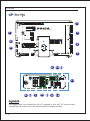
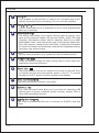
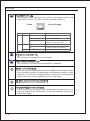
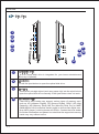
LEAF TOUCH PC
USER MANUAL
Preface
TABLE OF CONTENTS
1. Overview.............................................................................................. 1-1
Packing Contents ............................................................................................ 1-2
System Overview ............................................................................................ 1-3
Mainboard Specifications ................................................................................ 1-9
System Specifications .....................................................................................1-10
Component Replacement & Upgrade ............................................................1-11
2. Getting Started .................................................................................... 2-1
Safety & Comfort tips ....................................................................................... 2-2
Having Good Working Habits .......................................................................... 2-3
Knowing the Keyboard (Optional)................................................................... 2-4
Positioning your system .................................................................................. 2-6
Connecting Peripheral Devices ....................................................................... 2-7
Connecting Power ......................................................................................... 2-12
3. System Operations .............................................................................. 3-1
System Booting Setup for the first time........................................................... 3-2
SRS Premium sound (Optional) ..................................................................... 3-3
On- Screen Display (OSD)............................................................................... 3-5
Multi-Touch Gesture ...................................................................................... 3-8
Power Management ........................................................................................ 3-9
Chapter 1
Overview
Beanstalk Ultima is integrated in design, selecting a stylish appearance with a glassy frame, which displays the simplicity of
modern individualism and the comfort of home. Furthermore, it
is accompanied with the best computer features, such as instant
message, low acoustics, energy saving and 802.11 b/g/n wireless internet capability so you may roam freely in the realm of
cyberspace.
Overview
PACKING CONTENTS
Beanstalk Series
AC/ DC Adapter
AC Power Cord
LCD Display Wiper
Driver/Utility Disk
User Manual &
Quick Guide
Keyboard (Optional)
Mouse (Optional)
Stylus (Optional)
* The picture is for your reference only and your packing contents may slightly vary
depending on the model you purchased.
1-2
Overview
SYSTEM OVERVIEW
Front View
2
1
4
3
5
1
Microphone
- The built-in microphone can be used for video chatting online.
2
Webcam
- The built-in webcam with the microphone can be used for picture taking, video recoding, online conferencing and any other interactive applications.
3
IR Receiver (Optional)
- This infrared receiver is provided for remote control.
4
LCD Display
5
Stereo Speakers
- The 21.5-inch TFT LCD display is with an optimal resolution of 1920 X
1080 and standard proportion of 16:9 widescreen.
- The built-in stereo speakers deliver high quality sound blaster with stereo system and Hi-Fi function supported.
1-3
Overview
Rear View
1
1
2
4
3
5
1
8
12
11
6
7
8
9
10
Important
We suggest that you connect the AC/ DC adapter to your AIO PC first and then
connect the AC power cord to the socket-outlet for safety concerns.
1-4
Overview
1
Ventilator
- The ventilator on the enclosure is used for air convection and to prevent the equipment from overheating. Do not cover the ventilator.
2
Optical Disk Drive
3
Card Reader Drive
- A DVD Super-Multi drive is integrated for your home entertainment
(Blue-ray is optional).
- The built-in card reader may support various types of memory card,
such as XD (eXtreme Digital), SD (Secure Digital), SDHC (SD High
Capacity), MS (Memory Stick), MS Pro (Memory Stick Pro) or MMC
(Multi-Media Card) cards that usually used in devices like digital cameras, MP3 players, mobile phones and PDAs. Contact the local dealer
for further information and please be noted that the supported memory
cards may vary without notice.
4
Stand
5
Cable Routing Hole
- Use this stand to position your system on a fat and stable surface.
- Route the cables through the cable routing hole to avoid cable spaghetti when connecting devices.
6
Power Jack
- The power adapter converts AC power to DC power for this jack. Power supplied through this jack supplies power to the PC. To prevent
damage to the PC, always use the supplied power adapter.
7
VGA - In Port (Optional)
The DB15-pin female connector is provided.
8
USB Port
- The USB (Universal Serial Bus) port is provided for attaching USB
devices such as mouse, keyboard, printer, scanner, camera, PDA or
other USB-compatible devices.
9
E-SATA Port (Optional)
The E-SATA (External-SATA) port is provided for E-SATA hard disk
drives.
1-5
Overview
10
RJ-45 LAN Jack
- The standard RJ-45 LAN jack is provided for connection to the Local
Area Network (LAN). You can connect a network cable to it.
Yellow
LED
Color
LED State
Condition
Left
Yellow
Off
LAN link is not established.
On (steady state)
LAN link is established.
On (brighter & pulsing)
The computer is communicating with
another computer on the LAN.
Off
10 Mbit/sec data rate is selected.
On
100 Mbit/sec data rate is selected.
On
1000 Mbit/sec data rate is selected.
Right
Green
Orange
11
Green/ Orange
Microphone Connector
- This connector is provided for microphones.
12
Audio Output Connector
- This connector is provided for headphones or speakers.
HDMI - In Port (Optional)
- The High-Definition Multimedia Interface (HDMI) is an all-digital audio/
video interface capable of transmitting uncompressed streams. HDMI
supports all TV format, including standard, enhanced or high-definition
video, plus multi-channel digital audio on a single cable.
TV Tuner Antenna Connector (Optional)
- This connector is for TV antenna.
Optical S/PDIF-Out Jack (Optional)
- This S/PDIF (Sony & Philips Digital Interconnect Format) jack is provided for digital audio transmission to external speakers through an
optical fiber cable.
1-6
Overview
Side View
1
2
3
6
4
5
8
10
11
1
Optical Disk Drive
- A DVD Super-Multi drive is integrated for your home entertainment
(Blue-ray is optional).
2
Eject Button
- Press the eject button to open the optical disk drive.
3
Eject Hole
- Insert a thin, straight object (such as a paper clip) into the eject hole to
open the optical disk drive manually if the eject button does not work.
4
Card Reader Drive
- The built-in card reader may support various types of memory card,
such as XD (eXtreme Digital), SD (Secure Digital), SDHC (SD High
Capacity), MS (Memory Stick), MS Pro (Memory Stick Pro) or MMC
(Multi-Media Card) cards that usually used in devices like digital cameras, MP3 players, mobile phones and PDAs. Contact the local dealer
for further information and please be noted that the supported memory
cards may vary without notice.
1-7
7
9
Overview
5
USB Ports
- The USB (Universal Serial Bus) port is provided for attaching USB
devices such as mouse, keyboard, printer, scanner, camera, PDA or
other USB-compatible devices.
6
System Power Button/LED
- Press the system power button to turn the system on or off.
The power LED glows when the system is turned on and goes off when
the system is shut down.
In terms of power saving, the LED blinks in S3 (Suspend to RAM)
mode and goes off in S4 (Suspend to Disk) mode. Pressing the system
power button will wake the system up from power saving mode.
7
MENU Button
- Press this button to view the OSD menu or enter into the sub menu.
8
Right Button
- This button indicates the cursor movement or OSD manual selection
in incremental values.
9
Left Button
- This button indicates the cursor movement or OSD manual selection
in decremental values.
10
AUTO Button
- Press this button to view the video mode menu or exit the submenu.
11
LCD Power Button
- Press this button to power ON/OFF the monitor.
1-8
Overview
MAINBOARD SPECIFICATIONS
Processor
■Socket 478 for Intel® Pentium® Dual-Core or Celeron® and CoreTM2 Duo processors
■Front Side Bus (FSB) up to 1066 MHz
■Thermal Design Power (TDP) 35 W
Chipset
■NVIDIA® ION (MCP7A-LP) chipset
■Thermal Design Power (TDP) 17 W
Memory
■2 DDR2 667/ 800 SO-DIMM slots (200 pins/ 1.8V)
■Supports the maximum of 8 GB
LAN
■Gigabit Fast Ethernet by Realtek® 8111DL GbE controller
Audio
■HDA Codec by Realtek® ALC888
■Compliant with Azalia 1.0 specs
Form Factor
■197mm x 210mm
1-9
Overview
SYSTEM SPECIFICATIONS
LCD Display
■21.5-inch TFT LCD display with an optimal resolution of 1920 X 1080 and standard proportion of 16:9 widescreen
Input / Output (I/O)
■1 DC power jack
■1 VGA-In port (optional)
■6 USB ports
■1 E-SATA port (optional)
■1 RJ-45 LAN jack
■1 microphone jack
■1 headphone/ speaker jack
■1 optical S/PDIF-out jack (optional)
■1 TV tuner antenna connector (optional)
■1 HDMI-In port (optional)
Communication
■Wired LAN: supported by Realtek® RTL8111DL GbE controller
■Wireless LAN: optionally supported through Mini PCI-E WLAN module
■Bluetooth: optionally supported through USB-interfaced Bluetooth module
Storage
■Hard Disk Drive: 3.5”, SATAII
■Optical Disk Drive: Slim DVD Super Multi
■Card Reader: 4 in 1 (XD, SD, MMC, MS)
Stereo Speaker
■2 Hi-Fi stereo speakers with SRS Premium Sound (5 W x 2)
WebCam
■1.3M WebCam with microphone
Power Supply
■120 watt AC/ DC adapter with active PFC
■Input: 100-240V~, 50-60Hz, 2.0A
■Output: 19V
6.3A
Built-In Card
■1 wireless LAN card
Dimension
■ 513 mm (W) X 392 mm (H) X 91 mm (D)
1-10
Overview
COMPONENT REPLACEMENT & UPGRADE
Please note that certain components preinstalled in the product may be upgradable or replaceable by user’s request depending on the models users purchased.
5
1
2
3
4
1 Memory
1-11
2 CPU
Overview
3 Hard Disk Drive
4 Wireless LAN Card
5 Optical Disk Drive
If the specified component has been determined by the HCL engineer or store
as problematic or defective and may incur the need for replacement, you may
bring the product for repair along with the warranty card, purchase invoice or
receipt to the HCL-authorized service center closest to your location for assistance.
To learn more about upgrade limitation, please refer to the specifications in the
User’s Manual. For any further information on the product users purchased,
please contact the local dealer.
Do not attempt to upgrade or replace any component of the product if you are not
an authorized dealer or service center, since it may cause the warranty void. It is
strongly recommended that you contact the authorized dealer or service center
for any upgrade or replace service.
1-12
Chapter 2
Getting Started
This chapter provides you with the information on hardware setup procedures. While connecting peripheral devices, be careful
in holding the devices and use a grounded wrist strap to avoid
static electricity.
Getting Started
SAFETY & COMFORT TIPS
The AIO PC is a portable platform that allows you to work anywhere. However,
choosing a good workspace is important if you have to work with your PC for a
long period of time.
■ Your work area should have enough illumination.
■ Choose the proper desk and chair and adjust their height to fit your posture when operating.
■ When sitting on the chair, adjust the chair’s back (if available) to support
your back comfortably.
■ Place you feet flat and naturally on the floor, so that your knees and elbows have the proper position (about 90-degree) when operating.
■ Put your hands on the desk naturally to support your wrists.
■ Adjust the angle/position of the AIO PC to have an optimal view.
■ Avoid using your PC in a place where discomfort may occur (such as on
the bed).
■ The AIO PC is an electrical device. Please treat it with great care to avoid
personal injury.
1. Keep your hands and feet with optimal comfort.
2. Adjust the angle and position of the monitor.
3. Adjust the desk’s height.
4. Sit straight and keep a good posture.
5. Adjust the chair’s height.
2-2
Getting Started
HAVING GOOD WORKING HABITS
Having good working habits is important if you have to work with your AIO PC
for long periods of time; otherwise, it may cause discomfort or injury to you.
Please keep the following tips in mind when operating.
■ Change your posture frequently.
■ Stretch and exercise your body regularly.
■ Remember to take a break after working for a period of time.
2-3
Getting Started
KNOWING THE KEYBOARD (OPTIONAL)
Leaftouch PC packs with a wireless keyboard that helps your control of the system.
Specifications
Compatible with EU/UK/US/JP/KR language layout
Isolated keycap for easy typing
Low profile with silk printing technology
USB interface for all Windows® OS
Keystroke life: 12 million
Dimensions: 376.4 (L) X 155.09 (W) X 21.91 (H) mm
Cable Length: 150cm
Weight: 440g
Features
Multimedia function keys with AIO PC
New isolated keycap for easy typing
Soft-touch and tactile feedback for comfortable typing
New concept elegant and slim keyboard in streamline shape
Compact size for space saving
Especially fit for HCL LCD display
Compatible with Windows® 2000/ ME/ XP/ Vista/ 7
Built-in function hot keys
Access favorite websites and applications with one touch hot keys
* The illustration of keyboard is for reference only. Actual product specifications may
2-4
Getting Started
▶ Multimedia Keys
Fn + F7
Backward to previous track
Fn + F8
Play and pause
Fn + F9
Forward to next track
Fn + F10
Mute function
Fn + F11
Volume down
Fn + F12
Volume up
▶ Hot Keys
2-5
Fn + F1
Launch the default E-Mail applications
Fn + F2
Launch the default internet browser and go to the default home page
Fn + F3
Back to the previous web page
Fn + F4
Forward to the next web page
Fn + C
Calculator
Fn + Z
Sleep mode (energy saving)
Fn + W
Wireless LAN
Fn + K
Camera
Getting Started
POSITIONING YOUR SYSTEM
Positioning Your AIO PC
Step 1. Place your AIO PC on a flat and steady surface such as a table or
desk.
Step 2. Pull the stand open and tilt the LCD display to an angle of between 10
and 20 degrees to suit your preference. This helps to reduce your eye
strain and muscle fatigue.
10°
2 0°
10 degrees
2-6
20 degrees
Getting Started
CONNECTING PERIPHERAL DEVICES
The I/O (input/output) ports on the rear panel allow you to connect peripheral
devices. All devices listed here are for reference only.
Connecting the USB Devices
This AIO PC provides USB ports for connecting various USB devices, such as
mouse, keyboard, digital camera, webcam, printer, external optical storage device,.. and etc. To connect these devices, install the drivers for each device first
if necessary, and then connect the device to the AIO PC. This AIO PC is capable
of auto detecting the USB devices installed, and if there is no detection of the devices, please manually enable the USB devices by going to Start Menu / Control
Panel / Add Hardware to add the new device.
2-7
Getting Started
y
This AIO PC provides VGA ports for connecting larger displays with higher resolution.
The 15-pin-D-sub VGA port allows users to connect an external monitor or other
standard VGA-compatible devices (such as a projector) for a great view of the AIO PC
display.
To connect the external display, make sure the AIO PC and the external display are
both powered off, and then connect the display to the AIO PC.
Once the display is connected to the AIO PC, power on the AIO PC and the external
display should respond by default. If not, you can switch the display mode by pressing
[Fn]+[F2]. Alternately, you can change the display mode by configuring the settings in
Display Properties of Windows operating system.
2-8
Getting Started
Connecting the External SATA Hard Disk Drive (Optional)
The E-SATA Connector allows you to connect an external Serial ATA hard disk
device. The E-SATA standard interface supports “plug-and-play” technology, so
that you can connect and remove the E-SATA devices without turning of the
AIO PC.
To connect the E-SATA hard disk device, simply connect the cable of the device
to the E-SATA Connector of your AIO PC.
2-9
Getting Started
Connecting the Communication Device
2-10
2-11
Getting Started
CONNECTING POWER
Connecting the AC Power
Step 1. Unpack the package to find the AC/DC adapter and AC power cord.
Step 2. Assemble the AC/DC adapter and the AC power cord.
Step 3. Plug the DC end of the adapter to the AIO PC, and the male end of the
AC power cord to the electrical outlet.
Important
We suggest that you connect the AC/DC adapter to your AIO PC first and then
connect the AC power cord to the socket-outlet for safety concerns.
Disconnecting the AC Power
Step 4. Unplug the AC power cord from the electrical outlet first.
Step 5. Unplug the connector from the AIO PC.
Step 6. Disassemble the AC power cord and the AC/DC adapter.
Important
When unplugging the AC power cord, always hold the connector part of the cord.
Never pull the cord directly!
4
1
5
2
3
2-12
6
Chapter 3
System Operations
This chapter provides you with essential information on system
operations, such as system boot setup, recovery disk creation,
network connection, SRS Premium Sound, and so on.
Important
• It is highly recommended that you create a system recovery
disk as the backup solution in the event of a catastrophic disk
failure or other accidents.
• All information is subject to change without prior notice.
System Operations
SYSTEM BOOTING SETUP FOR THE FIRST TIME
For the first-time use, you will need to go over the following steps to start using
your Beanstalk Ultima. The entire booting setup will take you around 30 minutes.
Step 1.
Step 2.
Step 3.
Step 4.
Step 5.
Step 6.
Step 7.
Step 8.
Step 9.
Step 10.
Step 11.
Step 12.
Step 13.
3-2
Windows setup starts running. Please wait until Windows setup finishes
the progress loading.
Select the language of the operating system and click [Next] to continue.
Choose the “Country or region”, “Time and currency”, and “Keyboard
layout” you need. Click [Next] to continue.
Choose a user name for your account and name your computer to distinguish it on the network. Click [Next] to continue.
Set a password for your account to protect your user account from unwanted users. (Leave this field blank if no need for password.) Click
[Next] to continue.
Please read the license terms. Check the “I accept the license terms” box
and click [Next] to continue.
Select [Use recommended settings] for “Help protect your computer and
improve Windows automatically.”
Review your time and date settings. Click [Next] to continue.
Please choose a wireless network you intend to join from the provided
WLAN list. Click [Next] to continue. You may also click [Skip] to skip this
step and set up the WLAN later.
Followingly comes the anti-virus software screen. Click [Agree] to ac cept the license agreement terms and activate the anti-virus software.
Alternatively, choose [No, I do not want to protect my PC.] to proceed
without activating the anti-virus software.
The “Software Installation Menu” pops up. Click [Install] to continue.
The software is being installed. Please do not turn of the computer
when software installation is running. When the progress bar completes
loading, click [Finish] to continue.
The system enters the Windows 7 OS to start its personalized settings.
Get ready to explore your AIO PC after the personalized settings are
done. Have fun with it!
System Operations
SRS PREMIUM SOUND (OPTIONAL)
SRS Premium Sound is a comprehensive suite of state-of-the-art
audio technologies that deliver a superior entertainment experience for playback of music, video and game content on the PC.
With SRS Premium Sound your audio entertainment experience
will sound better - more natural and immersive, with deeper bass,
clearer dialog and outstanding surround sound.
Features:
■ Premium audio experience for music, video and games on the PC
■ Immersive surround sound experience from internal or external speakers
and even headphones
■ Greater volume without degrading audio quality
■ Crystal clear dialog
■ Deep, rich bass
Using the SRS Premium Sound
Step 1. Double-click the Realtek HD Audio tray icon at the lower right corner of
the screen to launch the SRS Premium Sound.
Step 2. The Realtek HD Audio Manager pops up. Click the SRS tab and check
the “Enable SRS® Technology” box.
3-3
System Operations
Step 3. Choose the audio content you are listening to. The SRS Premium Sound
will automatically process the specified audio signals to deliver enhanced
audio performance.
Step 4. The following settings allow for specific control of SRS tuning parameters
and are provided for External Speakers and Headphones.
■
■
■
■
■
■
SRS Center: adjusts the center-channel sound
SRS Space: adjusts the amount and width of the sound stage
TruBass Level: adjusts the bass or low frequencies
TruBass Speaker Size: should be used to select the size of the speakers
Focus Level: adjusts the frequencies that include vocals/voice
SRS Definition: adjusts the high frequencies
CAUTION: These settings are very sensitive and should be used by advanced
users.
3-4
System Operations
ON-SCREEN DISPLAY (OSD)
The on-screen display (OSD) allows you to tune the viewing options of the monitor, such as brightness, contrast, positioning, and language. It can be activated
by buttons at the right side of the monitor.
Step 1. Press the MENU button to bring up the OSD main menu. Use the Right
and Left arrow buttons to select the desired function menu and press the
MENU button to enter. Use the Right and Left arrow buttons to select or
tune the values to suit your personal preferences. After the settings are
done, press the AUTO button to exit.
Adjusting contrast and brightness
3-5
Adjusting color
System Operations
3-6
Adjusting signal source
Adjusting positioning & timeout
Specifying language
Resetting system
Reading system information
Adjusting wide screen mode
System Operations
Step 2. Press the Right & Left arrow buttons to adjust the system volume.
Step 3. Press the AUTO button to view the video mode menu. Use the Right &
Left arrow buttons to select a desired mode and press the AUTO button
to exit after the selection is made.
3-7
System Operations
Multi-Touch Gesture
Rotate Gesture:
Place two separated fingers on the Picture.
Retain one finger in the fixed position, and move
other finger in an arching Motion while maintaining
uniform finger separation.
Left arching motion indicates left rotation, Right
arching motion indicates right rotation.
Gesture ends when both fingers are lifted from
Picture.
Pinch Gesture:
Place two fingers on the Picture.
Slide the finger closer together to zoom-out or
further apart to zoom-in.
Gesture ends when both fingers are lifted from
Picture.
Flick Gesture:
Place one finger on the Picture.
Flick the finger across the Picture in a linear,
continuous motion.
Gesture ends when finger is lifted.
3-8
System Operations
POWER MANAGEMENT
Power management of personal computers (PCs) and monitors has the potential to save significant amounts of electricity as well as deliver environmental
benefits.
To be energy efficient, turn of your display or set your PC to sleep mode after a
period of user inactivity.
Power Management in Windows OS
■ [Power Options] in Windows OS allow you to control the power man-agement features of your display, hard drive, and battery.Go to [Start]
> [Control Panel] > [System and Security].
Then click on the [Power Options] link.
Select a power plan that suits your personal needs. You may also finetune the settings by clicking [Change plan settings].
3-9
System Operations
■ The Shut Down Computer menu presents the options of Sleep (S3/S4)
& Shut Down (S5) for rapid and easy management of your system
power.
Waking the System Up
The computer shall be able to wake up from power saving mode in response
to a command from any of the following:
■ the power button,
■ the mouse,
■ the keyboard.
Energy Saving Tips:
■ Turn of the monitor by pressing the LCD power button
of user inactivity.
after a period
■ Utilize the
(Fn + Z) sleep mode keys to turn into power saving
mode.
■ Tune the settings in Power Options under Windows OS to optimize your
PC’s power management.
■ Install power saving software to manage your PC’s energy consumption.
■ Always disconnect the AC power cord or switch the wall socket of if
your PC would be left unused for a certain time to achieve zero energy
consumption.
3-10