1
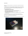
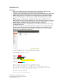
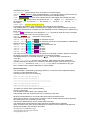
Geosignal ™
Datalogger XT 102 USB
Version 1.2.6
User Manual
Table of Contents
INTRODUCTION...............................................................................................4
GETTING STARTED.........................................................................................5
MEMORY STRUCTURE....................................................................................8
CALIBRATION................................................................................................10
TROUBLESHOOTING....................................................................................12
TECHNICAL SPECIFICATIONS.....................................................................13
Geosignal XT 102 USB Data Logger
Copyright 2013 - 2015 all rights reserved.
www.geosignal.com.au
2
Geosignal XT 102 USB Data Logger
Copyright 2013 - 2015 all rights reserved.
www.geosignal.com.au
3
Introduction
Thank you for purchasing a data logger XT 102 USB (thumb drive standard alone temperature
data logger).
XT 102 is a single channel stand alone temperature data logger storing up to 37435 measures
on its internal memory, it is implemented as generic USB disks and is designed to operate under
any computer operating system capable to read standard USB flash drives (pen drives).
Some of the features XT 102 are:
• One analog channel with 10 bit resolution.
• Double calibration for maximum precision.
• Multiple starts with separate timestamps for each sampling section.
• Text file output compatible with common software like Open Office and Excel.
• Memory erasing protected by password.
• Programmable sampling interval from one second to one week.
• 3V CR2032 lithium battery (not included) or two 1.5V AAA battery (optional) or rechargeable
VR 2020 (optional),
XT 102 does not need a specific software for data downloading and programming, as
programming is done by editing a text file “CONTROL.TXT” which is found in the disk itself.
Data is saved on a read only file named “DATALOGS.CSV”
The data logger will start scan at the given time with the given scan rate after it will be detached
from the USB socket.
Geosignal XT 102 USB Data Logger
Copyright 2013-2015 all rights reserved
www.geosignal.com.au
4
Getting Started
Initialising
•
Make sure a battery has been inserted in the rear slot of the data logger with the
positive + facing down (battery has to be purchased separately).
•
The data logger is password protected and needs to be initialised before use. Each data
logger has a different password (code) which is required for erasing and initialising.
•
Please keep the code in a safe place as it is always required for erasing the memory.
•
Connect the data logger to a USB socket of a USB host enabled device (PC, tablet,
etc).
•
The data logger will appear like a USB disk storing two files: CONTROL.TXT and
DATALOGS.CSV. Open the file CONTROL.TXT with a simple text editor. If your system
does not have a native text editor please install one before using the logger. We have
tested Notepad on Windows, Gedit on Ubuntu, and Ted on Android 4.0.
•
Some Android devices do not immediately open USB drives and require a specific app
to manage USB drives.
•
Some Mac versions try to write hidden files on the logger memory: If this happens the
logger will not allow that and an error message is produced. In this case Mac users
should install a “Virtual Machine” (VirtualBox) running Windows or Ubuntu images to
prevent error messages from the Mac OS.
•
The file CONTROL.TXT on a XT 102 will appear as below:
GEOSIGNAL USB DATA LOGGER
SN:00000001
MEMORY: code?
DATE: 15Y/01M/01D Th
TIME: 12H:00M:48S
SCAN RATE: 00s
START TIME: 01M/01D 12H:00M:30S Th
CLOCK: +000
SENSOR: 025.00C+000
Edit values and save file to program them.
Do not change position and length of fields.
Detach and plug device to show actual programmed values.
Log starts at Start Time after device is detached from USB.
Scans: 00s 01s 10s 01m 10m 01h 01d 01w
Clock +-sec per week
Sensor +-0.1°C (0.18°F)
Input code to unlock device.
Geosignal XT 102 USB Data Logger
Copyright 2013-2015 all rights reserved
www.geosignal.com.au
5
•
•
•
•
(Note: Above colours are not shown on the file; they are only for clarity)
Replace the line “MEMORY: code?” with “MEMORY: xxxxx” where xxxxx is the 5 digit
code specific to your data logger. For example if your code is 01234, type:
“MEMORY: 01234”
Save the file to activate the code: the red LED of the data logger will quickly flash for a
few seconds and the data logger will restart. (The LED is located on the right side near
the USB plug).
Close and and reopen the file CONTROL.TXT. Now, if the code was correct, it will read:
“Memory: 00000” indicating that the memory is blank and the device ready.
Programming
•
Each time the data logger is plugged into a USB socket and CONTROL.TXT is read by
the computer operating system: the data logger reads its memory, registers and sensor
and changes the information contained in CONTROL.TXT. Please NOTE: we have
found that after the data logger has been inserted into a USB socket, all the different
operating systems (we have tested) read the file just ONCE.
•
Please note that the logger is not USB powered, so battery is intensively used during
USB connection. Do not forget to remove the logger from USB after programming.
•
Open CONTROL.TXT and edit the scan rate, current time, and starting time; do not
change position and length of the fields; for example: “DATE: 15Y/01M/01D Th” must
not be changed in “DATE: 15Y/1M/1D Th”
•
Possible scan rates are: 01s 10s, 01m, 10m, 01h, 01d, 01w (00s means stop)
•
Save the file, the data logger LED will blink.
•
If the data logger LED did not blink the file was not really saved, but it is just temporarily
stored in the computer cache. This behaviour depends on the operating system.
Windows and Ubuntu immediately save the file but some other operating systems or
older versions may require you to unmount the device or go through the process of
“Safely remove the device”.
•
Please also note that the data logger internal time is programmed into the data logger
in the precise moment the red LED blinks.
•
Detach the data logger to start the acquisition.
•
If the starting time is past the data logger will start immediately, if the weekday is
incorrect the logger will wait indefinitely to start even if the starting time is past.
•
If you instead only wanted to stop the data logger then you should have programmed
the scan rate as: “SCAN RATE: 00s”
•
At scan time the red led will blink for an instant.
Downloading Data
•
Plug the data logger into any USB socket of a computer.
•
If the logger shows “SCAN RATE: pgm” that indicates it is still waiting for the first scan.
•
Scan will stop and will be resumed once the data logger is detached.
•
Copy the file DATALOGS.CSV from the disk drive to your computer and open it with a
text editor, or Open Office, or Excel.
•
Make sure the data has been actually copied onto your computer hard disk before
erasing the data logger memory.
Erasing memory
•
Plug the data logger into any USB socket of a computer.
•
Do not try to erase directly the file DATALOGS.CSV as it will only be removed from the
computer cache, not from the memory of the data logger.
•
Open the file CONTROL.TXT with a text editor,
•
Replace the line “MEMORY: 37435” with “Memory: ERASExxxxx” where xxxxx is the 5
digit code specific to your data logger. For example if your code is 01234, type:
“Memory: ERASE01234”
•
Please note: The command is case sensitive “ERASE” must be in capital letters.
•
Save the file to activate the code: the red LED of the data logger will quickly flash for a
few seconds and the data logger will restart.
•
CLOSE the file CONTROL.TXT and reopen it: Now, if the code was correct, it will read:
“Memory: 00000” indicating that the memory is blank and the device ready.
Geosignal XT 102 USB Data Logger
Copyright 2013-2015 all rights reserved
www.geosignal.com.au
6
Replacing battery
•
•
•
•
•
•
•
•
•
•
•
Battery Life Expectancy: a new CR 2032 battery should allow the logger to record the
full memory four times including short USB connections for programming and download.
Battery voltage is checked automatically by the data logger when it is inserted into the
USB socket. If the battery is found to be below 2.8V the message “LOW BATTERY!!” is
displayed in the file CONTROL.TXT.
A failing or missing battery would produce the same message however in this case the
logger clock will roll back to the default time (1st June 2014).
A shorted battery will instead prevent the device to connect with the PC.
Procedure: Detach the data logger from the USB socket.
Make sure the data logger is stopped (SCAN RATE: 00s).
Battery is located inside the logger. Unscrew the four screws and open the logger.
Remove the old battery.
Wait one minute for the data logger to reset and then insert a new battery from the rear
of the data logger into the battery holder, push until the battery clicks into the holder.
Connect the data logger to a computer and reprogram the date and time.
The logger can also be ordered with the option of operating with two 1.5V batteries
rather than one CR2032, or with a USB rechargeable 3V battery (Pls. see order code).
Reset
•
•
•
To properly reset the data logger: Remove the battery and wait for at least 60 seconds
before reinserting the battery again: please wait longer if the data logger has just been
detached from the USB socket.
Alternatively shorting the contacts after removing the battery would reset the logger
immediately.
After that the file CONTROL.TXT of the data logger will show that the current time has
been reset and needs to be reprogrammed; if not then redo the procedure and wait
longer.
Read inputs in real time
•
The data logger reads its input just once when it is plugged into the USB socket. The
current value is shown in CONTROL.TXT
•
The data logger is not designed for reading its input continuously while connected to a
PC.
•
Quick Calibration
•
Calibration and measurement units can be changed by editing CONTROL.TXT.
•
For example: it is possible to change between °C and °F by editing the line “SENSOR:
023.90C+000” to “SENSOR: 023.90F+000” and saving the CONTROL.TXT.
•
The data logger will restart.
•
Close and reopen the file CONTROL.TXT, it will show:
“SENSOR: 075.02F+000”
•
Please refer to the next chapter 'Calibration' for further details.
•
If the temperature is out of zero calibration (Basically the data logger is indicating -1°C
at zero and 24°C at 25°C) this can be adjusted by editing and saving the line “SENSOR:
000.00C+010” where “+010” indicates: “Add 10 tenth of degree to any measurement”.
The six characters preceding C (000.00C) are required but can be any value for the
purpose of calibrating the instrument.
Geosignal XT 102 USB Data Logger
Copyright 2013-2015 all rights reserved
www.geosignal.com.au
7
Memory Structure
The memory of the data logger is flash memory and structured in the clusters and sectors of a
generic detachable USB drive.
The maximum number of datapoints is 37435. Each start (when the data logger is plugged into
USB and restarted, but the memory is not erased) will reduce the memory capacity of about 75
datapoints as timestamps and calibration parameters takes some room as they need to be
saved on the data logger internal flash memory.
The data logger will appear as a disk storing two files: CONTROL.TXT and DATALOGS.CSV.
CONTROL.TXT is meant to control the data logger and to show its current state, memory and
time.
DATALOGS.CSV contains the data. If it is empty its length is zero.
CONTROL.TXT once opened with a text editor like notepad will appear as follow:
GEOSIGNAL USB DATA LOGGER
SN:00000001
MEMORY: 00136
DATE: 15Y/01M/01D Th
TIME: 12H:40M:48S
SCAN RATE: 10s
START TIME: 01M/01D 12H:00M:30S Th
CLOCK: +000
SENSOR: 084.96F+000
Edit values and save file to program them.
Do not change position and length of fields.
Detach and plug device to show actual programmed values.
Log starts at Start Time after device is detached from USB.
Scans: 00s 01s 10s 01m 10m 01h 01d 01w
Clock +-sec per week
Sensor +-0.1°C (0.18°F)
To Erase: MEMORY: ERASE+code.
(Note: Above colours are not shown on the file; they are only for clarification)
This file is created when the data logger is plugged into the USB socket and the operating
system of the computer or tablet or host device reads the contents of the file.
It important to understand that the file is not necessarily created when the file is opened by you.
When editing this file it is extremely important not to change the position and length of the fields
as the data logger will refuse to program itself if data is found in the wrong position.
Also take in account that the parameters typed into the file that you are editing with the
computer are transferred to the data logger only when the computer decides to. Normally this
happens when you 'Save' with the text editor, but some operating systems require you to
unmount the data logger (UNIX command) or to go through the process of 'Safely remove the
drive' before the data is actually programmed into the data logger.
The data logger features a red LED to inform you that data has been actually stored on its
memory by the computer operating system.
The data logger will also restart when an important data change like erasing or calibration has
been performed, these changes have priority over date, time, starting time and scan rate which
are not programmed when a restart is processed.
When a restart occurs the data logger detaches and reattaches itself to the USB, the device will
update its local instance of the file CONTROL.TXT and you need to close and reopen the file to
see the changes and to edit the file again.
Geosignal XT 102 USB Data Logger
Copyright 2013-2015 all rights reserved
www.geosignal.com.au
8
CONTROL.TXT shows:
SN:00000001 (Serial number which is unique for each data logger)
MEMORY: 00136 (Memory used: stored datapoints). It can also be used to erase the memory.
DATE: 15Y/01M/01D Th (Current Date in reverse order Year/Month/Day)
TIME: 12H:40M:48S (Current Time actually when the data logger was inserted into USB)
SCAN RATE: 10s (Current Scan rate which can be: 00s, stopped; 01s, one second; 10s,
ten seconds; 01m, one minute; 10m, ten minutes; 01h, one hour; 01d, one day; 01w,
one week).
START TIME: 01M/01D 12H:00M:30S Th
in decreasing importance order: Month/Day Hour:Minute:Second Weekday.
The weekday (Mo Tu..) is always necessary as the logger will not start if weekday is incorrect
The starting time has to be consistent (correct weekday) even if the starting time is past and not
being used.
CLOCK: +000 indicates the clock calibration in + or – seconds per week and can be changed
to adjust the internal clock if it is running fast or slow.
SENSOR: 084.96F+000 indicate the current reading
The possible options are:
SENSOR: 000.00C+000 set Celsius as measurement unit
SENSOR: 000.00C+010 set Celsius as measurement unit and compensate zero calibration by
adding ten tenth of degree (one °C) to measurements.
SENSOR: 000.00F+000 set Fahrenheit as measurement unit
SENSOR: 000.00R+000 set Range 0-100°C
SENSOR: 000.00R+008 set Range -40+60°C
SENSOR: 000.00R+004 set Range -20+80°C
SENSOR: 000.00R+003 set Range -15+85°C
The range can be a number between 0 and 8 and is in specified in Celsius. When the user sets
the logger to measure Fahrenheit, the range is converted accordingly:
The Default Range for a new data logger is ( R+008 ) -40+60°C which corresponds to
-40+140°F
SENSOR: 000.00S+001 sets the scale calibration: adds input times scale multiplied by
0.00085 (basically this allows you to increase or decrease the gain of the sensor up to +10%
(000.00S+127) and down to -10%(000.00S-128) in order to compensate for any gain
errors. Please see the chapter Calibration for further details.
Data File Structure
The stored data is accessible by opening a text file in csv format (comma separated values).
Formerly: comma separated vector.
The format of the file can be as following:
2015/01/06,16:02:50,039.50,C
2015/01/06,16:02:51,039.40,C
--------------------------------------------------------------------------------2015/01/06,16:05:00,034.80,C
2015/01/06,16:05:01,034.70,C
----------------------------------------The date is in reverse order: year/month/day.
Time is in 24h format.
The temperature datum takes a six character field.
The last field marks the measurement units, C (Celsius) in this case.
All fields are separated by a comma and the period marks the decimal point.
If the logger is used in a country where comma is used for the decimal point please adjust the
file import options of the software you are using.
The format of date and time can be changed after importing.
The dashed lines indicates that the logger has been stopped and then restarted.
When a restart occurs some sectors of the disk are used to store the restart information and
dashes are printed in the data file to show that.
Geosignal XT 102 USB Data Logger
9
Copyright 2013-2015 all rights reserved
www.geosignal.com.au
Calibration
The data logger allow two point calibration of the temperature sensor and a 'seconds per week'
calibration of the internal quartz clock.
Calibration is done by editing and saving the parameters SENSOR or CLOCK of the file
CONTROL.TXT
CLOCK: +012 for example will add approx 12 seconds per week on a slow clock, it is
possible to add up to 127 seconds or to detract -128.
XT 102 (temperature datalogger) will show and can be programmed with the following:
SENSOR: 000.00F+000 set Fahrenheit as measurement unit
SENSOR: 000.00R+000 set Range 0-100°C
SENSOR: 000.00R+008 set Range -40+60°C
SENSOR: 000.00R+004 set Range -20+80°C
SENSOR: 000.00R+003 set Range -15+85°C
SENSOR: 000.00C+000 set Celsius as measurement unit
SENSOR: 000.00C+012 set Celsius as measurement unit and compensate zero calibration by
adding twelve tenth of degree °C to measurements.
SENSOR: 000.00S+001 set the scale calibration: add input x scale (001) x 0.0085, increase
of decrease the gain on the sensor up to +10% (000.00S+12)7and down to -10%(000.00S128) in order to compensate for any gain errors.
Calibration is always indicated in tenth of °C as the native sensor output is in °C and then
transformed in °F, to calibrate the temperature logger sensor it is easier to temporarily set the
data logger to degree °C rather than °F.
Zero temperature calibration: calibration is set on the freezing point of distilled water at
1013 mBar.
If the value recorded by the data logger differs by some tenth of °C then correct this value by
updating the SENSOR: 000.00C+000 line accordingly.
For example: SENSOR: 000.00C+008 will add 0.8 °C to any measurement.
The zero calibration can be done placing the data logger in the optional IP68 enclosure and
immersed (not submerged!) in a container holding distilled water in a freezer. Optimum would be
having the device completely surrounded by water but this may damage the instrument as
increasing pressure of freezing water will penetrate most seals. Set a scan rate of 10 seconds,
the temperature will quickly reach zero and then stay there until all water is frozen.
Normally this is enough to calibrate the data logger within 0.2 °C.
Greater precisions can be achieved by adjusting the scale calibration constant as described
below.
The previously described method can also be used to measure the temperature of water at
stable room temperature or in temperature controlled water bath of known accuracy.
The readings can be compensated by the gain of 0.00085 multiplied by the scale-calibration
value.
The value of 0.00085 has been chosen to allow an adjustment of ±10% within the range of ±
127 scale-calibration units.
Please note that the sensor zero (a hardware feature of the device) is -50 °C so changing the
scale calibration will also change the zero calibration.
Example:
the data logger shows 0.2 °C at 0.0 °C
Detract 2 tenth of °C from any records, to do so set the zero calibration on -2 units
set SENSOR: 000.00C-002 and save the file.
Geosignal XT 102 USB Data Logger
Copyright 2013-2015 all rights reserved
www.geosignal.com.au
10
After that the data logger shows 24.9 °C at 25°C in a thermostatic bath
1-(24.9/25) = 0.004
0.004/0.00085 = 4.7 → approx 5 scale calibration units
set SENSOR: 000.00S+005 and save the file.
At this point the zero calibration has changed and the new value needs to be recalculated:
50 °C times 0.00085 times 5 = 0.2 °C
The value recorded by the data logger at 0.0 °C will be 2 tenth of degree °C greater than before.
So detract 0.2 °C from the record.
The previous zero calibration was SENSOR: 000.00C-002
-002 minus 2 tenth of degree gives now -004 so adjust now the zero calibration:
set SENSOR: 000.00C-004 and save the file.
Geosignal XT 102 USB Data Logger
Copyright 2013-2015 all rights reserved
www.geosignal.com.au
11
Troubleshooting
Datalogger does not connect to PC
•
•
Battery flat: Replace battery
Perform a reset: Please try a few times.
Inconsistent date and time or keep showing “pgm” without starting
•
•
Reprogram date and time unplug and re-plug the data logger.
Perform a reset: Please try a few times.
Datalogger does not program scan rate or date and time:
•
After saving CONTROL.TXT make sure device is unmounted or “Safely removed”
Datalogger is connected but an error is produced when downloading data file:
• Erase memory
Measures downloaded are inconsistent:
•
Change the operating range to one more appropriate.
Datalogger does not store data:
•
Scan rate was not programmed or mistake in setting the starting date and time. Always
check twice for the correct start time before saving CONTROL.TXT.
•
Out of Memory: Erase memory
Geosignal XT 102 USB Data Logger
Copyright 2013-2015 all rights reserved
www.geosignal.com.au
12
Technical specifications
Please note that specifications may change without notice.
Temperature Data Logger
Model
XT 102
Analog channels 1
Ranges
°C
Ranges
°F
AD Converter
1
Un-calibrated
°C
Accuracy
Power supply
1
Current
absorption
Communications
Internal Timer
Sampling
interval
Software
Operating Temp.
Dimensions
(maximum)
Protection Grade
µA
1
Yes
No
ºC
mm
USB
1023 subdivisions of FS
-40/60; to 0/100
-40/140; to 32/212
10 bit
2
3V CR2032 Lithium Battery
or rechargeable 3V VL2020
Lithium Vanadium Oxide
or 2 x 1.5V AAA.
30µA in standby mode;
8mA while connected to USB
USB
100 year calendar with leap
year
1 sec, 10 sec, 1 min, 10 min, 1
hour, 1 day, 1 week
Not required
-40 + 85 °C (excluding battery)
83 x 43 x 17.5 mm
IP 54 normal version
IP 68 with special case
Geosignal XT 102 USB Data Logger
Copyright 2013-2015 all rights reserved
www.geosignal.com.au
13
Order Code
Order codes
XT 102:
XT 102 A:
XT 102 R:
XT 102 C:
Standard:
2 x 1.5V AAA battery holder
With Rechargeable VL2020 battery
IP 68 case
Geosignal XT 102 USB Data Logger
Copyright 2013-2015 all rights reserved
www.geosignal.com.au
14
4106
4107
4108
4109
Index
Battery ..........................................................................................................................................................7
Calibration ..................................................................................................................................................10
Data File Structure ........................................................................................................................................9
Downloading Data ........................................................................................................................................6
Erasing Memory ..........................................................................................................................................6
Getting Started ..............................................................................................................................................5
Initialising......................................................................................................................................................5
Introduction ..................................................................................................................................................4
LED ..............................................................................................................................................................6
Macintosh Users............................................................................................................................................5
Memory Structure .........................................................................................................................................8
Order Code .................................................................................................................................................14
Programming ................................................................................................................................................6
Quick Calibration..........................................................................................................................................7
Read inputs in real time ................................................................................................................................7
Replacing battery...........................................................................................................................................7
Reset .............................................................................................................................................................7
Technical specifications .............................................................................................................................13
Troubleshooting ..........................................................................................................................................12
Geosignal XT 102 USB Data Logger
Copyright 2013-2015 all rights reserved
www.geosignal.com.au
15
Geosignal XT 102 USB Data Logger
Copyright 2013-2015 all rights reserved
www.geosignal.com.au
16
Geosignal TM
www.geosignal.com
www.geosignal.com.au
[email protected]
PO BOX 2418 Warwick WA 6024 Australia