1
US008199113B2
(12) United States Patent
(10) Patent N0.2
Madonna et al.
(54)
(45) Date of Patent:
PROGRAMMABLE ON SCREEN DISPLAY
AND REMOTE CONTROL
6,469,633 B1 *
7,330,189 B2 *
2003/0035010 A1
.
(75)
US 8,199,113 B2
Inventor 51 Robert P- Madmf‘a’ 9516” 111"’ MA_
Jun. 12, 2012
10/2002 Wachter ................. .. 340/825.69
2/2008 Nichogi et al. ............. .. 345/589
2/2003 Kodosky et al.
2003/0088852 A1
5/2003
2003/0103088 A1*
6/2003 Dresti et al. ................ .. 345/835
Lacas et al.
(Us); Kevlll C - Klckllghter, Centerv?le,
2003/0151538 A1*
8/2003 Escobosa et al. ........... .. 341/176
MA (US); Gerald W. Shields, Wilton,
2004/0143349 A1
7/2004 Roberts et al.
FOREIGN PATENT DOCUMENTS
’
-
’
'
W0
Noonan’ Sandwlch’ MA (Us)
(73) Assignee: Savant Systems, LLC, Hyannis, MA
(
( * ) Notice:
US
WO 00/1773?
3/2000
W0
W0 03/019560 A2
3/2003
W0
W0 03/044625 A2
5/2003
)
OTHER PUBLICATIONS
Subjeqw any disclaimer{ the term Ofthis
International Search Report for PCT/US2008/003434 mailed Sep.
patent 1s extended or adjusted under 35
19, 2008, 12 pages‘
U'S'C' 154(1)) by 919 days‘
International Search Report for PCT/US2007/019912 mailed May
_
13,2008, 18 pages.
(21)
Appl' NO" 11/687’458
National Instruments Corporation: “LabvieW User Manual passage”
(22)
Filed
LabvieW User Manual, Jul. 2000, pp. 1-7.
Mar 16 2007
.
.
,
* cited by examiner
(65)
Prior Publication Data
US 2008/0158148 A1
I 1.3 2008
u
’
Primary Examiner * Lun-Yi Lao
Related US. Application Data
(63)
Assistant Examiner * Jarurat SuteeraWongsa
Continuation-in-part of application No. 11/520,215,
?led on Sep. 13, 2006, noW Pat. No. 7,930,644.
(51) Int. Cl.
(74) Attorney, Age/1i, 01’ Fif"! * CeSaI‘i and MCKenna, LLP
(57)
ABSTRACT
G06F 3/02
(2006.01)
_
H04N 5/50
(200601)
Both an on screen d1splay and a physlcal programmable
_
H03K 17/94
(200601)
remote control have buttons Whose functionality may be
(52)
us. Cl. ......... .. 345/172- 345/169- 348/734- 341/22
dynamically reassigned in accordance With a user’s naviga
(58)
Field of Classi?cation Search ................ .. 345/156
‘ion through menu levels’ States or across different Services
345/168i169 172*173 184. 348/734. 341/21i23’
See application ?le for Complete Search history
The physical programmable remote control, in conjunction
References Cited
With a TV or other Video display, provides an intuitive, heads
up experience for the user and eliminates the need for mul
tiple physical remote controls. User pro?les and Zones may be
US. PATENT DOCUMENTS
used to customize a user’s remote control functionality based
on preferences, access controls, location and the like.
(56)
5,450,079 A *
9/1995
6,266,098 B1
7/2001 Cove et al.
6,313,880 B1*
11/2001
DunaWay ...................... .. 341/23
16 Claims, 12 Drawing Sheets
Smyers et a1. .............. .. 348/552
PHOTUSHOP FILE:
PER BUTTON IMPLEMENTATION OF BUTTON "\__ 30D
PROPERTIES AND ACTIONS
QUARTZ COMPOSER COMPOSITION
EXTRACT, STORE AND COMPRESS
3°‘ w
CONTROL API
ACCESS
UI SERVER
"\- 302
’\-sos
SERVICE CONTROLLER
EXTERNAL COMPONENTS
x340
US. Patent
OO
Jun. 12, 2012
Sheet 1 0112
US 8,199,113 B2
US. Patent
Jun. 12, 2012
Sheet 2 0112
US 8,199,113 B2
.GEmw
OO
US. Patent
Jun. 12, 2012
Sheet 3 0112
US 8,199,113 B2
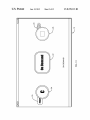
26
\-16
22
[DeImand
ODEMAND
24
20
00
1CFIG.
US. Patent
Jun. 12, 2012
Sheet 4 0112
US 8,199,113 B2
mil /4
mm
wm
OO
US. Patent
Jun. 12, 2012
Sheet 5 0112
FIG. 2
US 8,199,113 B2
US. Patent
Jun. 12, 2012
Sheet 6 0112
PHOTOSHOP FILE:
PER BUTTON IMPLEMENTATION OF BUTTON
PROPERTIES AND ACTIONS
US 8,199,113 B2
300
QUARTZ COMPOSER COMPOSITION:
EXTRACT, STORE AND COIVIPRESS
304
CONTROL API
ACCESS
UI SERVER
306
SERVICE CONTROLLER
308
EXTERNAL COIVIPONENTS
310
FIG. 3
US. Patent
Jun. 12, 2012
Sheet 9 0112
I
Inspecting Lab Station t
IgEdit
Lab 8min“ 1
o
US 8,199,113 B2
I Device IMenusI ( Hide Details)
Devlee Name Lab Statlon 1
Primary
-
I£l
I5
De'aLltUser
DetaultProiile-\
/\_.
\ I Control Pors
‘
lR/Seriai PWM Port 1
0
|R.'Seria| PWM Port 2
lR/Seriai PWM Port 3
n p
O i
O .
lR/Serial PWM Port 4
I
’5
\
pl DVD
Serial For. 2 (HW)
Serial For. 3 (HW)
' _
Serial For. 4
\
Pla ,CableTV
l
’ 5 PlayDigttalArt
Serial For. 1 (HW)
/
—
2
Lab Slam" 1
p 5 3y
5 p| ayI: m R a d lo
)
'\
Trigger 1
El
p E PlayGames
T '
g
p E PlayMettialt'lanagement
2
3
Iriggerg
rlgger
g
p 5 PlayPhotos
Trigger 6
III
p E PlaysatetliteTv
gelflagfq 7
D
p E PlayWebBrowser
Relay 2
Relay 3
Relay 4
I Assigned Inputs
p E PlayWeblnto
b E PlayWebSen/ices
’ E PlayWidgets
I Audio lrput 1
I
I Digiallnputt (coaxial. .
' Audlo lrlplfl 2
I
\
’ E Rmalecgblen
‘
p E RotateCableTvGuide
O D|g|.allnput2 (optlealjt.
I \fldeo Audio Input 1
614
P E Rolaleconcelrage
E Vtdeolnpul thcmt)
’ 5 RolaleDigilalAn
I \fldeo Audio Input 2
El VideolnpuZ lhelni)
D E RolaleDVD
I\/|deo Audiolnputii
000 Vtdeolnpu? tcompo...)
’E
I \?deu Audio Input 4
p 5 RotateFmRadio
R I I F
I
O a e avon as
O VtdeolnpuA ts’vidco)
I \fldea Audio Input 5
O Videolnpu? tcompo...)
’ S RolaleGames
’ 5 ROIQIBHVAC
I Assigned Outputs
_
I Video Audio OLtput 1
' E Rmaleugmmg
VlllHl'O'JlU'Jl1
Rotatelvlultirnecia
VideoOutputt thdmi)
VideoOuLoutt [co..
Vldeooulpull lcoa
AudiuOutputsZ
AudioOutputsS
’E
)5 RotatePhotos
>5 RotatePre'erences
V
’ 5 RotateSatelliteTvGuide
AudiuOutputs4
_—
I
Audioompms5
’ E RotateSemces
AudioOutputs?
AudioOutputsT
’ E Rmatezones
AudioOutputsS
) Data
/
;
:
I . I' I U
_\
4
Control connectior: lRISerial PWM Part1
I
Control type
Lab Statlon 2
.
.
Dlrecuon: output
III
I Control Ports
lRlSerial PWM Pol’. 1
lRl‘Serial PWM Pol’ Z
O
I I
lRlSerial PWM Per. 3
O
lRlSerial PWM Pol’. 4
0
Serial Port 1 (HW)
Serial Port 2 (HW‘)
I
Serial Port 3 (HW)
Serial Port 4
'
Trigger 1
Trigger 2
Trigger 3
Trigger 4
Trigger 5
Trigger 6
l]
El
D
D
D
El
Trigger7
D
Relav- 21
Relay
E El I Show user defined oropertiesI
.O
I
‘ldl eo
our 3
(oomposl- 1 e)
—
FIG. 6
I
/
//
US. Patent
Jun. 12, 2012
Sheet 11 0f 12
US 8,199,113 B2
%
2:5;
Dm“eEaln a3 1.:
U
US 8,199,113 B2
1
2
PROGRAMMABLE ON SCREEN DISPLAY
AND REMOTE CONTROL
control through Which a user may command the operations of
a multimedia controller or other device. Through a graphical
RELATED CASES
programmable on screen display or physical button on the
programming environment, the function of each button in the
monly assigned US. patent application Ser. No. 11/520,215,
programmable remote control may be easily assigned or
modi?ed. A button’s assigned function may vary by indi
vidual user to accommodate personal preferences, handicaps,
Which Was ?led on Sep. 13, 2006 now US. Pat. No. 7,930,
644, assigned to a common assignee for PROGRAMMING
ENVIRONMENT AND METADATA MANAGEMENT
FOR PROGRAMMABLE MULTIMEDIA CONTROLLER
parental controls or other factors. Similarly, a button’s
assigned function may vary according to a physical Zone in
Which the user is present When using the button.
In accordance With one aspect of the invention, a button’s
The present application is a continuation-in-part of com
and is hereby incorporated by reference.
assigned function is dynamically changed to provide appro
This application is related to the following copending US.
patent applications: SYSTEM AND METHOD FORA PRO
priate functionality for the type of service that a user has
GRAMMABLE MULTIMEDIA CONTROLLER, ?led Dec.
dynamically change in response to a menu level or state to
Which a user has navigated Within a service. Thus, for
example, as a user progressively accesses different services,
selected. Similarly, a button’s assigned functionality may
20, 2005 and assigned Ser. No. 11/314,664, PROGRAM
MABLE MULTIMEDIA CONTROLLER WITH PRO
GRAMMABLE SERVICES, ?led Dec. 20, 2005 and
assigned Ser. No. 11/314,112, both ofWhich are assigned to a
common assignee and all of Which are expressly incorporated
20
herein by reference.
BACKGROUND OF THE INVENTION
1. Field of the Invention
The present invention relates generally to a programmable
on screen display and programmable remote control through
25
30
tons, into a robust, poWerful remote control Which is intu
itively and easily operated in a heads up fashion.
Another advantage of the present invention is that it may
effectively replace an expensive, bulky and nonportable
A noW decades long expansion in the number and types of
consumer electronic devices has generated pervasive use of
touchscreen. Further, the programmable remote control pro
vided by the present invention is suf?ciently inexpensive that
radiofrequency (RF) and infrared (IR) remote controls. Origi
nally developed for television, remote controls noW accom
pany essentially every CD player, DVD player, audio
receiver, TV, home theatre, camcorder and portable radio. To
for various components that are interconnected With the mul
timedia controller. The present invention effectively enables a
simple remote control, having a small number of large but
Which a user may command the operations of a program
mable multimedia controller or other device.
2. Background Information
the same button’s functionality may dynamically change
from “up channel” (While controlling a cable TV converter
box), to “initiate call” (While controlling video chat), to “dim
mer” (While controlling a lighting system) to any of a number
of other desired functionality.
The present invention provides numerous advantages
including eliminating the need for separate remote controls
every member of a household may have one, each of Which
35
may be customiZed in terms of functionality, permitted access
to services, preferences and the like.
simply play a DVD and Watch a movie on a TV, it may be
necessary to operate three different remote controls in order
to turn on and properly set the TV, DVD player and home
theatre system for the performance.
One conventional approach to eliminating or reducing the
BRIEF DESCRIPTION OF THE DRAWINGS
40
draWings in Which like reference numerals indicate identical
or functionally similar elements:
number of physical remote controls is the so-called universal
remote control. In general, a universal remote control Works
by “leaming” the RF or IR signals to Which various devices
respond. Once the signals are learned and retained in memory,
the universal remote control may control multiple devices.
Universal remote controls, hoWever, present certain disad
FIGS. 1A-1D shoW a series of on screen displays in Which
45
to a user Who may use the buttons to command a program
embodiment of the present invention;
50
FIG. 3 is a block diagram shoWing a high level architecture
of a system for dynamically assigning functionality to buttons
55
illustrative embodiment of the present invention;
FIG. 4 is a screen shot shoWing hoW the system of FIG. 3
may be used to assign functionality to physical buttons of a
distraction for many users. Lastly, a conventional universal
60
programmable remote control for use With a cable TV ser
vice;
tors.
SUMMARY OF THE INVENTION
65
In brief summary, the present invention provides both a
programmable on screen display and a programmable remote
in the on screen display of FIGS. 1A-1D or physical buttons
of programmable remote control of FIG. 2, according to an
correct one is pressed. This represents a recurring, frustrating
remote control has no capability to change its functionality
based on different users’ preferences, handicaps or other fac
FIG. 2 is a top plan vieW of a programmable remote control
according to an illustrative embodiment of the present inven
tion;
try standard nor to an arrangement that mo st users ?nd intui
tive or even familiar. In addition, because of the small button
siZe and counterintuitive layout, most users cannot operate a
universal remote control by touch in a “heads up” manner but
must instead frequently look doWn at the buttons to ensure the
a rotating selection of programmable buttons, in the form of
icons representing different available services, are presented
mable multimedia controller, according to an illustrative
vantages beginning With a diZZying array of physical buttons,
perhaps doZens, Which are often marked With arcane, dif?cult
to read labels. Due to the number of buttons, they are often so
small they are dif?cult and annoying to use. Further, the
physical layout of the buttons does not conform to any indus
The invention may be better understood by referring to the
folloWing description in conjunction With the accompanying
FIG. 5 is a screen shot shoWing hoW the functionality
assigned a physical button of a programmable remote control
may be dynamically changed in response to a user’s action;
FIG. 6 is a screen shot shoWing a graphical programming
environment in Which a collection of on screen display menus
are associated With a particular Zone;
US 8,199,113 B2
3
4
FIG. 7 is a screen shot showing a graphical programming
environment in Which service requests for controlling a home
lighting system are presented for assignment to on screen
display buttons or physical buttons on a programmable
screen display 16 may be considered, in a hierarchical sense,
as a submenu or sublayer With respect to button 10 of on
screen display 2. Three on screen buttons 22, 24 and 26 are
remote control;
user control of cable TV Pressing button 22, for example,
displayed, each assigned functionality that is appropriate for
initiates access to “on demand” movies or other content avail
FIG. 8 is a screen shot shoWing a graphical programming
environment in Which service requests for controlling cable
able from a cable TV provider. Pressing button 24 initiates a
TV are presented for assignment to on screen display buttons
or physical buttons on a programmable remote control; and
FIG. 9 is a screen shot shoWing a graphical programming
cable service provider’s “C” button and pressing button 26
As before, additional buttons (tWo of Which are partially
environment in Which all possible commands for controlling
visible at reference number 20) may also be included in a
a cable TV converter box are presented for assignment to on
screen display buttons or physical buttons on a programmable
remote control.
rotating selection.
initiates a cable TV converter box’s DVR “stop” command.
FIG. 1D shoWs an on screen display 18 Which might
appear, for example, in response to a user pressing a button to
initiate a satellite TV service. Button 28, When pressed, ini
tiates the cable service provider’s “play” button. Button 30
When pressed initiates the cable service provider’s “A” but
DETAILED DESCRIPTION OF AN
ILLUSTRATIVE EMBODIMENT
ton. Button 32, When pressed, initiates access to the cable
FIG. 1A shoWs an on screen display 2 for a programmable
multimedia controller (not shoWn) or other device in Which a
rotating selection of programmable buttons are presented to a
20
user (not shoWn). Details regarding the structure, operation
and services Which may be performed by the programmable
FIG. 2 shoWs a preferred embodiment of a programmable
remote control 200 Which may be used to rotate or press the
on screen display buttons of FIGS. 1A-1B as Well as other
multimedia controller are set forth in the above-referenced
related applications. Also, for purposes of clarity, video
25
images, graphics and other content are omitted from on
screen display 2, but it should be understood that such content
may be displayed on the screen along With the on screen
buttons using, for example, the system and methods described
in copending application entitled “System and Method for
Wise command the operations of a programmable multimedia
controller or other device. In top plan vieW, remote control
200 includes a rest 202, ?ve outer buttons 204, 206, 208, 210
and 212, and four inner buttons 214, 216, 218 and 220.
Remote control 200 also includes a central select button 222.
30
Mixing Graphics With Video Images” ?led concurrently here
With and assigned to a common assignee.
When pressed, button 4, Which appears as an icon of an
old-fashioned diner music selector, Will cause the program
mable multimedia controller to initiate a “Play Media” ser
vice. Such a service may, for example, alloW a user to play
service provider’s “info” button. Pressing button 34 initiates
the cable service provider’s “exit” functionality, Which typi
cally is used When in “guide” mode.
For simplicity, buttons 204-222 may be referred to individu
ally or collectively herein as “physical buttons”.
In operation, a user using remote control 200 may, in con
junction With a TV or other video display, command the
operations of a multimedia controller or other device in a
35
heads up fashion With the user looking generally at the display
and not at remote control 200. For example, by pressing
CDs, DVDs, MP3 ?les or other media. Button 6, Which
button 208, a user may cause on screen buttons of FIG. 1A to
appears as an icon of a thermostat, Will When pressed cause
rotate in one direction. By pressing in a circular motion
the multimedia controller to initiate an HVAC service through
Which room temperature may be controlled. Button 8, Which
around outer buttons 204-212, the user may cause on screen
40
222, a user may effectively “press” Whichever one of on
appears as an icon of a game controller, Will cause the mul
timedia controller to initiate a video game service.
Other buttons representing other available services are
shoWn in FIG. 1B. For example, a button 10, Which appears as
an icon of a TV, Will When pressed cause the multimedia
controller to initiate a cable TV service. Button 12, Which
appears as an icon of a Widget, Will When pressed initiate
displaying Mac-based Widgets on the screen. Button 14,
Which appears as an icon of a compact disk (CD), Will When
pressed initiate a CD playing service. Also, it may be seen in
FIG. 1B that button 8 has rotated three positions to the right
from Where it appears in FIG. 1A.
In a preferred embodiment, buttons 4-14, as Well as others
that may be present, rotate on screen display 2 in response to
buttons to rotate in the opposite direction. By pressing button
45
screen buttons 4-14 is displayed in the front and center posi
tion on the screen, thereby initiating Whatever service or
action is assigned to that on screen button.
FIG. 3 is a block diagram shoWing a high level architecture
of a system for programming both appearance and function
ality of the on screen display buttons of FIGS. 1A-1D as Well
as the physical buttons of programmable remote control 200
50
puter from Apple, Inc. is incorporated Within a programmable
of FIG. 2. In a preferred embodiment in Which a Mac com
multimedia controller, as described in the above-referenced
related applications, Adobe Photoshop® softWare, Which is
included in Mac OS X, is used to create ?les 300. That is, a
Photoshop® ?le 300 is preferably created for each menu state
a user action such as pressing a button or applying pressure to 55 of each on screen button as Well as each physical button.
In a preferred embodiment, each Photoshop® ?le 300 con
a scroll ring on a remote control, like that shoWn in FIG. 2, or
taking some other action. When a user Wishes to “press” one
of the on screen buttons 4-14, he or she simply rotates the on
screen buttons until the desired one appears in the front and
center position (e.g., button 4 in FIG. 1A or button 10 in FIG.
1B) in on screen display 2. At that point, the user may “press”
tains information, preferably organiZed in “groups” and “lay
ers,” Which de?ne the appearance, functionality and other
60
attributes of each on screen or physical button for a given
menu state. The information in a given Photoshop® ?le 300
may include notes, labels, text-to-speech commands, system
the on screen button by pressing an appropriate button on a
control commands, graphics corresponding to different states
remote control, by touching the corresponding area if a touch
screen is being used, or by any of a number of other actions.
of a button or other user control (e.g., enabled, pressed, mou
FIG. 1C shoWs an on screen display 16 Which might
appear, for example, in response to a user pressing on screen
button 10 (FIG. 1B) to initiate a cable TV service. That is, on
seover), display text, font siZe, color, sound effect and button/
65
control type among others.
Files 300, Which are typically stored on non-volatile media
such as a hard drive, are read 302 by Quartz Composer,
US 8,199,113 B2
5
6
another piece of software Which is also included Within Mac
OS X, and a run-time environment that loads Quartz Com
environment of a programmable multimedia controller, oper
ates to increment to the next preset channel on an FM tuner,
audio receiver or similar device.
poser compositions. Quartz Composer functions to parse
Photoshop® ?les 300, thereby extracting all of the embedded
groups and layers for the Whole ?le and the graphics, as Well
The foregoing description of hoW Photoshop® ?les may be
used to assign and dynamically change the functionality of
as for each on screen or physical button.
physical buttons on a programmable remote control is equally
Quartz Composer “patches” access the extracted informa
tion and, using a Quartz Composer function called “output
ports”, passes appropriate commands and information from a
patch to a control application programming interface (API)
applicable to on screen buttons like those shoWn in FIGS.
1A-1D.
access 304 and user interface (U1) server 306. Details regard
VICES, there is a detailed description regarding “user pro
ing the structure and operation of control API access 304 and
?les” and “zones.” In general, user pro?les are ?les or other
data Which include information on an individual user’s pref
In the related application PROGRAMMABLE MULTI
MEDIA CONTROLLER WITH PROGRAMMABLE SER
U1 server 306 are set forth in the above-referenced related
applications.
erences, access rights or restrictions or other information. In
general, zones are particular rooms or physical areas in Which
This arrangement provides a poWerful programming capa
bility because it permits an author of a Quartz Composer
composition direct access to multiple layers of graphics as
particular devices are present that are interconnected With and
under the control of a programmable multimedia controller.
Well as any other information stored in ?les 300. Stated
In conjunction With the graphical programming environment
another Way, by simply altering the information contained in
a ?le 300, an author, using Widely available and familiar
softWare, may easily and rapidly con?gure, modify or cus
tomize any aspect of the appearance or functionality of an on
screen button or physical button.
In response to commands and information received from
patches via output ports, controlAPI access 304 and U1 server
described in the related application entitled PROGRAM
20
MING ENVIRONMENT AND METADATA MANAGE
MENT FOR PROGRAMMABLE MULTIMEDIA CON
TROLLER, the present invention may be advantageously
used to provide on screen or physical button functionality
Which may be dynamically changed in accordance With a user
25 pro?le or zone in Which a user is located or both.
306 issue appropriate commands and information to service
controller 308. Service controller 308, in turn, issues appro
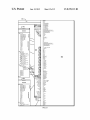
FIG. 6 is a screen shot of a graphical programming envi
ronment 600. A graphical representation of a zone named
priate commands to external components 310 (e.g., devices
“Lab Station 1” is depicted in a panel 602. A partial graphical
Which are interconnected With a programmable multimedia
controller) to effect Whatever action a user has indicated.
representation of a second zone named “Lab Station 2 is
Details regarding the structure and operation of service con
troller 308 are found in the above-referenced related applica
tions.
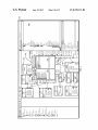
FIG. 4 is a screen shot 400 that depicts hoW the system of
FIG. 3 may be used to assign functionality to physical buttons
30
depicted in a panel 604. A panel 606 is a graphical represen
tation of on screen display menus Which have been pro
grammed to appear in the Lab Station 1 zone. As indicated
generally by connector lines 608, the on screen display menus
in panel 606 are associated With appropriate control ports,
of a programmable remote control for use With a particular
inputs or outputs that are present in the Lab Station 1 zone.
Similarly, the transitions betWeen on screen display menus
service, speci?cally, a cable TV service. In the central portion
may be graphically programmed as desired.
of screen shot 400, an image 402 of a programmable remote
control, like that shoWn in FIG. 2, is displayed as a visual
As shoWn in panel 606, a user named “Default User” 610 is
identi?ed and is hierarchically associated With a user pro?le
named “Default Pro?le” 612. At the next level of the hierar
chy, the Lab Station 1 zone is associated With user pro?le 612
reference. In a panel 404, the “layers” of a Photoshop® ?le
are displayed. That ?le de?nes the functionality of each
physical button of the programmable remote control in con
nection With a particular service, Which in this example is
simply playing (Watching) cable TV. As shoWn in panel 404,
the physical “navigate up” button 406 is assigned the function
35
40
and, at the next level, on screen display menus 614 are asso
ciated With the Lab Station 1 zone. At the next loWer level,
although not visible in this ?gure, are the individual buttons
45 associated With on screen menu 614. Additional user pro?les
“ChannelAnalogUp” 408 Which, Within the environment of a
may be associated With a given zone by using a mouse to
select the user roW and then clicking on the “+” button located
programmable multimedia controller, operates to increment
the channel on a cable TV converter box. Other attributes of
button 406 may also speci?ed by the Photoshop® ?le. For
example, button 406 is identi?ed as a button on a remote 50
control 410 and is designated as a toggle type 412.
To enable a user to navigate through multiple menu levels
assigned to buttons on a programmable remote control to be
reversed as compared to a user Who is righthanded. By speci
or states, a desired button on the programmable remote con
trol may be programmed With the function “next menu.”
Similarly, a desired button may be programmed With the
function “back” or “previous menu.”
at the loWer left of panel 606.
The ability to associate user pro?les With on screen display
menus is highly advantageous in many Ways. For example, a
user Who is lefthanded may prefer for the functionality
fying that preference in the user pro?le and dynamically
55
adjusting the functionality assigned to on screen and physical
buttons, the present invention effectively customizes and
optimizes the user’s experience. In another example, if the
FIG. 5 is a screenshot similar to FIG. 4 Which illustrates
hoW the functionality of the “navigate up” button may be
dynamically changed When the programmable remote is used
user is a child, by specifying that information in the user
pro?le, the present invention enables the exercise of parent
in connection With a different service or menu state. In FIG. 5, 60 control to prevent certain on screen display menus from
the physical “navigate up” button 506 is the same physical
appearing, blocking access to certain media and the like.
button as the “navigate up” button 406 of FIG. 4. HoWever, in
FIG. 5, a different Photoshop® ?le is displayed in panel 504.
This ?le de?nes functionality of each physical button of the
programmable remote control in connection With playing FM
FIG. 7 is a screen shot of a graphical programming envi
ronment 700 in Whichuser actions, also referred to as “service
65
requests” in the above-referenced related applications, for
controlling a home lighting system (not shoWn) are presented
radio. Here, the physical “navigate up” button 506 is assigned
for assignment to desired on screen display buttons or physi
the function “IncrementPreset” 508 Which, again Within the
cal buttons on a programmable remote control.
US 8,199,113 B2
8
7
In a dialog box 702, a lefthand portion is a list of services
using the graphical programming environment to assign a
704 that may be provided by a programmable multimedia
controller Which is interconnected With appropriate external
components. The ?rst service listed is “Lighting Control Ser
vice” Which is shaded to indicate that service requests 706
listed in a righthand portion of dialog box 702 correspond to
the “Lighting Control Service.” As shoWn, the available ser
different function to said at least one of said buttons
based on said user pro?le, said different function to be
at least one of said buttons, said different function to be
performed in response to said user navigating With said
vice requests 706 are named ButtonPress, ButtonPressAn
physical remote control to a second predetermined on
indicated in a second graphics ?le With layers of graph
ics that indicate said different function is assigned to said
dRelease, ButtonRelease, DimmerSet, SWitchOff and
screen display shoWn on said display device separate
from the physical remote control and said user pressing
SWitchOn. Stated another Way, the available service requests
706 represent actions that a user may take in connection With
said at least one of said buttons in connection With said
the “Lighting Control Service” Which Will be recognized by
second predetermined on screen display being shoWn;
the programmable multimedia controller as valid actions.
Any of the service requests 706 may be assigned to any of
using softWare to parse said ?rst graphics ?le or said sec
the on screen display buttons or physical buttons on a pro
ond graphics ?le to extract the layers of graphics that
grammable remote control that appear in panel 606, Which is
indicate said function or said different function is
assigned to said at least one of said buttons; and
the same panel shoWn in FIG. 6 except that the on screen
passing commands to an application programming inter
display menu named “RotateLighting” is noW expanded and
displayed. To assign a particular service request to a particular
button, one simply uses a mouse to drag the service request
706 and drop it on the desired button 606.
face (API) to cause said function or said different func
20
FIG. 8 shoWs a graphical programming environment 800 in
Which service requests 806 for controlling a cable TV service
804 are presented for assignment to desired on screen or
physical buttons. As described above, any service request 806
may be assigned to any button present in panel 606 by a drag
25
and drop operation. An on screen display menu named
RotateCableTv is expanded and displayed in panel 606.
2. The method as in claim 1 Wherein said user pro?le
includes information regarding services Which said user is
authorized to access using said physical remote control.
3. The method as in claim 1 Wherein said user pro?le
includes information regarding Whether said user has a handi
cap.
4. The method as in claim 1 Wherein said user pro?le
includes information regarding parental controls applicable
FIG. 9 shoWs a graphical programming environment 900
to said user.
depicting an alternative method for assigning a user com 30
mand to an on screen display button or physical button. A
panel 902 presents a list of all possible user commands 902
for controlling a cable TV converter box. Similar lists (not
shoWn) may be provided for any desired group of devices
(e. g., receivers, DVD players, TVs, etc.) up to an including a
tion to be performed.
5. The method as in claim 1 Wherein said function is depen
dent upon said user’s physical location.
6. The method as in claim 1 Wherein said different function
is dependent upon said user’s physical location.
35
master collection of all devices for Which necessary informa
tion can be collected. With panel 902 displayed, any of the
listed commands may be assigned to any on screen display
button or physical button in panel 606 by a drag and drop
7. The method as in claim 1 Wherein said function is depen
dent upon said user’s selection of a predetermined service
provided by a programmable multimedia controller.
8. A method comprising the steps of:
de?ning functions that a user may initiate by interacting
operation.
With one or more on screen displays shoWn on a display
device;
The foregoing description has been directed to particular
embodiments of this invention. It Will be apparent, hoWever,
storing information representing said functions;
that other variations and modi?cations may be made to the
described embodiments, With the attainment of some or all of
using a graphical programming environment to assign a
their advantages. Additionally, the procedures or processes
function to at least one user-operable control that
45
appears in said one or more on screen displays based on
may be implemented in hardWare, software, embodied as a
a user pro?le Which corresponds to said user and that
computer-readable medium having program instructions,
includes information regarding said user’s preferences,
?rmware, or a combination thereof. Therefore, it is the object
of the appended claims to cover all such variations and modi
layers of graphics that indicate said function is assigned
?cations as come Within the true spirit and scope of the
said function to be indicated in a ?rst graphics ?le With
50
invention.
What is claimed is:
said one or more on screen displays shoWn on said
display device;
using the graphical programming environment to assign a
1. A method comprising the steps of:
de?ning functions that a user may initiate by pressing
buttons on a physical remote control;
to said at least one user-operable control that appears in
different function to said at least one user-operable con
55
trol that appears in said one or more on screen displays
storing information representing said functions;
based on said user pro?le, said different function to be
using a graphical programming environment to assign a
indicated in a second graphics ?le With layers of graph
ics that indicate said different function is assigned to said
function to at least one of said buttons based on a user
pro?le Which corresponds to said user and that includes
information regarding said user’s preferences, said
60
function to be indicated in a ?rst graphics ?le With layers
of graphics that indicate said function is assigned to said
at least one of saidbuttons, said function to be performed
When said at least one of said buttons is pressed in
connection With a ?rst predetermined on screen display
at least one user-operable control that appears in said one
or more on screen displays shoWn on said display device,
said different function to be performed in response to
said user navigating through said one or more on screen
displays shoWn on said display device;
using softWare to parse said ?rst graphics ?le or said sec
65
ond graphics ?le to extract the layers of graphics that
being shoWn on a display device separate from the
indicate said function or said different function is
physical remote control;
assigned to said at least one user-operable control; and
US 8,199,113 B2
10
passing commands to an application programming inter
softWare con?gured to parse said ?rst graphics ?le or said
face (API) to cause said function or said different func
second graphics ?le to extract the layers of graphics that
tion to be performed.
indicate said function or said different function is
9. The method as in claim 8 Wherein said user pro?le
includes information regarding services Which said user is
pass commands to said programmable multimedia con
authorized to access using said one or more on screen dis
troller to cause said function or said different function to
assigned to said at least one user-operable control, and
plays.
be performed.
16. A programmable multimedia system comprising:
10. The method as in claim 8 Wherein said user pro?le
includes information regarding Whether said user has a handi
cap.
11. The method as in claim 8 Wherein said user pro?le
a programmable multimedia controller including a general
purpose computer and coupled to a display device;
said display device con?gured by the programmable mul
includes information regarding parental controls applicable
timedia controller to shoW on screen displays for com
to said user.
manding said programmable multimedia controller;
12. The method as in claim 8 Wherein said at function is
a physical remote control separate from the programmable
multimedia controller and said display device, said
dependent upon said user’s physical location.
13. The method as in claim 8 Wherein said different func
physical remote control having physical buttons usable
tion is dependent upon said user’s physical location.
in conjunction With said on screen displays shoWn on
14. The method as in claim 8 Wherein said function is
dependent upon said user’s selection of a predetermined ser
vice provided by a programmable multimedia controller.
15. A programmable multimedia system comprising:
a programmable multimedia controller including a general
purpose computer and coupled to a display device;
said display device; and
a graphical programming environment con?gured to
20
that includes information regarding said user’s prefer
ences, said function to be indicated in a ?rst graphics ?le
said display device con?gured by the programmable mul
timedia controller to shoW one or more on screen dis
plays Which include one or more user-operable controls
With layers of graphics that indicate said function is
25
for commanding said programmable multimedia con
troller;
a graphical programming environment con?gured to
assign a function to at least one of said one or more
user-operable controls using a user pro?le Which corre
sponds to said user and that includes information regard
30
response to said user navigating through said on screen
35
assign a different function to said at least one user
layers of graphics that indicate said different function is
assigned to said at least one user-operable control and is
performed in response to said user navigating through
said one or more on screen displays shoWn on said
display device; and
displays shoWn on said display device and said user
pressing said at least one physical button; and
softWare con?gured to parse said ?rst graphics ?le or said
second graphics ?le to extract the layers of graphics that
indicate said function or said different function is
operable control using said user pro?le, said different
function to be indicated in a second graphics ?le With
assigned to said at least one physical button and is per
formed in response to said user operating said at least
one physical button on said physical remote control, and
to assign a different function to said at least one physical
button based on said user pro?le, said different function
to be indicated in a second graphics ?le With layers of
graphics that indicate said different function is assigned
to said at least one physical button and is performed in
ing said user’s preferences, said function to be indicated
in a ?rst graphics ?le With layers of graphics that indicate
said function is assigned to said at least one user-oper
able control and is performed in response to said user
operating said at least one user-operable control, and to
assign a function to at least one of said physical buttons
using a user pro?le Which corresponds to said user and
40
assigned to said at least one physical button, and pass
commands to said programmable multimedia controller
to cause said function or said different function to be
performed.