1
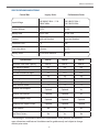
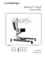
Alliance™ Stand
Assist Lifts
!"#$%&'())*)#'+,-,')./0%
!"#$%&'
Legacy Series
Performance Series
!"#$%&%'##%()
!"*!%&%+##%()
!"#,%&%$##%()
!"**-!"*.%&%'##%()
!"*#-!"."%&%+##%()
!"./-!".,%&%$##%()
Operator
Instructions
Alliance Stand Assist
Thank you for choosing Chattanooga Alliance Patient Lift!
01%)23324%52462%718-%9(2:52%42;14<%3=2%>1((1?@AB%@A>14C:3@1AD
Dealer Name: ____________________________________
Telephone: ______________________________________
Serial #: _________________________________________
Date of Purchase: _________________________________
INSPECT YOUR MERCHANDISE
Upon receipt of your Patient Lift, verify that all merchandise is complete and free from any
shipping damage.
Refuse delivery if the packaging appears to be badly damaged. If the merchandise is received damaged or is missing components, contact the shipping company immediately and
file a claim.
For further assistance, contact your local dealer or Product Support at the following:
1-800-494-3395 USA
[email protected]
DJO, Inc.
1430 Decision Street
Vista, CA 92081 USA
T: 1-800592-7329 USA
DJOGlobal.com
© 2013 DJO, LLC. All rights reserved.
2
Alliance Stand Assist
SAFETY
The Stand Assist sit-to-stand patient lift allows a caregiver to lift and transfer a patient safely
with minimum physical effort.
Before attempting to lift anyone, you should practice operating the lift and be able to explain
to the patient the lifting and transfer procedures.
Always keep the Operator’s Instructions Manual available with the lift.
SAFETY INSTRUCTIONS
• Special care must be taken with patients who are comatose, spastic, agitated, or otherwise
severely handicapped. A competent caregiver must always be present during any patient
lifting.
• The sole function of the patient lift is for transferring a patient from one utility (beds,
bathtubs, toilets, etc.) to another.
• The lift should not be used to transport or move patients from room to room or over
longer distances. Transfers should normally take place within the same patient room or
bathroom.
• Do not put anything (e.g. cushion, pad, etc.) between the user and the sling. This may
cause user to slide out of the sling and cause injury.
• The user/patient being transferred should be positioned in the center of the area being
transferred from (i.e. bed, wheel chair, chair, commode, etc.) before being lifted, as well as
when he/she is returned.
• Keep lifter base widened (use foot pedals to accomplish this) and brakes unlocked during
lifting. If the brakes are locked during the lift process, the lift may become unstable.
• While the patient is suspended, always keep the patients centered between the base
legs.
• Do not attempt to roll the lift or casters over floor obstacles while the user is in the sling
and on board.
• Use only Chattanooga slings (manufactured by BestCare) specially designed and tested
for Chattanooga patient lifts . Do not use slings manufactured by other companies on
Chattanooga Stand Assist sit-to-stand patient lift. Chattanooga is not responsible for any
consequence resulting from using non-Chattanooga products.
• Use only Chattanooga or approved Chattanooga parts and components. Chattanooga is
not responsible for any adverse consequence resulting from using parts and components
from other manufacturers.
• Service and repair of the patient lift should be performed by Chattanooga or its authorized
dealers ONLY. Chattanooga is not responsible for any consequence resulting from any
unauthorized service or repair.
• Never attempt to lift over the maximum capacity of the lift and any accessories used
in conjunction with the lift. The maximum safe working load for the lift will be clearly
labeled on the lift.
3
Alliance Stand Assist
DEFINITIONS AND SYMBOLS
In this manual the user refers to the patient or resident and may be used interchangeably at
different times. Caregiver refers to the operator or person who is assisting with the transfer.
Symbols used in this manual and their meanings:
Warning! Failure to heed this warning may result in damage to the product or
serious injury to the operator and/or user.
Important instructions follow. Read and understand the instructions in the
manual before using the product.
NOTE: Important information concerning the product and/or its correct and
proper usage follows.
4
Alliance Stand Assist
PRODUCT FEATURES
DESCRIPTION & APPLICATIONS
Chattanooga presents the Stand Assist Series of sit-to-stand patient lifts, a solution for
patient transfers between bed, chair or commode. The lift reduces injury risk associated with
antiquated manual patient lifting practices. Competitively priced and combined with a unique
design, the lift provides a new level of comfort and safety. The Stand Assist lift has set the
standard for value and is an option for residential use.
•
•
•
•
•
•
•
•
400, 500, 600 Lb. safe working loads
Low base
Fully adjustable knee pad
Removable foot platform
Four sizes of deluxe padded slings
Optional buttock support strap
Knee pad strap for extra leg support
Features alternative Sani-sling hook-up that eliminates underarm
transfer.
5
discomfort during
Alliance Stand Assist
SPECIFICATIONS AND OPTIONS
Control Box
Legacy-Series
Performance-Series
Input Voltage
220-240VAC 50Hz / 110120VAC 60Hz
220-240VAC 50Hz /
110-120VAC 60Hz
Output Voltage
24 VDC
24 VDC
Battery Pack
24 VDC 5AH
24 VDC 5AH
Control
Panel and Handset
Panel and Handset
Protection Class
N/A
IP66
Over-duty alarm
by buzzer
by LCD
Battery Status
by LED color indicator
by LCD
Specifications
400 Lb.
500 Lb.
600 Lb.
400 Lb.
68”
33”
26”
38”
500 Lb.
68”
33”
25.5”
38”
600 Lb.
68”
33”
25.5”
38”
Base height clearance
4.5”
4.5”
4.5”
Overall length
Boom Internal Width
40”
19”
40”
19”
40”
19”
Bariatric Size Kneepad
Optional
Optional
Yes
Bariatric Size Footrest
Optional
Optional
Yes
Buttock Support Strap
Optional
Optional
Optional
Kneepad/Calf Support Strap
Optional
Optional
Optional
Quick Release
No
Yes
Yes
Dual Front Casters
No
Yes
No
Maximum Safe Load Capacity
Max. height of Boom
Min. height of Boom
Base closed external width
Base open external width
*Chattanooga is committed to continuous improvements of our products, therefore the
specs, dimensions and features listed above are for guidance only and subject to change
without prior notice.
6
Alliance Stand Assist
ASSEMBLY
Prior to assembly, unpack all parts from the shipping carton and check for any missing
parts. Contact your dealer immediately if a part is missing.
Parts List for
PERFORMANCE-Series
1.
2.
3.
4.
5.
6.
7
8
9.
10
Base
Mast
Control Box
Pendant
Actuator
Lifting Boom
Kneepad Assembly
Footrest
Castor with Brake
Front Castor
Parts List for
LEGACY-Series
1.
2.
3.
4.
5.
6.
7
8
9.
10
Base
Mast
Control Box
Pendant
Actuator
Lifting Boom
Kneepad Assembly
Footrest
Castor with Brake
Front Castor
7
Alliance Stand Assist
STEP BY STEP ASSEMBLY
()$*+,
Engage the brakes. Remove the bolts from the bottom of the mast and
base. Pull the Mast to an upright position. Re-insert the bolts into the
holes at bottom of the mast and tighten the nuts.
()$*+-
Attach boom to top of mast. Re-insert the bolts into the holes at bottom
of the mast and tighten the nuts.
8
Alliance Stand Assist
STEP BY STEP ASSEMBLY (CONT)
()$*+.
A. Attach the bottom of Actuator to the bracket on the Mast and insert pin.
Insert keeper ring through hole in pin to secure base of actuator.
B. Attach the top of the Actuator to the bracket on the Boom and insert pin.
Insert keeper ring through hole in pin to secure actuator to upper bracket.
!"
#"
9
Alliance Stand Assist
STEP BY STEP ASSEMBLY (CONT)
()$*+/
KNEEPAD ASSEMBLY FOR PERFORMANCE-Series
Insert slotted bolt
through bracket with
washer on the outside
and loosely attach
threaded knob to the
mast by turning the knob
two times.
Slide “L” arm inside bracket
with slotted bolt head
inside the “L” arm then
tighten to secure. Repeat
these steps for the other
side.
Kneepad
With both “L” arms
securely attached to the
mast, slide the kneepad
onto the “L” arms and
fasten into place with “U”
bracket and knob bolt.
“U” Bracket
Knob Bolt
Mast
L-Shape Arms
Threaded Knob
Bracket
10
Alliance Stand Assist
BATTERY INSTALLATION
FOR PERFORMANCE-Series
Install the control box. Slide the control box over and onto the flat metal hook mounted at
the bottom of the Mast. Line up the control box with the hole at the top of the mast and
insert the screw to hold the control box in place. Secure the control box by turning the lock
mechanism into the lock position.
CONTROL BOX
Plug-Ins for Performance-Series
LCD display / LCD
Lifting actuator UP
Lifting actuator DOWN
AC Power Plug
Battery pack release
Battery indicator
Actuator Plug
Emergency button
Pendant Plug
11
Alliance Stand Assist
CONTROL BOX FEATURES:
•
•
•
•
•
•
Smart charging function for longer battery life
Battery capacity indicator on battery pack
Soft start and stop for lifting actuator
Soft and Hardware over-current protection
Actuator’s Over-duty protection with sign on LCD
Emergency stop button interrupts the power supply to the actuator and makes the actuator stop
immediately in case of sudden danger
• Internal charger
• LCD-display showing battery capacity and indication when the battery needs recharging.
• Audible alarm for low battery capacity
• Standard protection class: IP 66
• Pulling-proof design to lock the AC plug
LCD INDICATORS:
Overload
Capacity
Function
90%
Battery is charged to
around 90%
70%
Battery is charged to
around 70
Battery Volume
Overused
50%
low battery
Battery Low (Blink)
12
50% Battery
Capacity Remaining
Charge batteries
immediately.
25%
25% Battery
Capacity Remaining
Charge batteries
immediately.
10%
Battery is charged to
around 10%
Buzzer beeps / Only
lowering possible
0%
Power off
Alliance Stand Assist
CONTROL BOX FEATURES (CONT)
EMERGENCY STOP FOR PERFORMANCE ELECTRONICS ONLY
Emergency stop button interrupts the power supply to the actuators and makes the
actuators stop immediately in case of sudden danger.
Press RED button
Turn RED button clockwise
EFGHIJ
KLEFGHIJ
*It is strongly recommended that the utton in pressed own when the lift will not be used
for over 3 days to maintain optimal battery life and performance.
FEATURES OF POWER PLUG:
C-CLAMP :
• when the battery is being charged, insert this C-clamp to secure the power plug
WATERPROOF COVER:
• when control is not being used, the cover should be closed to prevent water ingress.
G&;(:C9
O:3249411>%;1624
REMOVE AND INSERT BATTERY PACK:
REMOVE : press button A and pull out in the up direction (Fig.1)
INSERT:%
• put
% the battery pack all the way down to position as shown in Fig.2
• slide into direction C while having the release button pressed (Fig.3)
• make sure the battery pack won’t slide back off by pulling the battery pack
without pressing the release button B.
M@BN!
M@BN.
M@BN*
13
Alliance Stand Assist
BATTERY ASSEMBLY FOR LEGACY - SERIES
Attach the Control Box Hanging Bracket to the Mast and tighten the nuts. Once the
bracket is secure, then place the Legacy Electronic Box inside.
CONTROL BOX INSTRUCTIONS FOR LEGACY - SERIES
Battery Indicator
Battery Test Button
Emergency Button
14
Alliance Stand Assist
WORKING WITH THE BATTERY
Charger Plug
Pendant Plug
Actuator Plug
CHECKING THE BATTERY:
• Check batteries by pressing the Battery Testing Button (blue circle with a battery
sign) on the control box.
• Batteries are fully charged when all lights on the Battery Indicator are “ON”.
• Charge batteries when Indicator shown only one “GREEN” light.
• Do not use the lift when no “GREEN” light is shown. Charge the batteries
immediately.
• Replace batteries when frequent charging is needed.
CHARGING THE BATTERY
•
•
•
•
•
•
•
Ensure the power is switched “ON” (the red “RESET” button should be up).
Insert charging plug into charging port on the control box.
Plug charger to power supply.
All lights of battery indicator should be “ON” while charging.
It takes approximately 2-3 hours to fully charge the batteries from one green light.
It takes approximately 7-9 hours to fully charge the batteries from the red light.
Do not leave the batteries on charging for an extensive period of time. This will
shorten the life of the batteries.
• Do not let the batteries run down to the last red light. This might shorten the life of
the batteries or damage the batteries.
• Unplug the charger first before using the lift.
15
Alliance Stand Assist
WORKING WITH THE BATTERY (CONT)
KNOW WHAT YOUR BATTERY IS TELLING YOU
!"#!
!"#$%!
!"##$!
!"##$!
!"##$!
!
!"!
!"!
!"!
!"!
!"!
!"##$%&'()*+,!
!"!
!"!
!"!
!"!
!"#$!!!!! !""!
!""!
!""!
!""!
!""!
!""#$%&'()"!
!"#$%&'())&*(#+&,-.''*/01+'2!"#$%"#&'($!
!""!
!""!
!""!
!""!
!"#$!"%%&'(&)$*'$!"#$+*,,&+%(*,!
!""!
!
WARNING BUZZERS
The control box has a buzzer that provides you with information on the status of the
batteries and the lift. To stop the buzzer, push down the RESET button or press the
Battery Test button.
!"##$%&'()$! !"#!$%&!'"!
!"#$!
!!!""#$%$"&!
!"#$%&'(#))&$*&+'*,,&-*#)&./0!
!!!""#$%$"&!
!!!""#$%$"&!
!!!""#$%"&"'(%
!"#$%&'$(!)*&!
!!!"#$%&''()!
!"#$%&''()*!
!"#$%&'(#")*+,-./)012!
!"#$%&''()*!
!"#$%&'()*%+,-!
"#$%!&'(!)*++#$%!
!"#$%&'()$#"*!
!"#$!"%%&'(!
!"#$%&'()$#"*!
!"#$%&'(#()**+',,#$-#.*'$#*/0'$1#(*23,*%-4,*
!"#$%&"'%()*'+!
!"#$%&'(#))&$*&+'*,,&-*#)&./0!
!"#$%&'(#))&$*&+'*,,&!"#$%&'(!
!"#$%&"'(%))"*+",-!
!"#$$%$%&'(")'*'&+,(%&#(-(#)./0!
IMPORTANT NOTES ON CHARGING
• Push lift to charging location and charge the batteries with the charger provided.
Avoid unplug hand control and motor from control box. Frequent plug/unplug of
the hand control and motor into/from the control box may damage the control box.
• Do not charge batteries over 12 hours.
Patient Lift will not operate while charging.
16
Alliance Stand Assist
OPERATING INSTRUCTIONS
Double check all assemblies for tightness and read operating instructions carefully
prior to use.
Do not attempt to use patient lift unless the patient exhibits control over the upper
body, strength to grasp the handles, ability to bear some weight and flexibility in
knees, hips and ankles.
PREPARATION BEFORE LIFTING
• Turn on the power by twisting the RED RESET BUTTON clockwise
• Press the UP or DOWN button on the hand control once and check if the
battery indicator lights are on.
• Position the base of the lift around or under the object
• Widen the base and engage the caster brakes
Do not attempt to transfer a patient without prior approval of the person’s nurse.
Also, do not transfer without having studied the instructions and performed
several practices in operating the product.
Together with the patient’s doctor, nurse or medical attendant, select a sling that
is both practical and comfortable. The sling selected should be one that serves
the needs of the patient, while providing the patient with optimal safety. Never
interfere with the lift unless instructed by the attendant.
Have a doctor, nurse, or medical attendant (experienced in the use of the Stand
Assist Lift) present during the first few times the lift is used to transfer a new user.
17
Alliance Stand Assist
FITTING STAND ASSIST SLING
•
•
•
•
Position the patient in a sitting position
Slide the sling down patient’s back to lumbar position.
Draw the shoulder straps to the front of the patient close to the chest.
Draw the waist belt around patient’s waist and press together to fasten.
Attach the shoulder straps to the hooks.
Shoulder strap loop
Shoulder strap
Velcro waist belt
Sling Loop Options
LONG LOOP
LONG LOOP - reclined position
CENTER LOOP - semi reclined
SHORT LOOP - most upright
CENTER LOOP
SHORT LOOP
OR
FOR SLING APPLICATION
• Place sling behind seated patient with the 2 red pads under the arms.
• Cross the adjustable chest belt over and fasten it securely using the buckle (adjust for
comfort).
• Cross the short black strap over and pull the left loop strap through the black strap.
• Hook the two loop straps to the hooks on the lift boom using the same hook and loop
sequence on each side.
• The black strap will be straight across in front of patient to stabilize the sling during lift.
• Have patient grasp handles on boom and tilt head back slightly.
• Make sure the patients feet are firmly on the platform and knees are touching the
kneepads with kneecaps just above the padding.
• Use the lift to complete the lift and pivot transfer.
18
Alliance Stand Assist
FITTING SUPPORT STRAP
DIAGRAM 1
P
Q
DIAGRAM 2
DIAGRAM 3
:
)
• Check sling weight capacity for the patient being lifted.
Do not exceed maximum safe working load.
• Review following procedures carefully prior to
attempting lift. Call with any questions.
• Position the sling around the buttocks of the patient.
This sling is designed to support the middle and lower
part of the body.
• Attach the sling strap to the lower “pig tail” “A” on the
mast of the Stand Assist lift as in Diagram 1. Bringing
the other side around the back of the patients’s
buttocks (to fit like a park swing) and attach lower “pig
tail” “B”.
• Position sling so it gives the greatest support to middle
and lower part of the patient being lifted.
• Notice, in Diagram 2 and 3, that the Buttock strap MUST
be used with the Stand Assist sling. These slings are
designed to compliment one another in providing the
greatest comfort and security for the patient being
transferred.
• Do not lock caster brakes to allow lift to properly
balance weight.
LIFTING HINTS
• Prior to beginning a lift have the patient lean slightly back and look at the a 45 degree
angle to the ceiling; this help position the sling; this is recommended only at the start of a
lift
• Try the sling straps in various color positions to establish best fit
• Always insure the same color straps on each side are attached to lift
• Should patients have a larger girth in mid section or back side area try the optional
buttock strap to help with initial lift leverage
• Remember this lift is designed for pivot transfers and it is not necessary to lift to full
upright position; as long as the patients body clears bed or chair and vice versa you can
It is not uncommon for the strap to loosen and drop down as lift proceeds.
19
Alliance Stand Assist
LIFT AND TRANSFER FROM BED
•
•
•
•
•
•
•
•
•
•
•
•
•
•
•
•
•
Fit sling as described in “Fitting Stand Assist Sling”.
Push lift towards patient. Open the base of the lift. Apply the brakes in both rear casters.
Position patient’s feet on the foot platform and knees against the knee pad.
Attached the sling straps to the hooks.
Have the patient’s hands holding the handles. For patients who cannot hold the handles,
have them hold their arms around the chest.
Press the “UP” button on the hand control.
Before the patient’s body has lifted from the bed, stop and make sure the sling is secured
and patient’s knees are against the knee pad.
The patient should be comfortable with the pressure under the arms. If not, adjust the
sling and try another loop option to release pressure.
Press the “UP” button until the patient’s body has completely left the bed.
Transfer to another object can be done at this position without the patient attending a full
standing position.
Release the brakes, close the base, and pull the lift away from the bed.
Lower the patient to the object intended.
To lift patient in a standing position, continue to lift until the patient’s knees are locked in a
standing position.
At the standing position, patient’s knees may move away from the knee pad.
Release the brakes, close the base, and pull the lift away from the bed.
Lower the patient to the object intended.
Reverse the above procedures when lowering the patient to the bed.
20
Alliance Stand Assist
LIFT AND TRANSFER FROM SEATED POSITION
• Fit sling as described in “Fitting Stand Assist Sling”.
• Push lift towards patient. Open the base of the lift to go around the chair. Apply the brakes
in both rear casters.
• Position patient’s feet on the foot platform and knees against the knee pad.
• Attached the sling straps to the hooks.
• Have the patient’s hands holding the handles. For patients who cannot hold the handles,
have them hold their arms around the chest.
• Press the “UP” button on the hand control.
• Before the patient’s body is lifted from the chair, stop and make sure the sling is secured
and patient’s knees are against the knee pad.
• The patient should be comfortable with the pressure under the arms. If not, adjust the
sling and try another loop option to release pressure.
• Press the “UP” button until the patient’s body has completely left the chair.
• Transfer to another object can be done at this position without the patient attending a full
standing position.
• Release the brakes, close the base, and pull the lift away from the chair.
• Lower the patient to the object intended.
• To lift patient in a standing position, continue to lift until the patient’s knees are locked in a
standing position.
• At the standing position, patient’s knees may move away from the knee pad.
• Release the brakes, close the base, and pull the lift away from the chair.
• Lower the patient to the object intended.
• Reverse the above procedures when lowering the patient to the chair.
21
Alliance Stand Assist
LIFT AND TRANSFER USING SANI SLING
SANI (TOILETING) SLING
The Toileting Sling can be used with the Stand Assist to lift a patient in a sitting position.
When in use the Stand Assist Toileting Sling supports the client under the thighs and across
the mid-back area.
R=18(<24%534:9%(119
R=18(<24%534:9
S2(;41%?:@53%)2(3
E2B%534:9
E2B%534:9%(119
The Sani (Toileting) Sling is not suitable for patients who have
involuntary movements or patients with limited postural control.
Fitting the Sani (Toileting) Sling
•
•
•
•
•
•
•
Slide the sling down patient’s back to lumbar position.
Draw shoulder straps under the arms and around the chest into the front.
Draw Velcro waist belt around waist and press together to fasten.
Draw each leg support under the thigh.
Crisscross leg straps by feeding one of the leg straps through the other strap.
Attach shoulder straps to hooks in upper ends of the lifting arms.
Attach leg straps to hooks in the lower ends of the lifting arm.
22
Alliance Stand Assist
MAINTENANCE AND INSPECTION
The operator of the lift shall inspect the Stand Assist Lift before each use.
•
•
•
•
Check all bolts for tightness.
Make sure the base can be easily widened and that all lift parts are in place.
Make sure that casters can be turned freely, and that caster brakes can be engaged.
Make certain all necessary items (i.e. slings, wheelchairs, etc.) are ready for use.
At least once a month, the lift should be thoroughly inspected by a person qualified to
recognize any signs of wear and tear and looseness of bolts or parts. Replace any worn parts
immediately.
To lubricate, put a drop of oil on the following points when the Stand Assist Lift is placed into
service and every month thereafter: Top of Mast, Spreader Hinge, and Caster Axles.
ITEM
BOOM & SPREADER BAR
Check connections between Boom and Mast
for improper connection, looseness or wear.
Check the Boom for bending and deflection.
MAST
Check the Mast for bending or deflection.
BASE & FOOT PEDAL
Check bolts and nuts for looseness..
Check casters and axle bolts for tightness.
Check rubber parts on the casters for defletion
FIRST
RECEIVED
MONTHLY
X
X
EVERY 3
MONTHS
X
23
X
X
X
X
X
X
X
X
Alliance Stand Assist
MAINTENANCE AND INSPECTION (CONT)
FIRST
RECEIVED
ITEM
MONTHLY
BASE & FOOT PEDAL
Apply grease to caster ball bearings if needed.
X
Check welding joints for rust and crack.
CLEANING
AS NEEDED
ACTUATOR & CONTROL BOX
Make sure the control box is firmly affixed to the
mast.
Make sure the actuator is secured to the Boom
and mast with pins and key rings
Make sure actuator plug into control box is not
loose.
SLINGS & SLING HARDWARE
Check sling for wear.
Check sling hardware every time before use.
24
X
X
X
X
X
X
X
X
X
X
EVERY 3
MONTHS
X
X
Alliance Stand Assist
TROUBLESHOOTING GUIDE
The following list of encountered problems and solutions will assist you in determining what
may be causing your patient lift not to function as designed.
If you have a problem occurring which is not listed below, please contact your dealer or
technical support for help.
Do not attempt to repair or replace components or parts on your lift as this may void your
warranty or cause further problems that may result in patient injury. Stop using your lift
immediately if it is not functioning correctly or any warning beeps are heard.
I need to re-charge my batteries often or they fail to hold a charge when I charge them.
• Replace the batteries or battery pack as they are at the end of their life cycle
• Batteries should be changed every 18-24 months depending on usage
The actuator will either go up or down but not both
• Replace your hand control as it is at the end of its life cycle
• Your control box may be malfunctioning
There is a grinding sound inside the actuator when lifting
• Replace your actuator as the internal gears are stripped
The actuator stops and starts while lifting or lowering
• Replace the batteries or battery pack as they are at the end of their life cycle
My lift will not operate even though it shows the batteries are charged
• Unplug the AC power cord from the control box as the lift will not work when the control
box/charger is connected to AC Power
• Check to make sure the hand control is properly inserted all the way into the control box
port
• Check to make sure the actuator plug is properly connected and inserted all the way into
the control box
• Your hand control needs to be replaced as it is at the end of its life cycle
If there is a problem you cannot correct, please contact the dealer for assistance.
25
Alliance Stand Assist
EMERGENCY LOWERING MECHANIM
The following instructions apply to PERFORMANCE-series ONLY
In case there is a failure with the actuator or electronics and the user is left suspended in mid-air,
please follow the procedures below to safely lower the user to a safer position.
The Quick Release mechanism is activated by the RED lever mounted at the top end of the actuator.
Activate the Quick Release by pulling the RED lever with the arrow symbol in the direction indicated
by the arrow. This will de-clutch the actuator and safely lower the user down.
NOTE! When the Quick Release is activated, the boom will not lower itself unless there is sufficient weight
or force applied in the downward direction.
Contact your dealer immediately if standard troubleshooting techniques do not correct the failure.
Do not attempt to lift until all failure and safety issues have been resolved.
NOTE: The emergency lowering device is intended for use during lift failure. This device will
allow lowering of patients only. Please contact your dealer immediately in case of failure.
26
Alliance Stand Assist
WARRANTY
ETUT0IJ%VWFJKG0%OPWWPL0XN%R8)Y2;3%31%3=2%324C5%)2(1?-%JZF-%EEG%[\G1C9:A7]^%9416@<25%3=2%
>1((1?@AB%(@C@32<%941<8;3%?:44:A37%42(:3@AB%31%G=:33:A11B:%P((@:A;2%V:3@2A3%E@>35%[\V41<8;35]^N%
_%
_%
_%
_%
_%
_%
_%
_%
E@>3%>4:C25%:A<%5942:<24%):4D%*%72:45
P;38:314D%.%72:45
V:435%@A;(8<@AB%;:53245-%;1A341(%)1`-%VGQ-%92A<:A3-%;=:4B24D%.%72:45
Q:3324@25D%!%72:4
O2@B=%R;:(2D%.%72:45
R3:A<%P@<%:((%;1C91A2A35D%.%72:45
a7<4:8(@;%98C95D%!%72:4
R(@AB5D%$%C1A3=5
0=2%:)162%?:44:A37%924@1<5%;1CC2A;2%1A%3=2%<:32%1>%3=2%14@B@A:(%;8531C24%984;=:52%1>%3=2%V41<8;3%>41C%
G=:33:A11B:%14%:A%:83=14@b2<%G=:33:A11B:%<2:(24N%%TA%3=2%262A3%1>%:%<2>2;3%@A%C:324@:(%14%?14cC:A5=@9-%
G1C9:A7%?@((%429:@4%14%429(:;2%3=2%<2>2;3@62%;1C91A2A3%14%3=2%V41<8;3-%:3%G1C9:A7d5%193@1A-%?@3=183%
;=:4B2%31%;8531C24-%:A<%G1C9:A7%5=:((%)2%42591A5@)(2%>14%5=@99@AB%2`92A525%>14%<2>2;3@62%V41<8;35%3=:3%
:42%42384A2<%)7%3=2%;8531C24%:3%G1C9:A7d5%42e8253%:A<%>14%5=@99@AB%2`92A525%>14%429:@42<%14%429(:;2<%
V41<8;35%3=:3%:42%5=@992<%31%3=2%;8531C24N%%
01%C:c2%:%?:44:A37%;(:@C-%G1C9:A7d5%G8531C24%G:42%J29:43C2A3%14%G1C9:A7d5%:83=14@b2<%<2:(24%?=@;=%
51(<%3=2%V41<8;3%C853%)2%A13@!%2<%1>%3=2%<2>2;3%<84@AB%3=2%:99(@;:)(2%?:44:A37%924@1<%:)162N%%V41<8;35%
C:7%A13%)2%42384A2<%)7%;8531C24%?@3=183%:%42384A%:83=14@b:3@1A%A8C)24N%%V41<8;35%3=:3%:42%42384A2<%>14%:%
?:44:A37%429:@4%:42%379@;:((7%429:@42<%?@3=@A%*#%<:75%>41C%3=2%<:32%3=2%V41<8;3%@5%42;2@62<%)7%G1C9:A7-%
G1C9:A7d5%<2:(24%14%G1C9:A7d5%;243@!%2<%5246@;2%;2A324N%
0=@5%?:44:A37%?@((%)2%61@<%@>%429:@45%14%V41<8;3%C1<@!%;:3@1A5%:42%C:<2%)7%:A71A2%13=24%3=:A%G1C9:A7-%
G1C9:A7d5%<2:(24-%14%G1C9:A7d5%;243@!%2<%5246@;2%;2A324N%
0=@5%?:44:A37%<125%A13%;1624D%[!^%429(:;2C2A3%9:435%14%(:)14%>84A@5=2<%)7%:A71A2%13=24%3=:A%G1C9:A7-%
G1C9:A7d5%<2:(24-%14%G1C9:A7d5%;243@!%2<%5246@;2%;2A324-%[.^%<2>2;35%14%<:C:B2%;:852<%)7%(:)14%
>84A@5=2<%)7%:A71A2%13=24%3=:A%G1C9:A7-%G1C9:A7d5%<2:(24-%14%G1C9:A7d5%;243@!%2<%5246@;2%;2A324-%14%[*^%
:A7%C:(>8A;3@1A%14%>:@(842%@A%:%V41<8;3%;:852<%)7%:)852-%:;;@<2A3%14%C@5852-%@A;(8<@AB%)83%A13%(@C@32<%31-%
3=2%>:@(842%31%9416@<2%42e8@42<%C:@A32A:A;2%14%:A7%852%3=:3%@5%@A;1A5@532A3%?@3=%3=2%V41<8;3%K524%U:A8:(N%%
G1C9:A7%@5%A13%42591A5@)(2%>14%@AY847-%<2:3=%14%<:C:B2%4258(3@AB%>41C%V41<8;3%C1<@!%;:3@1A5%14%429:@45%
924>14C2<%)7%5246@;2%92451AA2(%?=@;=%=:62%A13%)22A%:83=14@b2<%)7%G1C9:A7N%%0=@5%?:44:A37%2`32A<5%31%
3=2%14@B@A:(%;8531C24%:A<%@5%A13%34:A5>24:)(2N%%0=@5%9:4:B4:9=%53:325%3=2%2A3@42%?:44:A37%42(:3@AB%31%3=2%
V41<8;3-%:A<%G1C9:A7%<125%A13%:83=14@b2%:A7%92451A%14%4294252A3:3@62%31%C1<@>7%3=@5%?:44:A37N%
GFUVPLX%aIWIQX%JTRGEPTUR%PLX%F0aIW%IfVWIRR%FW%TUVETIJ%OPWWPL0TIR%LF0%RI0%
MFW0a%TL%0aI%MFWIgFTLg%ETUT0IJ%VWFJKG0%OPWWPL0X-%TLGEKJTLg-%QK0%LF0%ETUT0IJ%
0F%0aI%TUVETIJ%OPWWPL0TIR%FM%UIWGaPL0PQTET0X%FW%MT0LIRR%MFW%P%VPW0TGKEPW%
VKWVFRIN%%GFUVPLX%OTEE%LF0%QI%ETPQEI%MFW%PLX%TLJTWIG0-%RVIGTPE-%TLGTJIL0PE-%FW%
GFLRIhKIL0TPE%JPUPgIR%FW%EFR0%VWFMT0R-%GPKRIJ%QX%PLX%VWFJKG0%JIMIG0%OaI0aIW%
GEPTUR%PWI%QPRIJ%KVFL%0FW0%[TLGEKJTLg%LIgETgILGI^-%OPWWPL0X-%GFL0WPG0%FW%
F0aIWOTRI-%ISIL%TM%GFUVPLX%aPR%QIIL%PJSTRIJ%FM%RKGa%VF0IL0TPE%EFRR%FW%JPUPgIN%
0F%0aI%If0IL0%0aI%MFWIgFTLg%JTRGEPTUIWR%PWI%LF0%PEEFOIJ%QX%PVVETGPQEI%EPO-%
PLX%TUVETIJ%OPWWPL0TIR%OTEE%QI%ETUT0IJ%0F%0aI%JKWP0TFL%FM%0aI%IfVWIRR%ETUT0IJ%
OPWWPL0X%VIWTFJR%PVVETGPQEI%0F%0aI%VWFJKG0%R0P0IJ%PQFSIN%%RFUI%R0P0IR%JF%LF0%
PEEFO%ETUT0P0TFLR%FL%aFO%EFLg%PL%TUVETIJ%OPWWPL0X%EPR0R-%FW%0aI%IfGEKRTFL%FW%
ETUT0P0TFL%FM%TLGTJIL0PE%FW%GFLRIhKIL0TPE%JPUPgIR%RF%0aI%PQFSI%ETUT0P0TFLR%UPX%
LF0%PVVEX%0F%GKR0FUIWN
27
Alliance Stand Assist
JZF-%TA;N
!'*#%J2;@5@1A%R34223
S@53:-%GP%".#/!%%%KRP
0D%!&/##&+".&,*."%%%KRP
JZFg(1):(N;1C
%
%
%
%
%
i.#!*%JZF-%EEGN%%P((%4@B=35%4252462<N%
%
%
%
%
%
%
%
%
28
%
%
%%%%%%%%%%%%%%%%%%P((@:A;2%R3:A<%P55@53%U:A8:(
%
%
%%%.//#*%W26%P%%%"j.#!*% %