1
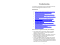
User’s Manual for ™ SafeConnect Summit Technology, Inc. Walnut Creek, CA 94597 Tel: 1-925-944-1212 Fax: 1-925-944-7126 [email protected] http://www.powersight.com Rev 2 Copyright 2007 by Summit Technology PowerSight is a registered trademark and SafeConnect is a trademark of Summit Technology, Inc. SafeConnect conforms to UL STD 61010-1:2004, is certified to CAN/CSA C22.2 number 61010-1:2004, and complies with the requirements of IEC61010-1:2001 for a rated input of 600V, measurement category III, pollution degree II, basic insulated electronic device. SafeConnect is not to be connected to a source greater than 600V phase-to-phase or phase-to-neutral. SafeConnect is designed to only be used with the PowerSight model PS4000 meter, with the SafeConnect Adapter accessory attached to it. Do not use it with any other adapter or meter since that might damage SafeConnect, pose an immediate or future safety risk, or damage or affect the power service connected to SafeConnect. There are no user serviceable parts in your SafeConnect accessory. Opening the case voids your warranty and may result in present or future danger to users of the meter. Cleaning is to be done by use of a dry or damp piece of cloth. Grease may be removed by light application of isopropyl (rubbing) alcohol. Do not use water or other conductive liquids since they may pose a safety risk. Use of this equipment in a manner not specified by Summit Technology can result in injury and voiding of warranty. SafeConnect is manufactured by Summit Technology, Inc in the U.S.A. The standard warranty period is 12 months from date of purchase. We encourage you to advise us of any defects of design or manufacture of any of our products. We are dedicated to your successful use of the product. Table of Contents Introducing SafeConnect..........................................................4 Safety Features of SafeConnect................................................................. 4 Time-Saving Features of SafeConnect...................................................... 4 Error Prevention Features of SafeConnect ............................................... 5 Installing SafeConnect ..............................................................6 Introduction..................................................................................................... 6 Required Tools .............................................................................................. 6 Supplied Parts ............................................................................................... 7 Installation Instructions................................................................................. 8 Connecting PowerSight to the SafeConnect Adapter ....12 Introduction................................................................................................... 12 Connection Procedure................................................................................ 12 Verifying Operation Using PowerSight...............................13 Preparation................................................................................................... 13 Checkout Procedure ................................................................................... 13 Using SafeConnect ..................................................................16 Overview....................................................................................................... 16 Troubleshooting........................................................................17 Observations................................................................................................ 17 Specifications* ..........................................................................21 3 Introducing SafeConnect Congratulations on your decision to buy the SafeConnect accessory for PowerSight! You have just purchased an accessory that offers significant advantages over conventional ways of temporarily monitoring and measuring of power systems. The philosophy of the product is to give you the measurements you need with a minimum of risk, error, and trouble. The need to wear special gloves, eyewear, or flame-retardant clothing is eliminated when monitoring power. Setting up and tearing down a test setup becomes dramatically faster. With a quarter turn of the wrist, you can feel secure that your connections are correct and the data will be what you expect. Safety Features of SafeConnect 1. The electrical panel no longer needs to be opened to perform measurements, thus avoiding exposure to dangerous voltages. 2. Output pins of the exposed connector are deactivated when not in use, thereby preventing exposure to dangerous voltages. 3. Voltage inputs to SafeConnect are fused with 600 V fuses. 4. All components are specified to operate on up to 600 Vrms systems for measurement cat III conditions. 5. The connector and mounting screws of SafeConnect do not protrude more than 0.4” from the panel. 6. Voltages representing the flow of current are less than 2 Vrms on the exposed connector. 7. Shorting any of the contacts of the exposed connector will not result in damage or result in voltage exposure. Time-Saving Features of SafeConnect 1. The panel does not need to be opened every time a measurement is needed, thus saving time 4 2. The connection to three-phase power is made with a quarterturn of a connector, saving time for performing spot checks, such as for performing on-line motor diagnostics. Error Prevention Features of SafeConnect 1. The connection is made to a single pre-installed connector, thus eliminating connection errors and ensuring good data results. 2. The panel does not need to be opened, which prevents possible damage from occurring inside the panel during hookup and tear-down of the measurement session. Compatibility with PowerSight Meters SafeConnect is designed for use with models PS4500 and PS4000 without modification or firmware upgrade. Models PS3000 and PS250 must have their hardware modified to work with SafeConnect. If the modification is done after initial purchase of the meter, there will be a charge. All meters require a SafeConnect Adapter in order to interoperate with SafeConnect. 5 Installing SafeConnect Introduction SafeConnect comes to you as a kit to be installed in a motor control center or other electrical panel. The standard version is for connection to three-phase circuits without neutral. The SafeConnect-N model (“N model”) is for connection to threephase circuits with neutral. Installing the product requires the following: 1. You must read all the installation instructions before proceeding. 2. You will need to power down the panel that is to be modified. 3. You will need to temporarily remove each phase conductor in order to slip a sensor over it (unless your kit includes split-core CTs). 4. You will need to drill several mounting holes in the electrical panel. 5. You will need to fully install the kit before the panel will be safe to leave unattended. 6. You will need to buy and install a SafeConnect Adapter accessory for your meter before you can obtain the benefits of the installed SafeConnect. SafeConnect is intended to be a permanently installed piece of equipment. Installation must follow the instructions exactly and it must in no way be allowed to decrease the safety or effectiveness of the panel that is modified. Required Tools 1. Center punch (for locating holes to the panel) 2. Hole cutter, 2-1/8 inch in diameter (for the connector to protrude through the panel). Possible suppliers and part numbers are the Jancy SM212 or the Unibit 362 (available from Graybar). 3. 1/2” shank capacity electric drill (for driving the hole cutter bit) 6 4. 11/64 drill bit (for drilling the panel for mounting screws) (#16 bit is also acceptable) 5. Screw-driver or other tool of the type required to remove or open the front panel of the electrical panel you will be modifying. 6. Phillips head screwdriver, #2 (for mounting SafeConnect to the panel) 7. 11/32” nut driver or wrench for (for mounting SafeConnect to the panel) 8. Very small standard slot screwdriver (for screwing down the wires from the current sensors) 9. Tie wrap gun or metal cutters (for installing nylon tie wraps to organize and route the cables to SafeConnect) 10. Screwdriver, Allen head wrench, terminal crimp tool, or whatever is needed to make the connections to the voltage sources in the panel and to connect the ground lead to an acceptable ground. 11. PowerSight meter to verify that the panel is de-energized and later to verify that the connections are all correct. 12. SafeConnect Adapter accessory to connect to your PowerSight analyzer to verify that the connections are all correct and the product is functioning correctly. 13. Personal protective equipment (PPE): safety gloves, eye shield, and clothing meeting OSHA safety requirements for working on a live panel of the type you are modifying. Supplied Parts 1. SafeConnect box with 6 foot voltage leads and 6 foot ground cable attached to it (3 voltage leads for normal kit, 4 for “N model”) 2. (optional) plastic safety cap on the large connector of SafeConnect (for limited protection for the connector from being hit or having corrosive or conductive material entering it from the outside) 3. Current sensors (3 for normal kit, 4 for “N model”) 4. 8-32 x ½” Phillips head cap screws (4 for attaching SafeConnect to the front panel) 5. 8-32 locknuts (4 for attaching SafeConnect to the front panel) 7 6. flanged spade lug for optional attachment to the unterminated end of the ground lead 7. 15 nylon tie wraps for organizing and installing the cables 8. Paper template for drilling the mounting holes 9. this manual Note: The SafeConnect Adapter accessory must be ordered separately. Installation Instructions For your safety and the safety of others, you must follow these instructions exactly. If you feel there are any errors in this procedure or are unsure about any step, please notify technical support personnel of Summit Technology, prior to proceeding, at 925-944-1212 or [email protected]. 1. Insure that you have all necessary tools. See the Required Tools section above. 2. Insure you have all required parts. See the Supplied Parts section above. 3. Prior to proceeding, determine how the panel is attached to its cabinet. If it is connected via a hinge, verify that you will be able to swing it open sufficiently to work on it and to install SafeConnect to the back of the panel. If the panel must be removed from the electrical cabinet, make sure that you have a work space that will allow you to work on it that will not stretch any wires that are attached to it during modification. 4. Power down the panel to be modified. Observe your company’s lockout/tagout procedures. 5. Remove the front panel by either swinging it open from the cabinet or placing it on a suitable work space that allows you to work both on the panel and inside the cabinet. 6. Wearing your safety equipment and using your PowerSight analyzer or voltmeter, verify that power has been removed from the electrical panel that is now exposed. Verify this by measuring the voltage from phase to phase and from phase to neutral or ground at the points that are normally 8 activated. Consult your PowerSight analyzer manual for how to connect to or measure voltage 7. Verify that you can mount SafeConnect to the inside of the panel without it coming within unacceptable distance of the internal components of the electrical panel. Keep in mind that SafeConnect is about 5.5” x 8.5” and it will extend about 2 inches deep into the panel. Allow at least 1 inch of air gap between this metal box and internal components and wiring inside the panel for low voltage installations (600Vrms or less). 8. Determine the safe and convenient location for SafeConnect to be located on the front panel. This position must impose no safety hazard on the inside of the panel and should be at a convenient position for easy attachment at the front of the panel. Consideration should also be given to locating it so that the protruding connector of SafeConnect will be unlikely to be hit or catch on anything on the outside. 9. Attach the included paper template to the outside of the panel in the safe and convenient location that you have identified, using tape or other temporary adhesive. 10. Center tap the five indicated holes through the template. 11. Remove the template. 12. Use your electric drill with 11/64 drill bit (or #16) to drill out the 5 holes. 13. Use your hole cutter to create a 2-1/8” hole for the large connector of SafeConnect. 14. Collect and remove all metal cuttings from the inside of the panel that resulted from the drilling. 15. Attach SafeConnect to the inside of the front panel. Attach it by passing the four 8-32x1/2 Phillips cap screws through the front panel then through SafeConnect and secure them with the #8 locknuts included in the kit. 16. Considering where the voltage connections will be made, determine how the wires will be routed from SafeConnect to their destinations. Consider that extra length will be required if the panel is removed later and placed on the floor. Consider that if the panel is hinged, the wires will flow to the hinge side of the cabinet and sufficient extra 9 wire will be needed at the hinge to allow the panel to swing open very wide without stretching the cables. Also consider that excessive loose wire may droop across hot components, get nicked or pinched when the panel is closed, or rub against sharp edges that could degrade the insulation. Use the included tie wraps or another preferred and safe method for dressing the leads together, routing them to the proper destinations, and anchoring them along the way. Cut off any excess length. 17. Disconnect the A, B, and C phase conductors that you wish to monitor. Normally, these would be on the output (the load side) of a switch, contactor, or breaker. If you are installing an “N model”, also disconnect the neutral conductor. 18. Identify each sensor by observing the labels on the wires where they attach to each sensor. 19. Slip the A phase current sensor over the A phase conductor, the B phase sensor over the B phase conductor, and the C phase sensor over the C phase conductor. Important: Make sure that the side of the sensor with the small white dot or the direction of the arrowhead faces in the direction towards the load. If you are installing an “N model”, also slip the neutral sensor over the neutral conductor. 20. Reattach each conductor to its original position and attach the voltage lead at the same time in some safe and permanent way. Typically, this may require stripping insulation away and twisting the wire around some connection point or between the conductor and a clamping point. Make all connections in accordance with your local electric codes. Identify each voltage lead by comparing its color to the label where it enters the SafeConnect box. 21. Determine how the current sensor wires will be routed from the sensors to SafeConnect. 22. Use the included tie wraps or another safe method for dressing the current leads together, routing them to the proper places, and anchoring them along the way. We recommend that any excess be looped together and tie wrapped safely out of the way. If you choose to cut off excess wire length, be certain that you attach each shortened and stripped wire to the same position on the terminal block connector that it was previously connected 10 to. The proper connection order can be seen in the picture at right. The “+N-” connections only exist in the –N model. The black wire from each CT attaches to the “-“ terminal position. The “+” connection will be to a white or red wire, depending on the kit. Caution: Measurements will not be correct if this connection is not made correctly! 23. Use a small screw driver to verify that each terminal of the tie-down block is tight and each wire is secure in its connection. 24. Plug the terminal block connector into its mate in SafeConnect. If the terminal block connector is a six wire type, plug it into the leftmost position, leaving the rightmost two positions empty. Make sure it is fully seated into its mate. 25. Verify that the green ground lead is securely attached to SafeConnect. 26. Identify a good grounding point for attachment of the green grounding lead coming out of SafeConnect. 27. Attach the green grounding lead of SafeConnect to the ground point. You may use the flanged spade terminal that is included in the kit if that is useful for a good connection. Follow local electric codes in shortening the ground lead (if required) and in attaching the ground lead to a good grounding point. 28. Reattach the front panel or if it is mounted on a hinge, swing it shut and tighten any retaining screws. 29. If a plastic safety cap is supplied, install it on the output connector of SafeConnect. 30. This completes the installation. 11 Connecting PowerSight to the SafeConnect Adapter Introduction PowerSight analyzers have individual inputs for each voltage and current of each phase and neutral. However, the output of SafeConnect is a single large connector. Therefore, a special adapter is required to allow PowerSight to accept the output of SafeConnect. The SafeConnect Adapter starts with a large mating connector for the large connector of SafeConnect and ends with individual cables for connections to each of the voltage and current inputs. The standard model has connections for voltage and current for three phases. The “N model” also has connections to the neutral voltage and current inputs of PowerSight. If the SafeConnect LDC (Line-to-DC) option is present, you will want the “LDC option adapter” so you can power your PowerSight meter from the SafeConnect connector. Connection Procedure Each cable is labeled at its end. Simply plug each cable into its mating and similarly identified jack in PowerSight. 12 Verifying Operation Using PowerSight Preparation At this point, the installation of SafeConnect should be completed and the front panel is secured (see the “Installing SafeConnect” chapter). Checkout Procedure 1. Re-apply power to the electric panel. If this is successful, proceed. If not, power back down and use industry safe practice to open the panel again and troubleshoot why power could not be applied successfully. 2. Connect the SafeConnect Adapter to PowerSight (see the “Connecting PowerSight to the SafeConnect Adapter” chapter. 3. Remove the protective plastic cap from the large SafeConnect connector and put it in a safe place. 4. Attach the large connector of the SafeConnect Adapter to the large connector of SafeConnect by inserting it into its mate and turning clockwise ¼ turn. 5. Turn PowerSight on. If you have the SureStartTM feature in your meter (models PS4500 & PS250), observe that it has identified the correct power system and presents no possible errors in the connections. If it shows incorrect system parameters or presents possible errors, proceed to the Troubleshooting section. If all appears well, proceed to step 13. If your meter does not have the SureStartTM feature, proceed to the next step. 6. If you have the Checkout Connections feature (models PS4000 & PS3000), press the [Setup] key of PowerSight and then press [Yes] when it asks if you wish to “Checkout Connections”. 7. The first screen displays all voltage phases. Note that to conserve display 13 space, the summary for the third phase does not have “V” displayed. Thus, “cn=277” means Vcn is 277 Vrms. Check that the voltages displayed are correct. If they are, proceed to the next step. If they are not, proceed to the Troubleshooting section. 8. Still viewing the voltages, disconnect the Ia current cable from PowerSight and verify that the voltages drop to 5 or less volts. If this happens, reattach the Ia cable, press the [Yes] key, and proceed to the next step. If the voltages remained greater than 5V, proceed to the Troubleshooting section. 9. The next screen shows the phase relationship between the voltage phases. Normally, the voltages will be listed in order of Va, Vb, and then Vc, with roughly 120 degrees between them. If they appear correct, press [Yes] and proceed to the next step. If they are not, proceed to the Troubleshooting section. 10. The next screen shows the currents in each phase and neutral. The panel must be under load for this step to be performed. If it is not under load, either activate the load or wait for the load to be activated. When the load is active, examine the current readings of each phase and neutral to see if they appear to be correct. If they are, press [Yes] and proceed to the next step. If they are not, proceed to the Troubleshooting section. 11. The next screen shows the phase relationship between the current phases. The panel must be under load for this step to be performed. Normally the currents will be listed in order of Ia, Ib, and then Ic. In any case, they must be in the same order that the voltages were listed when their phase relationships were listed. Normally, the currents will be roughly 120 degrees apart. If it is a 4-wire delta service, they may be more roughly 90, 90, and 180 degrees apart. If they appear correct, press [Yes] and proceed to the next step. If they are not, proceed to the Troubleshooting section. 14 12. The final screen shows the phase relationship between the voltage and current of each phase. The panel must be under load for this step to be performed. They should be roughly similar in phase lag. If any angle extends outside of the range of +/-90 degrees, then there is a connection problem, proceed to the Troubleshooting section. If the phase lags look correct, you likely have a successful installation. 13. If the meter has the AMD (Advanced Motor Diagnostics) option installed and activated, do a motor analysis and upload the data later as a record of the successful installation. If the meter does not have the AMD option or it is inactive, press the [Wave] button to make a record of the voltages and currents and upload that .wfm file at a later time. 14. Disconnect the SafeConnect Adapter from SafeConnect and reinstall the protective plastic cap over the large connector of SafeConnect. 15 Using SafeConnect Overview Once SafeConnect is installed and its operation is verified, it is ready for use. To use SafeConnect for taking measurements, follow these steps: 1. Attach the SafeConnect Adapter to your PowerSight meter. Review the “Connecting PowerSight to the SafeConnect Adapter” chapter, if necessary. 2. Remove the protective plastic cap from the large SafeConnect connector and put it in a safe place. 3. Attach the large connector of the SafeConnect Adapter to the large connector of SafeConnect by inserting it into its mate and turning clockwise ¼ turn. 4. Turn PowerSight “on” if it is not already. You can now operate PowerSight fully. You may take spot readings, such as for on-line motor diagnostics (with the AMD option installed in PowerSight) or you may leave the meter hanging from the SafeConnect Adapter for longer monitoring sessions. If the LDC option for SafeConnect is installed, it will power itself from the monitored voltages. 16 Troubleshooting This chapter is organized as a series of observations, their likely causes, and the suggested remedial action to take. Observations Power cannot be reapplied successfully after installation SureStart suggests a wiring error has occurred Voltages are not balanced Voltages are present on PowerSight even when the Ia current cable is removed The phase sequence of the voltages is not in the order of Va, Vb, Vc The phase angle between the voltage phases is not roughly 120 degrees The currents are not of the expected magnitude The phase sequence of the currents is not in the same order as the voltage was The phase angle between the current phases is not roughly 120 degrees The phase lag between voltage and current of a phase is outside the range of +/-90 degrees The protective plastic cap for the connector of SafeConnect is missing Power cannot be reapplied successfully after installation If the voltages are no longer present, check for a problem upstream of the connections. Has the right switch been engaged to energize the circuit? If the problem was an explosion in the cabinet, a short circuit between the phases or to ground has probably occurred. Extensive damage has likely occurred. If there is an arcing or hissing sound, power down the panel, put on proper PPE (such as low voltage gloves, face shield, and Nomex clothing), and observe industry safety procedures for working in or around energized equipment as you open the panel and look for a loose connection. 17 SureStart suggests a wiring error has occurred SureStart is probably correct. Investigate and correct the connection. Voltages are not balanced There is likely a problem with the connection to one or more of the voltages. Power down the panel. Power down the panel, put on proper PPE (such as low voltage gloves, face shield, and Nomex clothing), and observe industry safety procedures for working in or around energized equipment as you open the panel and check the connections. If the connections are good, the problem may be in SafeConnect, the SafeConnect Adapter, or PowerSight. Try using different meters or adapters to narrow down the problem. Voltages are present on PowerSight even when the Ia current cable is removed SafeConnect is damaged internally and will need to be returned for repair. Contact [email protected] to arrange for obtaining a temporary replacement or block-off plate. Removing SafeConnect from the panel without installing a replacement SafeConnect or block-off plate will result in exposure to hazardous voltages when the cabinet is re-energized. Voltages in excess of 5V should never appear on the output of SafeConnect unless the SafeConnect Adapter is connected to it and the Ia current cable is plugged into an operating PowerSight analyzer. This safety failsafe feature is being patented by Summit Technology Inc. The phase sequence of the voltages is not in the order of Va, Vb, Vc Unless this is the correct phase sequence for this panel, two of the voltage leads have been switched. Power down the panel, put on proper PPE (such as low voltage gloves, face shield, and Nomex clothing), and observe industry safety procedures for working in and around energized equipment as you open the panel and determine which two connections have been reversed. 18 The phase angle between the voltage phases is not roughly 120 degrees Generally this will only occur if: two of the phases are supplied from the same point, one or two of the voltages are not connected, or you are connected to a 4-wire delta in phase-neutral voltage measurement mode. The currents are not of the expected magnitude The likely cause is: One or more of the wires from the sensors may not be properly connected to SafeConnect, one of the sensors is not installed on its phase conductor, the sensor is defective, the load is not actually on, or there is a problem with the connection inside SafeConnect, the SafeConnect Adapter, or in PowerSight. Attempt to narrow this down through inspection and substitution. The phase sequence of the currents is not in the same order as the voltage was Assuming the voltages are of the correct sequence, two of the current sensors have been switched. Power down the panel, put on proper PPE (such as low voltage gloves, face shield, and Nomex clothing), and observe industry safety procedures for working in or around energized equipment as you open the panel and determine which two are on the wrong conductors. The phase angle between the current phases is not roughly 120 degrees Generally this will only occur if: two of the sensors are on the same conductor, one or two of the current sensors are not connected, one or more of the sensors have been installed on their conductor backwards, or you are connected to a 4-wire delta with significant singlephase or two-phase loads. 19 If a current sensor has been installed backwards, you may wish to simply switch the two output wires where they plug into SafeConnect. The phase lag between voltage and current of a phase is outside the range of +/-90 degrees Either the current sensor is backwards, is connected to the wrong conductor, or both. The protective plastic cap for the connector of SafeConnect is missing The cap is not required, but is useful. It prevents the connector from grabbing on clothing, gives it some protection from being hit, and prevents conductive or corrosive materials from getting into the contacts. Voltages above 5Vrms are not present on the connector when the SafeConnect Adapter is not attached, so there is no safety issue due to dangerous voltage exposure if the plastic cap is lost. 20 Specifications* Size 8.5” Wide × 5.5” High × 1.75” Deep Weight Less than 2 pounds Operating Range 0 - 50 degrees C (32 - 122 degrees F) Relative humidity to 70% (non-condensing) Power Requirement Nominal power is supplied by attached PowerSight Input Voltage Input Range: 1 - 600 Vrms steady-state (direct input) Output Voltage <5Vrms when not connected to SafeConnect Adapter Accuracy: No distortion of the original voltage when connected to PowerSight Frequency Response No de-rating of accuracy for harmonics or transients Input Current Sensors convert to voltage <2Vrms prior to entry into SafeConnect. Current capacity dependent on current sensor ordered Output Current Measurement Accuracy: accuracy of probe Frequency Response: dependent on current probe attached No de-rating of accuracy for harmonics through 1500 Hz) Frequency Range: 20 - 66 Hz fundamental frequency Safety CE for a 600V cat III, pollution degree II, basic insulated UL STD 61010-1:2004 CSA/UL C22.2 number 61010-1:2004 * These specifications are subject to change without notice. 21