1
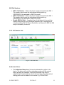
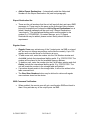
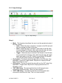
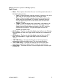
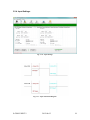
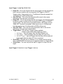
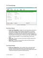
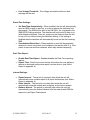
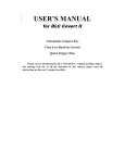
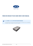
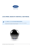
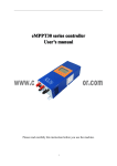
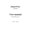
GSM COMMUNICATOR USER MANUAL Revision History Rev 1.0………………………………………2013-05-20 Rev 1.1………………………………………2013-06-03 Rev 1.2………………………………………2013-06-25 Rev 1.3………………………………………2013-07-15 Rev 1.4………………………………………2013-09-09 Rev 1.5………………………………………2013-10-10 Rev 1.6………………………………………2013-11-12 Rev 1.7………………………………………2014-06-02 Rev 1.8………………………………………2014-10-16 Rev 1.9………………………………………2014-11-11 Rev 1.10………………………………..……2014-12-09 Rev 2.1………………………………..……..2015-01-22 Rev 2.2………………………………..……..2015-04-02 S-GSM-C/REV2.2 2015-04-02 2 Table of Contents 1. INTRODUCTION .......................................................................................................... 4 2. SPECIFICATIONS AND FEATURES .......................................................................... 5 2.1. Hardware .................................................................................................................. 5 2.2. Software ................................................................................................................... 5 3. BASIC SETUP................................................................................................................ 6 3.1. Connection and Communication.............................................................................. 7 3.2. Customisation ........................................................................................................ 12 3.2.1. SMS / GPRS Settings: .................................................................................... 12 3.2.2. Cell Number List: ........................................................................................... 14 3.2.3. Output Settings: .............................................................................................. 16 3.2.4. Input Settings: ................................................................................................. 18 3.2.5. General Settings .............................................................................................. 20 3.2.6. Network Profiles: ............................................................................................ 22 3.2.7. Credit Settings:................................................................................................ 23 3.2.8. Saving/Loading Custom Settings Profiles: ..................................................... 25 4. LED Indicator ............................................................................................................... 25 4.1. Unit Activated: ....................................................................................................... 25 4.2. GSM Set-Up: ......................................................................................................... 26 4.3. Network Registration Successful – Good Signal:.................................................. 26 4.4. Network Registration Successful – Low Signal: ................................................... 26 4.5. PIN Error:............................................................................................................... 27 4.6. Service Mode: ........................................................................................................ 27 S-GSM-C/REV2.2 2015-04-02 3 1. INTRODUCTION The GSM Communicator provides a stable and versatile platform for customers wishing to add remote switching and monitoring functionality to a wide variety of applications. The unit supports both SMS and GPRS communication options and offers multiple input, as well as output peripherals. The GSM Communicator is ideally suited to batterypowered applications where effective power management is critical. The device may be used as a stand-alone unit that interfaces to one, or many cell phones. Alternatively, the Sentry GSM Communicator may be used in conjunction with the Sentry GPRS server infrastructure, offering a full remote management solution that is robust, as well as cost-effective. The device contains a unique “virtual wallet” feature that allows credits to be loaded onto the device. When an input pulse is detected, the unit determines if credit is available. If so, the pulse is reproduced on an output port and a credit is deducted. The Sentry GSM Communicator is simple to set up and operate. A tri-colour LED indicates normal operation, fault conditions and adequate signal strength. All settings on the unit may be retrieved and altered remotely by an authorized user. S-GSM-C/REV2.2 2015-04-02 4 2. SPECIFICATIONS AND FEATURES 2.1. Hardware - 2 x relay outputs (5A, 220V AC, 28V DC) - 1 x digital output (0V low, 5V high) - 2 x digital inputs (0V - 24V DC) - Supply requirements: (12V, 500mA) - External UART (3.3V or 12V) - External I2C bus - Real time clock/calendar with power backup - Dual SIM - Status indication LED (Tri-colour) - Quad-band GSM module (Class 10 GPRS) - External SMA connector - Low-power standby mode 2.2. Software - SIM pin lock - GPRS with SMS fail-over or SMS only - Application server (GPRS, SMS-to-TCP/IP) with management software - Intuitive application software - 3 time-settable modes available per output port (latch, toggle, pulse) - Output port activation via SMS or missed call (optional confirmation via SMS) - Up to 2 master (can alter settings remotely) users and 500 regular users - User-settable input activation trigger-duration - Input activation on high or low trigger - SMS alerts sent concurrently to up to 5 destinations S-GSM-C/REV2.2 2015-04-02 5 3. BASIC SETUP Fig. 3.1 – GSM Communicator connection terminals NC1 NORMALLY CLOSED (REL 1) 3V 3V OUT NO1 NORMALLY OPEN (REL 1) CLK SERIAL CLOCK CMN1 COMMON (REL 1) DAT SERIAL DATA NC2 NORMALLY CLOSED (REL 2) IN1 INPUT 1 NO2 NORMALLY OPEN (REL 2) IN2 INPUT 2 CMN2 COMMON (REL 2) OUT DIGITAL OUTPUT RX UART RECEIVE 12V 12V SUPPLY TX UART TRANSMIT GND GROUND S-GSM-C/REV2.2 2015-04-02 6 3.1. Connection and Communication Step 1: Unscrew the front panel of the enclosure and remove the board from the enclosure. The board should slide out easily without excessive force needing to be applied. PRIMARY SIM SECONDARY SIM Fig. 3.2.1 – SIM card holders Slide open the primary SIM cardholder labelled “PRI” (see Fig. 3.2) and insert the SIM card. Lock the SIM card in place once inserted. If a second SIM is desired for backup purposes, then this SIM card should be placed in the secondary SIM cardholder labelled “SEC.” Step 2: Place the board on a non-conductive surface (e.g. A wooden table or a book). Connect the 12V and ground terminals to a suitable power supply. You should see the LED light up red and then flash green, indicating that power is connected and the unit is operating normally. S-GSM-C/REV2.2 2015-04-02 7 Step 3: Ensure that the correct USB drivers are installed on the PC being used. Drivers can be found on the supplied data pack or may be downloaded from: http://www.ftdichip.com/Drivers/VCP.htm Connect the USB programmer board to the cable supplied, and connect the other side of the cable to the PC. DO NOT CONNECT TO THE DEVICE YET. A new USB Serial COM port should be visible under: System Properties>Hardware>Device Manager>Ports Fig. 3.2.2 – Windows Device Manager If the USB Serial Port has not been assigned a COM port (COM21 above) then update the driver and point to the CDM v2.08.28 Certified parent folder. The operating system will automatically select the correct driver within this folder. Fig. 3.2.3 – USB Device Driver S-GSM-C/REV2.2 2015-04-02 8 Fig. 3.3 – USB Programmer board connection Insert the programmer pins into the terminals of the main board as shown in Fig. 3.3. The pin labels on the programmer board should correspond to the terminal labels on the main board as follows: RX connected to RX TX connected to TX 3V connected to 3V CLK connected to CLK Tighten the screws on the terminals to ensure a good electrical connection. S-GSM-C/REV2.2 2015-04-02 9 Step 4: Ensure that Microsoft .NET Framework 4.0 or higher is installed on the PC. Install the Sentry GSM Management Tool software package from the CD provided or from the Downloads section on the Sentry website. A shortcut icon should appear on the desktop once successfully installed. Open the Sentry GSM Management Tool. Fig. 3.4 – Dashboard view The program will open to the Dashboard view. S-GSM-C/REV2.2 2015-04-02 10 Step 5: Click on the GSM Setup icon then click on the Serial Interface option at the top left of the page. Fig. 3.5 – Serial interface connection A dropdown box should appear. Select the COM port associated with the USB/Serial adaptor and click OK. The software will indicate the connection status at the bottom right of the page. The software will ask if the unit settings should be imported click OK. This will populate all the software fields with the exact settings currently stored on the unit. Fig. 3.6 – Read Settings From Unit S-GSM-C/REV2.2 2015-04-02 11 3.2. Customisation 3.2.1. SMS / GPRS Settings: Fig. 3.7 – SMS / GPRS Settings Communication Mode: GPRS with SMS Fail-Over – All alert and report messages are sent via the GPRS network as default. If the GPRS message fails to be sent, the unit will re-send the message to all Report Destination Numbers (see 3.2.2) via SMS. Note: The GPRS feature requires subscription, please contact Sentry. GPRS without SMS Fail-Over – All alert and report messages are sent via the GPRS network as default. If the GPRS message fails to be sent, the message will be discarded and lost. SMS Only – All alert and report messages are sent via SMS to all Report Destination Numbers. S-GSM-C/REV2.2 2015-04-02 12 SIM Settings: Active SIM Card – This refers to the SIM tray that will be accessed by the unit as default. SIM 1 refers to the primary SIM tray and SIM 2 refers to the secondary SIM tray. SIM 1 PIN – If the primary SIM card is password protected, the password may be stored here. The unit will automatically enter the correct password on start-up. SIM 2 PIN – If the secondary SIM card is password protected, the password may be stored here. The unit will automatically enter the correct password on start-up. Note: For both SIM cards, the password cannot be set or changed on the actual SIM card from the PC, this can be done from any mobile device. Server Settings: Only applicable if used in GPRS mode Account No. – Unique number assigned to the user when signing up to the Sentry GPRS service. IP Address – The TCP/IP address that the unit will attempt to establish a connection with. Port – The TCP/IP port that the unit will attempt to open. SMS to SSMI – When in SMS Only mode, the GSM unit will send an SMS to the SSMI server as well as to all SMS Report Destinations. Resp. to SSMI – If enabled, GSM unit will respond to all Report Destinations if a SMS command is received (E.g. Balance). Identification Settings: SMS Header Text – The text that will be displayed at the top of all messages and alerts. Can be customised to reflect a site or client name. IMEI No. – The International Mobile Equipment Identity number of the GSM module. Network Code – Can be used to lock the unit to a specific network using the network-specific identity code. 0 denotes automatic selection of network (recommended). Missed Call Function: This sets the output port that will be activated if a missed call is received. The output port will be activated subject to the output settings chosen (see 3.2.3). Please note: The mobile device that initiates the call to the Sentry GSM Communicator must have the “Send Caller ID” enabled which displays the caller’s number on the device being called. S-GSM-C/REV2.2 2015-04-02 13 SIM Cell Numbers: SIM 1 Cell Number – This is the phone number associated with SIM 1. The number must include the international dialling prefix e.g. 27827824532. Not applicable in SMS Only mode. SIM 2 Cell Number – This is the phone number associated with SIM 1. The number must include the international dialling prefix e.g. 27827824532. Not applicable in SMS Only mode. Enable SIM Fail-Over – If enabled, the unit will attempt to log onto the network using the fail-over SIM should signal be lost or registration fail using the primary SIM. All Report Destinations will be sent a SMS if a SIM swap is initiated by the device. 3.2.2. Cell Number List: Fig. 3.8 – Cell Number List Authorised Users: The Authorised Users have full remote administration rights to the device. The device will verify the originating number with the network before allowing any changes. A second Authorised User may be added/deleted remotely by the other Authorised User. The international dialling prefix must be added to the number E.g. 27834876542 S-GSM-C/REV2.2 2015-04-02 14 Add to Report Destinations – Automatically adds the Authorised Numbers to the Report Destinations list (see next paragraph). Report Destination No.: These are the cell numbers that the unit will send all alert and report SMS messages to. These may be the same as the Authorised User numbers but must be explicitly set (unless the Add to Report Destinations box is ticked). Identical messages will be sent to all 3 Report Destinations “concurrently.” The international dialling prefix must be added to the number E.g. 27834876542. On certain devices, up to 10 Report Destinations may be added, please contact Sentry should this be a requirement. Regular Users: Regular Users may activate any of the 3 output ports via SMS or missed call, but may not change any settings on the device remotely. Up to 100 regular users may be stored on the device at once. To add a new user, enter the number into the Cell Number window and click Add. Include the international dialling prefix. E.g. 27827813765. The number will be placed in the first available memory address. To delete a user, enter the number into the Cell Number window and click Delete. Include the international dialling prefix. E.g. 27827813765. The unit will locate the number in the storage table and delete it. If a number already exists in the storage table, it will not be written to the table a second time. The Read User Numbers button may be clicked to retrieve all regular user numbers stored on the device. SMS Command Verification: When enabled, the remote user will get a confirmation SMS sent back to them if they activate any of the output ports via SMS. S-GSM-C/REV2.2 2015-04-02 15 3.2.3. Output Settings: Fig. 3.9 – Output Settings Relay 1: Mode – This dropdown box allows the user to set the operational mode of the relay namely: o Latch – When the relay is activated, it remains in the ON state until the user changes the state of the relay. o Pulse – When the relay is activated, it will remain in the ON state for a pre-defined On Duration, after which time the relay will revert back to the OFF state until activated again by the user. o Toggle – When the relay is activated, it will remain in the ON state for a pre-defined On Duration, after which time the relay will toggle states and remain in the OFF state for a pre-defined Off Duration. The cycle will repeat until the user disables the relay. On Duration – The time for which the relay will be in the ON state. Only applicable in Pulse and Toggle modes. May be set in varying intervals from 0.5 seconds to 1 hour. Off Duration – The time for which the relay will be in the OFF state. Only applicable in Toggle mode. May be set in varying intervals from 0.5 seconds to 1 hour. “ON” SMS String – The exact text that the unit will recognise as a command to activate the relay. This is not case sensitive. “OFF” SMS String – The exact text that the unit will recognise as a command to deactivate the relay. This is not case sensitive. S-GSM-C/REV2.2 2015-04-02 16 Relay 2: Identical in operation to Relay 1 (above) Digital Output: Mode – This dropdown box allows the user to set the operational mode of the digital output namely: o Latch – When the digital output is activated, it remains in the active state until the user changes the state of the digital output. o Pulse – When the digital output is activated, it will remain in the active state for a pre-defined On Duration, after which time the relay will digital output back to the inactive state until activated again by the user. o Toggle – When the digital output is activated, it will remain in the active state for a pre-defined On Duration, after which time the digital output will toggle states and remain in the OFF state for a pre-defined Off Duration. The cycle will repeat until the user disables the digital output. On Duration – The time for which the digital output will be in the ON state. Only applicable in Pulse and Toggle modes. May be set in increments of 10msec. Off Duration – The time for which the digital output will be in the OFF state. Only applicable in Toggle mode. May be set in increments of 10msec. “ON” SMS String – The exact text that the unit will recognise as a command to activate the digital output. This is not case sensitive. “OFF” SMS String – The exact text that the unit will recognise as a command to deactivate the digital output. This is not case sensitive. Active State – This allows the user to set the digital output to active high or active low. S-GSM-C/REV2.2 2015-04-02 17 3.2.4. Input Settings: Fig. 3.10 – Input Settings Fig. 3.11 – Input Functional Diagram S-GSM-C/REV2.2 2015-04-02 18 Input Trigger 1: (see Fig 3.10 & 3.11) Delay ON – This is the duration that the input trigger must be activated for before an alert condition will be recognised (ON Trigger or ON/OFF Trigger mode). Value may be set in 10 millisecond intervals ranging from 10 milliseconds to 2500 milliseconds. Alert ON Text – This is the text string that will be sent to the remote destination if the input port is activated. Delay OFF – This is the duration that the input trigger must be deactivated for before an alert condition will be recognised (OFF Trigger or ON/OFF Trigger mode). The input will not recognise another “ON” signal until the “Delay OFF” duration is exceeded. Value may be set in 10 millisecond intervals ranging from 10 milliseconds to 65000 milliseconds. Alert OFF Text – This is the text string that will be sent to the remote destination if the input port is deactivated. Trigger Mode – The unit has 3 trigger modes available. Subject to the Active State (high/low) chosen. 1. ON Trigger – Input will trigger after the delay ON time only. 2. OFF Trigger – Input will trigger after the delay OFF time only. 3. ON/OFF Trigger – Input will trigger after the delay ON time and will trigger again after the delay OFF time is reached. Send Alert – This tells the unit whether or not it should send a remote alert via SMS/GPRS if the input port is triggered (subject to Trigger Mode). Active State – The user may set the input to trigger on a high or a low signal. Input Trigger 2: Identical to Input Trigger 1 (above) S-GSM-C/REV2.2 2015-04-02 19 3.2.5. General Settings Fig. 3.12 – General Settings Power Save Settings: Enable Low Power Mode – Enables the Low Power feature of the device. In this mode, the GSM module will log onto the network for 3 minutes, after which the GSM part of the unit will be disabled to conserve power consumption. The GSM module will automatically activate and log onto the network after the Sleep Time has expired or if an alert is triggered. The unit will remain on the network for a 3-minute period, after which the GSM module will again be disabled. The unit typically draws 3mA in sleep mode. Sleep Time – The time (in minutes) after which the GSM module will be activated periodically. Wake Time – The time (in minutes) after which the GSM module will return to Sleep Mode once awoken. Low Voltage Settings: Enable Low Voltage Alert – When enabled, the unit will send an alert message to all report destinations when the voltage falls below a set threshold. The alert status will only be reset once the voltage rises at least 1V above the threshold to prevent continuous alerting. S-GSM-C/REV2.2 2015-04-02 20 Low Voltage Threshold – The voltage value below which an alert message will be sent. Reset/Time Settings: Set Date/Time Automatically – When enabled, the unit will automatically send an SMS to itself on start-up, in order to retrieve the date/time from the network. The SMS will be sent to the SIM CELL No. populated in the SMS/GPRS Settings window. The date/time will only be set if there is no valid date/time detected. Once set, power may be removed from the unit for up to 30 min without losing the date/time setting. If this setting is disabled then the date/time will automatically be set on the first incoming SMS. Unscheduled Reset Alert – When enabled, an alert will be generated whenever a reset occurs that is not initiated by the device itself. E.g. If the power is removed and then replaced, which may indicate tampering. Real-Time Report: Enable Real-Time Report - Enables/disables the Real-Time reporting feature. Report Time - Sets the hour and minute value when the user wishes to receive an automatic daily status report from the device. (see Status Report in appendix A). Interval Settings: Report Interval – The period (in minutes) after which the unit will automatically issue a status report to all report destinations (see Status Report in appendix A). Reset Interval – The period (in minutes) after which the unit will automatically reset the modem and re-register on the home network. Balance Interval - The period (in minutes) after which the unit will automatically query the airtime balance from the network and SMS the response to all Report Destinations. S-GSM-C/REV2.2 2015-04-02 21 3.2.6. Network Profiles: Fig. 3.13 – Network Profiles Profile <1 - 5>: All 4 major networks in South Africa are pre-loaded into the device. The network profiles should only be altered if used outside South Africa or on a cellular network that is not already loaded. Improper alteration may affect the functionality of the device. Profile Name – The name that is associated with the cellular network. Net ID – The network identity code of the cellular provider. APN – The access point name associated with the GPRS network. Username – The username necessary to gain access to the GPRS network. Password – The password necessary to gain access to the GPRS network. SSMI No. – The number of the SSMI server associated with the cellular network. (Only applicable if utilising the Sentry Server option) Message Centre Number – The central message centre number associated with the cellular network. Balance USSD – The USSD code that the unit will use to query the airtime balance from the network. S-GSM-C/REV2.2 2015-04-02 22 3.2.7. Credit Settings: Fig. 3.14 – Credit Settings Credit Mode Settings: Credit Mode – This activates the “digital wallet” feature of the device. If this mode is enabled, any pulse detected on input 2 is verified against a credit value stored within the unit. The pulse is then replicated on the digital output port (subject to the digital output settings in 3.2.3). If operated in Pre-paid Mode, there must be a positive balance in the account for the input pulse to be reproduced on the output pin. If operated in Post-paid Mode, the pulse will always be reproduced but the number of input pulses is counted and can be retrieved at any time by an authorised user. Low Credit Alert – When enabled, an alert will be sent to all report destinations if the credit value falls below a set value. Low Credit Value – The value below which the Low Credit Alert will be sent. Add Credits – Adds credits to the digital wallet. Remove Credits – Deletes credits from the digital wallet. Clear Credits – Clears all credits in the digital wallet. Clear Coin Count – Deletes ALL credits in the digital wallet. Credit Balance – Indicates the total number of credits in the account. Last Action – Indicates the last action that was performed on the account as well as the amount of credits added/deleted. Coin Count – The total number of times that input 2 has been pulsed. S-GSM-C/REV2.2 2015-04-02 23 Enable Cash-Up Mode – This feature works in conjunction with the Data pin on the GSM unit. When the data pin is pulled low, the cash-up feature is initiated (NB: Do not apply a voltage above 3V to the data pin). When initiated, this feature will take a “snap shot” of the Coin Count and store it. The current value of the coin count will be sent to the Report Destination(s). Works in conjunction with the CLOSECASHUP command (see Appendix). Cash-Up – Amount stored in the Cash-Up memory location. A value of 0 indicates that the cash-up has been “closed.” Clear Cash-Up – Clears the value stored in the cash-up memory. Pulse Count Settings: Enable Pulse Count: When enabled, the unit will count each pulse received on the "INPUT 1" port. Pulse Count: Current pulse count reading. Clear Pulse Count: When enabled, the pulse count reading will be set to zero the next time settings are applied to the device. Enable Pulse Alert: When enabled, an alert will be sent to all report destinations when the pulse count equals the "Pulse Alert Value", or any multiple of this value thereafter. Pulse Alert Value: The value at which a pulse alert will be sent, or any multiple thereafter. S-GSM-C/REV2.2 2015-04-02 24 3.2.8. Saving/Loading Custom Settings Profiles: Fig. 3.15 – Loading Profiles The Sentry GSM Communicator is shipped with default values for all settings. In many cases, the user’s settings will deviate substantially from the default settings. In this case, the user may save their custom settings in a file using the Save Settings To File icon at the bottom of any of the GSM Setup tabs. When this icon is clicked, all settings from all GSM Setup tabs will be saved, regardless of which tab is currently displayed. To load a profile, click on the Production icon. Direct the software to the applicable Production (settings) File and select the COM port. Click on the Program Settings icon to upload the file. 4. LED Indicator The LED is used to indicate several states that the unit may enter. Below is a summary of these states and the associated LED indication pattern. 4.1. Unit Activated: This state is entered when the unit is first powered up or when the unit resets itself automatically. LED Pattern: <OFF><ON (red)(5 sec)> S-GSM-C/REV2.2 2015-04-02 25 4.2. GSM Set-Up: This indicates that the unit is successfully communicating with the GSM module and attempting to establish a valid network connection. LED Pattern: <ON (green)(100 msec)> <OFF (100 msec)> <ON (green)(100msec)> … <OFF (100 msec)> <ON (green)(100 msec)> … 4.3. Network Registration Successful – Good Signal: This indicates that the unit has successfully registered with the home network and the signal is okay (>85dBm) LED Pattern: <ON (green)(1 sec)> <OFF (1 sec)> <ON (green)(1 sec)> … <OFF (1 sec)> <ON (green)(1 sec)> … 4.4. Network Registration Successful – Low Signal: This indicates that the unit has successfully registered with the home network but the signal is low (<85dBm) and a different antenna or network should be considered. LED Pattern: <ON (green)(1 sec)> <OFF (1 sec)> <ON (red)(1 sec)> … <OFF (1 sec)> <ON (green)(1 sec)> <OFF (1 sec)> <ON (red)(1 sec)> … S-GSM-C/REV2.2 2015-04-02 26 4.5. PIN Error: This indicates that the PIN code that the user is attempting to supply the SIM card is incorrect. Please verify that the PIN is correct then reset power to the unit to restart. LED Pattern: <ON (red)(100 msec)> <OFF (100 msec)> < ON (red)(100 msec) > … <OFF (100 msec)> < ON (red)(100 msec) > … 4.6. Service Mode: This indicates that the unit has entered “service mode.” In this mode, no credits will be deducted from the digital wallet, and no coins will be counted. All other unit functions remain unchanged. Only applicable when Credit Mode is enabled. LED Pattern: <ON (red)(20 msec)> <OFF (20 msec)> < ON (red)(20 msec) > … <OFF (20 msec)> < ON (red)(20 msec) > … S-GSM-C/REV2.2 2015-04-02 27