1
Axxon Soft Inc
Axxon Smart Software Package
The User’s Guide
Version 1.0.5
Moscow 2009
Contents
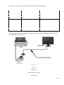
1
1.1
AXXON SMART INSTALLATION, UPDATING AND REMOVAL ...................................... 11
LICENSING METHOD............................................................................................................................. 11
1.2
THE AXXON SMART INSTALLATION KIT............................................................................................ 11
1.2.1 Drivers................................................................................................................................................ 12
1.2.2 Key file ................................................................................................................................................ 13
1.2.3 Additional components ...................................................................................................................... 13
1.3
AXXON SMART INSTALLATION .......................................................................................................... 14
1.4
AXXON SMART REMOVAL .................................................................................................................... 24
1.5
THE CONTENTS OF THE AXXON SMART PROGRAM FOLDER .......................................................... 29
1.5.1 Databases (data) .................................................................................................................................. 29
1.5.2 User manual (manual).......................................................................................................................... 30
1.5.3 Modules (modules) .............................................................................................................................. 31
1.5.4 Utilities (tools) ..................................................................................................................................... 31
1.5.5 Voice notification files (*.WAV) ............................................................................................................ 32
1.5.6 Smartphone......................................................................................................................................... 33
1.5.7 Smartppc ............................................................................................................................................. 34
1.5.8 Iface .................................................................................................................................................... 35
2
STARTING AND CLOSING THE AXXON SMART SOFTWARE ........................................ 35
2.1
GENERAL INFORMATION ......................................................................................................................... 35
2.2
STARTING AXXON SMART FROM THE WINDOWS START MENU .............................................................. 35
2.3
AUTOMATIC START ................................................................................................................................. 36
2.3.1 AXXON SMART in the Startup menu ..................................................................................................... 36
2.3.2 Automatic start of AXXON SMART on computer power-on instead of the standard Windows shell ....... 36
2.3.2.1
Setting up Windows to start with no password authorization....................................................... 37
2.3.2.2
Forced start of Explorer ............................................................................................................... 38
2.3.3 Start AXXON SMART as a service .......................................................................................................... 39
2.4
Closing AXXON SMART ............................................................................................................................ 40
2.5
POSSIBLE PROBLEMS AT AXXON SMART START-UP................................................................................. 41
2.5.1 Cards or guardant drivers not loaded ................................................................................................... 41
2.5.2 Key not found ...................................................................................................................................... 42
2.5.3 Key doesn’t match the card.................................................................................................................. 42
3
BASIC PRINCINPLES OF THE USER INTERFACE ............................................................. 43
3.1
MAIN CONTROL PANEL............................................................................................................................ 43
3.2
STARTING AND CLOSING THE USER INTERFACE ....................................................................................... 43
2
3.3
THE AXXON SMART SETTINGS PANEL ...................................................................................................... 44
3.3.1 General information ............................................................................................................................ 44
3.3.2 Opening and closing the Settings panel ................................................................................................ 44
3.3.3 IP devices creation wizard .................................................................................................................... 45
3.3.4 About .................................................................................................................................................. 49
3.3.5 Description of the Settings panel.......................................................................................................... 50
3.3.6 The Apply, Cancel and Close buttons .................................................................................................... 51
3.3.7 Object Settings panel ........................................................................................................................... 51
4
MACROS AND SCHEDULES ................................................................................................... 53
4.1
CREATING AND USING THE MACROS ....................................................................................................... 53
4.2
CREATING A SCHEDULE ........................................................................................................................... 54
5
VIDEO SUBSYSTEM ................................................................................................................ 55
5.1
GENERAL INFORMATION ......................................................................................................................... 55
5.2
VIDEO FORMATS ..................................................................................................................................... 55
5.3
THE VIDEO SYSTEM OBJECTS ................................................................................................................... 60
5.3.1 IP-devices ............................................................................................................................................ 60
5.3.1.1
IP-cameras .................................................................................................................................. 60
5.3.1.2
IP-Servers .................................................................................................................................... 60
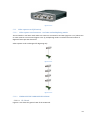
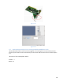
5.3.2 Video capture card (ES series) .............................................................................................................. 60
5.3.2.1
Video capture card resources – real time and multiplexing modes ............................................... 60
5.3.2.2
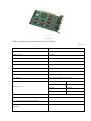
VIDEO CAPTURE CARDS SPECIFICATIONS ..................................................................................... 61
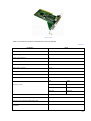
5.3.2.2.1 FS-5B card .............................................................................................................................. 61
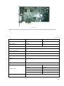
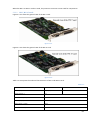
5.3.2.2.2 FS-6C, FS-16 cards (EXP) ......................................................................................................... 63
5.3.2.2.3 FS-8 card ................................................................................................................................ 65
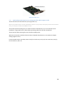
5.3.3 HARDWARE COMPRESSION CARDS ...................................................................................................... 66
5.3.3.1
Introduction ................................................................................................................................ 66
5.3.3.2
WS-7, WS-17 cards ...................................................................................................................... 67
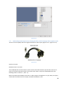
5.3.4 Analog video out card installation ........................................................................................................ 69
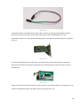
5.3.5 The D-SUB/BNC-XX interface cable ....................................................................................................... 70
5.4
HARDWARE INSTALLATION AND SETUP .................................................................................................. 71
5.4.1 FS-6C card setup .................................................................................................................................. 71
5.4.1.1
FS-6C card installation ................................................................................................................. 71
5.4.1.1.1 Drivers installation ................................................................................................................. 72
5.4.1.1.2 Testing the video capture card installation.............................................................................. 76
5.4.1.2
Possible installation problems and remedies................................................................................ 77
5.4.1.3
Setting up Grabber objects .......................................................................................................... 79
5.4.1.4
Receiving the video ..................................................................................................................... 80
5.4.1.5
IP-camera setup AXIS................................................................................................................... 81
5.4.1.5.1 IP-UTILITIES (SEARCH AND SETUP) .......................................................................................... 82
5.4.1.5.2 Opening the on the Web-server.............................................................................................. 85
5.4.1.5.3 Setting up the network parameters of an IP-camera using the Web-server ............................. 87
5.4.1.5.4 Possible errors in the IP-cameras setup................................................................................... 88
5.4.1.6
Setting up a Grabber object ......................................................................................................... 89
3
5.4.1.7
Receiving the video ..................................................................................................................... 90
5.4.2 Configuring the AXXON SMART video subsystem for the IP-servers ...................................................... 91
5.4.2.1
IP-servers installation and setup .................................................................................................. 91
5.4.2.1.1 SEARCHING FOR AND SETTING UP IP-UTILITIES ....................................................................... 91
5.4.2.1.2 Opening the IP-server home page on the built-in Web-server ................................................ 94
5.4.2.1.3 Configure of the network parameters for an IP-server using the Web-server........................... 96
5.4.2.1.4 Possible errors in the IP-servers setup .................................................................................... 97
5.4.2.2
SETTING UP A GRABBER OBJECT .................................................................................................. 98
5.4.2.3
Receiving the video ..................................................................................................................... 99
5.5
The Camera object setup ....................................................................................................................... 100
5.5.1 Video TAB .......................................................................................................................................... 101
5.5.2 More TAB .......................................................................................................................................... 108
5.5.3 Compression TAB ............................................................................................................................... 109
5.5.4 Detector TAB ..................................................................................................................................... 111
5.5.5 Subtitles TAB ..................................................................................................................................... 112
5.6
STORING THE VIDEO ARCHIVE ............................................................................................................... 113
5.6.1 Selecting the disk to save the recordings ............................................................................................ 113
5.6.2 Saving video archive in a loop (FIFO) .................................................................................................. 114
5.6.3 Video archive file structure ................................................................................................................ 115
5.6.3.1
Indexes...................................................................................................................................... 115
5.6.3.2
Video archive files ..................................................................................................................... 116
5.6.3.3
Temp archive files ..................................................................................................................... 117
5.7
VIDEO SURVEILANCE MONITOR SETUP.................................................................................................. 118
5.7.1 Video Monitor setup sequence .......................................................................................................... 118
5.7.2 Setting of video surveillance monitor size and position on the screen ................................................. 119
5.7.3 Setting up multi-monitor systems ...................................................................................................... 121
5.7.4 Setting up multi-monitor systems ...................................................................................................... 123
5.7.5 HOW TO ENABLE THE VIDEO MONITOR CONTROL PANEL .................................................................. 124
5.7.6 Hide Disabled Cameras ...................................................................................................................... 125
5.7.7 Enabling the option for keeping the standard 4:3 w/h window size .................................................... 126
5.7.8 Selecting the monitor alarm operation mode ..................................................................................... 127
5.7.9 Enabling de-interlacing...................................................................................................................... 128
5.7.10
Zooming options............................................................................................................................ 129
5.7.11
Enabling the surveillance monitor icon in the system tray .............................................................. 130
5.7.12
Switching on and setup of the slide show option ............................................................................ 131
5.7.13
Analog monitor setup .................................................................................................................... 132
5.8
Video monitor windows ........................................................................................................................ 133
5.8.1 Displaying the control panel tools on the video surveilance monitor................................................... 134
5.8.2 Toolbars layout on the video monitor................................................................................................ 136
5.8.3 Changing the number of surveillance windows displayed on the video monitor .................................. 137
5.8.4 Surveillance (cameras) windows layout on the video monitor ............................................................ 137
5.8.5 Selecting cameras for displaying ........................................................................................................ 138
5.8.6 Slide show of the camera monitors .................................................................................................... 139
5.8.7 Active surveillance window (camera) ................................................................................................. 140
5.8.8 Scaling the surveillance windows ....................................................................................................... 141
5.8.9 Image scaling in the window .............................................................................................................. 142
5.8.10
Functional menu of video surveillance window .............................................................................. 143
5.8.11
Selecting a camera from the functional menu of video surveillance window................................... 143
4
5.8.12
5.8.13
Camera control icons ..................................................................................................................... 144
The menu of the camera control icons .......................................................................................... 145
5.9
USING THE MONITOR WINDOW ............................................................................................................ 146
5.9.1 Camera arming and disarming............................................................................................................ 146
5.9.1.1
Camera arming .......................................................................................................................... 147
5.9.1.2
Camera disarming ..................................................................................................................... 148
5.9.1.3
Masking .................................................................................................................................... 148
5.9.2 Video recording ................................................................................................................................. 150
5.9.2.1
Recording initiated by operator command ................................................................................ 150
5.9.2.2
Stopping the recording .............................................................................................................. 151
5.9.2.3
Recording using a macro ........................................................................................................... 152
5.9.2.4
Scheduled recording .................................................................................................................. 153
5.9.3 INDICATION OF CAMERA STATUS ....................................................................................................... 154
5.9.3.1
Color codes for borders of surveillance windows ....................................................................... 154
5.9.3.2
Choice of colors for indication of camera status (borders of the camera windows) ..................... 155
5.9.3.3
Colors of the borders for camera ID indicators .......................................................................... 157
5.9.3.4
Color codes for borders of surveillance windows and camera icons ............................................ 158
5.9.3.5
Camera control icons ................................................................................................................. 159
5.9.4 Image processing ............................................................................................................................... 160
5.9.4.1
De-interlacing ............................................................................................................................ 161
5.9.4.2
Zooming in on the image ........................................................................................................... 162
5.9.4.3
Magnifier .................................................................................................................................. 163
5.9.4.4
Image sharpening ...................................................................................................................... 164
5.9.4.5
Contrasting an image................................................................................................................. 164
5.9.4.6
Outlining of moving objects ....................................................................................................... 165
5.9.5 Export and print out........................................................................................................................... 166
5.9.5.1
Frame export............................................................................................................................. 166
5.9.5.2
Printing a still image .................................................................................................................. 167
5.9.6 Keyboard shortcuts to operate the surveillance monitor .................................................................... 168
5.10
USING THE VIDEO ARCHIVE ................................................................................................................... 169
5.10.1
Archive playback mode .................................................................................................................. 170
5.10.2
Archive footage playback ............................................................................................................... 172
5.10.3
Archive navigation ......................................................................................................................... 172
5.10.4
Date and time indication during recording playback ....................................................................... 173
5.10.5
Searching recordings in the archive by time stamp ......................................................................... 174
5.10.6
Synchronous recordings playback .................................................................................................. 175
5.10.7
Video sequence export .................................................................................................................. 176
5.11
DETECTORS ........................................................................................................................................... 177
5.11.1
Adding and removing detectors ..................................................................................................... 178
5.11.1.1 Using detection zones ............................................................................................................... 180
5.11.1.2 Masking .................................................................................................................................... 181
5.11.2
Main motion detector (main motion detector zone) ...................................................................... 183
5.11.2.1 Setup ........................................................................................................................................ 183
5.11.2.2 Detector in operation ................................................................................................................ 185
5.11.3
Motion detector ............................................................................................................................ 186
5.11.3.1 Setup ........................................................................................................................................ 186
5.11.3.2 Detector in operation ................................................................................................................ 187
5.11.4
Focusing detector .......................................................................................................................... 188
5.11.4.1 Setup ........................................................................................................................................ 188
5
5.11.4.2 Detector in operation ................................................................................................................ 189
5.11.5
Video signal stability detector ........................................................................................................ 189
5.11.5.1 Setup ........................................................................................................................................ 189
5.11.5.2 Detector in operation ................................................................................................................ 190
5.11.6
Background change detector ......................................................................................................... 190
5.11.6.1 Setup ........................................................................................................................................ 190
5.11.6.2 Detector in operation ................................................................................................................ 191
5.11.7
Camera blinding detector .............................................................................................................. 192
5.11.7.1 Setup ........................................................................................................................................ 192
5.11.7.2 Detector in operation ................................................................................................................ 192
5.11.8
Camera blinding detector .............................................................................................................. 193
5.11.8.1 Setup ........................................................................................................................................ 193
5.11.8.2 Detector in operation ................................................................................................................ 193
5.11.9
Face detector ................................................................................................................................ 194
5.11.9.1 Setup ........................................................................................................................................ 194
5.11.9.2 Detector in operation ................................................................................................................ 195
5.11.10 Lost items detector ........................................................................................................................ 196
5.11.10.1
Setup .................................................................................................................................... 196
5.11.10.2
Detector in operation ............................................................................................................ 197
5.11.11 Object tracking detector ................................................................................................................ 198
5.11.11.1
Setup .................................................................................................................................... 198
5.11.11.2
Detector in operation ............................................................................................................ 199
5.11.12 Classical detector........................................................................................................................... 200
5.11.12.1
Setup .................................................................................................................................... 200
5.11.12.2
Detector in operation ............................................................................................................ 201
6
6.1
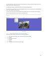
THE SCENE WINDOW .......................................................................................................... 202
THE SCENE WINDOW SETUP .................................................................................................................. 202
6.2
USING THE SCENE OBJECT ..................................................................................................................... 204
6.2.1 OPENING THE SCENE OBJECT WINDOW ............................................................................................. 204
6.2.2 COMPONENTS OF THE SCENE WINDOW............................................................................................. 204
6.2.2.1
THE SCENE WINDOW................................................................................................................. 204
6.2.2.2
SCENE WINDOW SETUP ............................................................................................................. 206
6.2.2.3
MOVING THE ELEMENTS ALONG THE TOOLBAR ......................................................................... 208
6.2.2.4
SCENE TOOLBAR LAYOUTS ......................................................................................................... 209
6.2.2.5
SELECTING THE DISPLAYED CAMERAS ........................................................................................ 209
6.2.2.6
VIDEO IMAGE LAYOUT IN THE SCENE WINDOW ......................................................................... 210
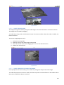
6.2.3 VIDEO IMAGE PROCESSING ................................................................................................................ 211
6.2.3.1
NAVIGATION MODE................................................................................................................... 211
6.2.3.2
IMAGE MOVING MODE ............................................................................................................. 212
6.2.3.3
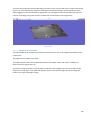
IMAGE PERSPECTIVE CORRECTION MODE .................................................................................. 212
6.2.3.4
IMAGE ROTATION MODE ........................................................................................................... 213
6.2.3.5
IMAGE CROPPING MODE ........................................................................................................... 214
6.2.3.6
SCALING THE IMAGE.................................................................................................................. 214
6.2.3.7
RESTORING IMAGE PARAMETERS. CHANGING THE PROPORTIONS ............................................. 215
6.2.4 USING THE VIDEO ARCHIVE ................................................................................................................ 216
6.2.4.1
ENABLING THE ARCHIVE VIDEO RECORDING PLAYBACK MODE................................................... 216
6.2.4.2
ARCHIVE RECORDING PLAYBACK................................................................................................ 217
6.2.4.3
VIDEO ARCHIVE NAVIGATION .................................................................................................... 218
6
6.2.4.4
6.2.4.5
7
DATE AND TIME OF THE DISPLAYED RECORDINGS ...................................................................... 219
SEARCHING THE RECORDINGS IN THE ARCHIVE BY TIMESTAMP ................................................. 219
TELEMETRY SUBSYSTEM ................................................................................................... 221
7.1
INTRODUCTION ..................................................................................................................................... 221
7.2
THE SUPPORTED PROTOCOLS ................................................................................................................ 222
7.3
CONNECTING THE PTZ DEVICES ............................................................................................................. 222
7.3.1 PTZ devices setup .............................................................................................................................. 223
7.3.2 PTZ connection diagrams ................................................................................................................... 223
7.3.2.1
Analog cameras of the same protocol ........................................................................................ 223
7.3.2.2
IP-cameras ................................................................................................................................ 224
7.4
PTZ object setup .................................................................................................................................... 224
7.4.1 Line object setup ............................................................................................................................... 225
7.5
Using the PTZ devices ............................................................................................................................ 226
7.5.1 Using the monitor interface to control PTZ cameras ........................................................................... 226
7.5.2 The Telemetry Panel object................................................................................................................ 226
7.5.2.1
Saving and deleting the presets ................................................................................................. 229
7.5.3 Joystick setup for controlling the PTZ cameras ................................................................................... 230
8
AUDIO SUBSYSTEM.............................................................................................................. 232
8.1
GENERAL INFORMATION ....................................................................................................................... 232
8.1.1 The file structure used for storing audio files ...................................................................................... 232
8.2
AUDIO OBJECT SETUP............................................................................................................................ 233
8.2.1 Audio setup for IP-devices.................................................................................................................. 234
8.2.2 Audio subsystem setup in case of using the FS-6c and FS-16(exp) video capture cards ........................ 235
8.2.3 Audio subsystem setup in case of using the FS-5B video capture cards ............................................... 236
8.2.4 Audio subsystem setup in case of using the FS-8 video capture cards ................................................. 237
8.2.5 Audio subsystem setup in case of using standard soundblaster cards ................................................. 238
8.2.6 Microphone object setup ................................................................................................................... 240
8.2.7 Microphone object setup ................................................................................................................... 241
8.3
USING THE AUDIO SUBSYSTEM ............................................................................................................. 243
8.3.1 Synchronous video and audio recording on alarm .............................................................................. 243
8.3.2 Synchronous video and audio recording on operator control .............................................................. 243
8.3.3 Playing an audio recording from the archive....................................................................................... 244
8.3.4 The microphone indicator .................................................................................................................. 245
8.3.5 Real time audio playback ................................................................................................................... 246
8.4
Possible audio setup problems and solutions ........................................................................................ 246
8.4.1 The Audio Wizard utility ..................................................................................................................... 246
9
9.1
THE RAY/RELAY SUBSYSTEM........................................................................................... 247
GENERAL INFORMATION ....................................................................................................................... 247
7
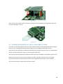
9.2
GENERAL DESCRIPTION OF THE 4/4 RAY/RELAY CARDS......................................................................... 247
9.2.1 Ray/relay cards installation on FS cards .............................................................................................. 248
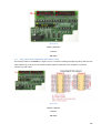
9.3
GENERAL DESCRIPTION OF THE 16/4 RAY/RELAY CARDS ....................................................................... 250
9.3.1 Ray/relay cards installation onto the FS cards..................................................................................... 251
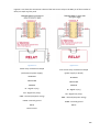
9.4
RAY CONNECTION DIAGRAMS FOR 4/4 AND 16/4 RAY/RELAY CARDS ................................................... 253
9.5
AXXON SMART SETUP FOR USING THE RAY/RELAY CARD ..................................................................... 255
9.5.1 Ray object setup ................................................................................................................................ 255
9.5.2 Relay object setup ............................................................................................................................. 256
9.6
USING THE RAYS/RELAY SUBSYSTEM .................................................................................................... 257
9.6.1 Using the rays .................................................................................................................................... 257
9.6.1.1
Ray icon .................................................................................................................................... 258
9.6.2 Using macros and schedules in the ray/ray subsystem ....................................................................... 259
10
SERVICE MODULES .......................................................................................................... 261
10.1
NOTIFICATION MODULES ...................................................................................................................... 261
10.1.1
Voice notification setup ................................................................................................................. 262
10.1.2
Short Message Service (SMS) ......................................................................................................... 263
10.1.3
Electronic Mail Message Service (E-MAIL) ...................................................................................... 264
10.1.4
Voice Message Service (call) .......................................................................................................... 266
10.2
SYSTEM SECURITY SERVICE.................................................................................................................... 268
10.3
WATCHDOG .......................................................................................................................................... 269
10.3.1
Watchdog setup ............................................................................................................................ 271
10.4
WEB SERVER.......................................................................................................................................... 271
10.4.1
Web Server module setup.............................................................................................................. 273
10.4.2
The home page template ............................................................................................................... 274
10.4.3
Applet parameters......................................................................................................................... 275
10.4.4
Using the browser to operate the web server ................................................................................ 277
10.4.5
Traffic calculation and analysis ....................................................................................................... 279
10.5
POCKET PC............................................................................................................................................. 280
10.6
SMARTPHONE ....................................................................................................................................... 283
11
USER RIGHTS ..................................................................................................................... 288
11.1
GENERAL INFORMATION ....................................................................................................................... 288
11.2
THE USERS TAB...................................................................................................................................... 289
11.2.1
Access rights.................................................................................................................................. 290
11.2.2
Creating a user account ................................................................................................................. 291
11.3
THE RIGHTS TAB .................................................................................................................................... 292
11.4
DEFAULT USER....................................................................................................................................... 293
8
11.5
AUTHORIZATION WINDOW ................................................................................................................... 294
11.6
PASSWORD PROTECTION OF THE VIDEO AND AUDIO ARCHIVE ............................................................. 295
12
POS OPERATIONS CONTROL SUBSYSTEM ................................................................. 296
12.1
GENERAL INFORMATION ....................................................................................................................... 296
12.2
POS TERMINAL CONNECTION SCHEMES ................................................................................................ 297
12.3
POS SUBSYSTEM SETUP ......................................................................................................................... 299
12.3.1
POS object setup ........................................................................................................................... 299
12.3.1.1 Selecting the camera to show the receipt titles over the video image ........................................ 299
12.3.1.2 POS terminal connection setup .................................................................................................. 300
12.3.1.3 Testing POS terminal connection ............................................................................................... 302
12.3.1.4 POS terminal model selection .................................................................................................... 304
12.3.1.5 Recording Mode setup .............................................................................................................. 305
12.3.1.6 Receipt start and end markers setup.......................................................................................... 306
12.3.1.7 Removing the titles from the monitor setup .............................................................................. 308
12.3.2
Titles database setup using the idb.exe utility ................................................................................ 309
12.3.2.1 Using the idb.exe utility ............................................................................................................. 310
12.3.2.2 The Data Link Properties windows ............................................................................................. 311
12.3.3
Titles display setup in the surveillance window .............................................................................. 314
12.3.4
Text Search object setup ................................................................................................................ 316
12.3.5
Showing and hiding the titles in the surveillance window ............................................................... 317
12.4
Using the Titles Search object................................................................................................................ 318
12.4.1
Opening the Titles Search window ................................................................................................. 319
12.4.2
The Titles Search window .............................................................................................................. 319
12.4.3
Creation of a search request .......................................................................................................... 320
12.4.4
The indication of POS terminal connection availability and search process execution ..................... 323
12.4.5
Viewing the list of receipts found in the search .............................................................................. 324
12.4.6
Viewing the receipt contents ......................................................................................................... 325
12.4.7
Viewing the video frame corresponding to the selected receipt line ............................................... 326
12.4.8
Viewing the real time video image from the camera linked to the terminal .................................... 327
12.4.9
Printing and exporting the receipt reports ..................................................................................... 328
13
UTILITIES ........................................................................................................................... 332
13.1
GENERAL INFORMATION ....................................................................................................................... 332
13.2
ARCHIVE CREATION DATE CORRECTION ................................................................................................ 333
13.3
READING THE VIDEO CAPTURE CARD CODES AND HARDWARE PROTECTION KEYS ............................... 334
13.4
Audio subsystem setup wizard .............................................................................................................. 334
13.5
PERFORMANCE MEASUREMENT ........................................................................................................... 335
13.6
DIGITAL SIGNATURE VERIFICATION ....................................................................................................... 337
13.7
ARCHIVE PLAYBACK AND CONVERSION................................................................................................. 339
9
13.7.1
13.7.2
13.7.3
13.7.4
13.7.5
13.7.6
Archive selection ........................................................................................................................... 340
Recordings playback ...................................................................................................................... 341
Searching the archive..................................................................................................................... 342
Exporting frames to BMP or JPG files ............................................................................................. 343
Converting archives to AVI format ................................................................................................. 345
The utility setup............................................................................................................................. 348
13.8
TWEAKING UTILITY ................................................................................................................................ 350
13.8.1
Windows section ........................................................................................................................... 351
13.8.2
The video section........................................................................................................................... 352
13.8.3
The PTZ section ............................................................................................................................. 354
13.9
COLLECTING THE VIDEOSERVER CONFIGURATION AND STATUS INFORMATION FOR TECHNICAL SUPPORT
SERVICE ............................................................................................................................................................. 355
14
REMOTE WORKSTATION SETUP.................................................................................. 356
14.1
GENERAL INFORMATION ON REMOTE WORKSTATIONS ........................................................................ 356
14.2
VIDEOSERVER CONNECTION SETUP ....................................................................................................... 356
14.2.1
Connection creation ...................................................................................................................... 357
14.2.2
Deleting connections ..................................................................................................................... 358
14.2.3
Connection setup .......................................................................................................................... 359
14.3
USING THE REMOTE WORKSTATION ..................................................................................................... 361
14.3.1
Connecting to several servers ........................................................................................................ 361
15
POSSIBLE PROBLEMS IN USING AXXON SMART ...................................................... 362
15.1
POSSIBLE AXXON SMART STARTUP PROBLEMS ..................................................................................... 362
15.1.1
Card or guardant driver not loaded ................................................................................................ 362
15.1.2
Key not found ................................................................................................................................ 363
15.1.3
Key does not match the card.......................................................................................................... 363
15.2
POSSIBLE PROBLEMS IN THE VIDEO CAPTURE CARD INSTALLATION AND SETUP ................................... 363
15.2.1
Codereader.exe cannot read the card codes .................................................................................. 363
15.2.2
Windows 2000 cannot recognize new hardware ............................................................................ 365
15.2.3
Corrupted video image .................................................................................................................. 366
15.2.4
Two cameras send the same image, or some cameras send no image ............................................ 366
15.3
Possible problems in IP-devices setup ................................................................................................... 366
15.4
POSSIBLE PROBLEMS IN AUDIO SUBSYSTEM SETUP .............................................................................. 367
15.4.1
Audio Wizard Utility....................................................................................................................... 367
16
INDEX .................................................................................................................................. 368
10
1 AXXON SMART INSTALLATION, UPDATING AND REMOVAL
1.1 LICENSING METHOD
Licensing is used to set the conditions for and regulate the usage of AXXON SMARTsoftware modules.
The Axxon Smart software is licensed using the video.sec key file, which links the AXXON
SMARThardware protection to the software modules. The key file is included in the software installation
package and regulates the functionality (configuration) of the system.
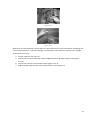
The dallas codes of the video capture card cryptochips (FS-5B, FS-6C, FS-8, FS-16(Exp), WS-7, WS-17)
and/or the dallas code of the Guardant electronic hardware protection key form the hardware side of
the AXXON SMARTprotection.
The Card Code Reader utility is used for reading the dallas codes from the video capture card cryptochip
or the Guardant hardware protection key. The utility displays the codes in the Code Reader window.
The Axxon Smart software comprises of several modules. Each module is represented by an executable
file.
The list of available functional software modules depends on the delivery configuration of the system
and is included in the video.sec key file.
When extending the system configuration (for example, in case of installing a new functional
subsystem), the key file should be replaced with a new one to activate the newly installed module.
IMPORTANT! When a video capture card is replaced, its dallas codes change accordingly. Thus, the key
file should be replaced with a new one. In a distributed system, key files on all computers should be
replaced.
IMPORTANT! If the video capture cards manufactured by AXXON are used in the video server, then
connecting the Guardant hardware protection key will make starting the Axxon Smart system
impossible.
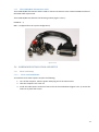
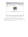
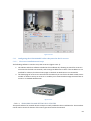
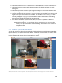
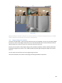
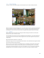
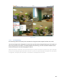
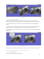
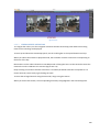
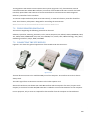
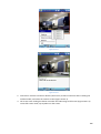
1.2 THE AXXON SMART INSTALLATION KIT
The Axxon Smart software is delivered in the form of an installation CD (Figure 1.2.1-1). The installation
disk contains all the software components required to install Axxon Smart on the computer.
11
Figure 1.2.1-1
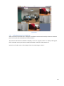
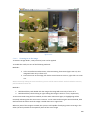
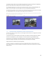
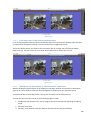
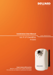
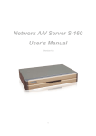
1.2.1 Drivers
You will always find all the required drivers in the Drivers folder of the Axxon Smart installation CD.
During the installation, all the drivers necessary for the chosen configuration are copied and registered
in the C:\Windows\Drivers system folder (Figure 1.2.1-1).
Figure 1.2.1-1
12
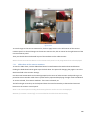
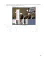
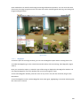
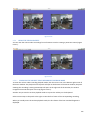
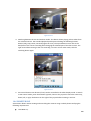
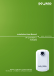
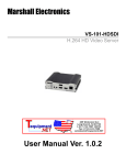
1.2.2
Key file
Figure 1.2.2-1
The video.sec key file is required for activating the software. The key file is included in the installation kit
and is located in the Key folder of the installation CD. The key file determines the configuration of the
Axxon Smart instance to be installed (Figure 1.2.2-1).
NOTE. Axxon Smart will not work without the key file! If the key file is lost or unavailable, contact your
AXXON dealer.
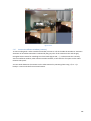
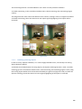
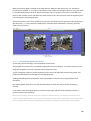
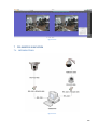
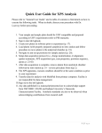
1.2.3 Additional components
The Redist folder of the installation package contains the required additional programs and components
(Figure 1.2.3-1):
Net2.0 - Microsoft .NET Framework 2.0 – the required system component;
SQLExpress - Microsoft SQL Server Express 2005 – the database management system for managing the
Axxon Smart databases;
MSDE - Microsoft Data Engine – the program for database creation and maintenance;
Java – the J2SE 5.0 Update 6 installation package.
Active Sync- Microsoft ActiveSync is a software release for Windows Mobile-based devices. ActiveSync
provides a great synchronization experience with Windows®-based PCs and Microsoft Outlook right out
of the box. ActiveSync acts as the gateway between your Windows-based PC and Windows Mobilebased device, enabling the transfer of Outlook information, Office documents, pictures, music, videos
and applications to and from your device. In addition to synchronizing with a desktop PC, ActiveSync can
13
synchronize directly with Microsoft Exchange Server 2003 so that you can keep your e-mail, calendar
data, tasks and contact information updated wirelessly when you’re away from your PC.
IPP- Intel® Integrated Performance Primitives (Intel® IPP) library has the majority of optimised functions
compatible with systems on the multi-core processor base and targeted for multimedia, data processing
and communication application.s
VC2005_SP1-The Microsoft Visual C++ 2005 SP1 Redistributable Package (x86) installs runtime
components of Visual C++ Libraries required to run applications developed with Visual C++ on a
computer that does not have Visual C++ 2005 installed.
Windows Installer-The Microsoft® Windows® Installer is an application installation and configuration
service. WindowsInstaller-KB893803-v2-x86.exe is the redistributable package for installing or upgrading
Windows Installer. This revised package replaces the previously released redistributable package named
"WindowsInstaller-KB893803-x86.exe" and addresses the issue discussed in KB Article 898628: Windows
Installer fails silently after you upgrade to Windows Installer 3.1.
Figure 1.2.3-1
1.3 AXXON SMART INSTALLATION
You must have Windows administrator rights to install the Axxon Smart software (Figure 1.2.3-1).
14
Figure 1.2.3-1
This section contains the step-by-step procedure for installing the Axxon Smart software.
Axxon Smart is installed in two stages: first, the basic Axxon Smart version is installed, then, the Axxon
Smart v.1.0.0 SP3 update pack, which is included in the installation disk, starts after a couple of seconds.
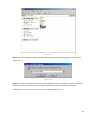
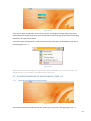
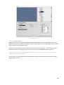
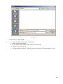
Step 1. Insert the Axxon Smart installation disk in the CD-ROM drive and open it in a separate window of
your computer. To start the installation process, run the setup.exe file (Figure 1.2.3-1). It is located in the
root folder of the installation disk (Figure 1.2.3-2).
15
Figure 1.2.3-2
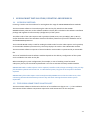
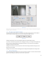
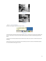
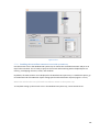
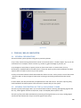
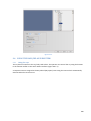
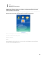
Step 2. Choose installation language dialog window will open.Select the language and click Ok button
(Figure 1.2.3-3).
Figure 1.2.3-3
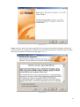
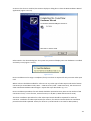
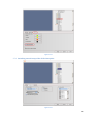
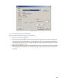
Step 3. The welcome dialog screen will open. The installation process is interactive. Please, monitor the
installation process closely and enter the required information when prompted by the wizard.
Click Next to continue. Click Cancel to cancel the installation (Figure 1.2.3-4).
16
Figure 1.2.3-4
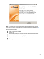
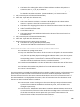
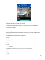
Step 4. Accept or decline the licensing agreement for using the Axxon Smart technology. Click Print to
print out the text of the agreement. Familiarize yourself with the agreement conditions, then click Next,
otherwise the software installation will quit (Figure 1.2.3-5).
Figure 1.2.3-5
17
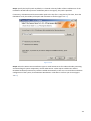
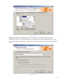
Step 5. Specify the key file path. By default, it is located in the Key folder of the installation CD. If the
installation wizard finds a previous installation path in the registry, this path is specified.
If necessary, click Browse and choose another path to the key file. To copy the key file later, leave the
field blank. Verify the validity of the path and click Next to confirm (Figure 1.2.3-6).
Figure 1.2.3-6
Step 6. Select the Axxon Smart installation type. To install Axxon Smart for video and audio processing
and controlling all system components, choose Video Server. Video capture card drivers and the
Guardant hardware protection key will be installed automatically in this case. To install the workstation
configuration of the system, choose Remote Workstation. Click Next to confirm your choice (Figure
1.2.3-7).
18
Figure 1.2.3-7
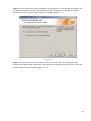
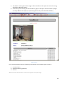
Step 7. Installation of license key file window will open (Figure 1.2.3-8).Enter your Axxon Smart
v.1.0.1.470 license key and click Next to continue.
Figure 1.2.3-8
19
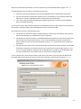
Step 8. You may choose Full or Custom installation. If you select Full, all Axxon Smart components will
be installed. If you select Custom, a dialog window will open at the next step allowing to select the
components to install. Confirm your choice by clicking Next (Figure 1.2.3-9).
Figure 1.2.3-9
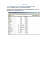
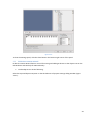
Step 9. If you have chosen Custom installation in the previous step, select the components to be
installed. To include/exclude a component, check/uncheck the checkbox next to it in the list. Check the
required components and click Next (Figure 1.2.3-10).
20
Figure 1.2.3-10
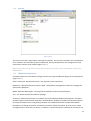
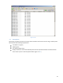
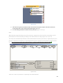
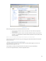
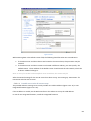
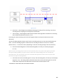
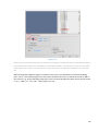
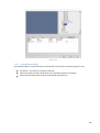
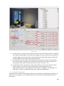
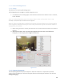
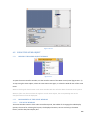
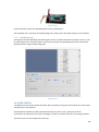
Step 10. Select a Microsoft SQL database server and authorization method and parameters for
connecting to the server. Use the Database Server drop-down list to select the MS SQL server. To use
the server located on this computer, leave the "local" value which appears in the field by default (Figure
1.2.3-11).
Figure 1.2.3-11
21
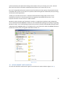
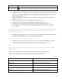
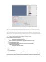
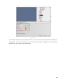
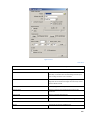
Select the authorization parameters to connect Axxon Smart to the MS SQL Server (Figure 1.2.3-12).
The following data may be used for connecting to the server:
1. The user name and password used to install the MS SQL Server in Axxon Smart installation.
2. Account information entered when registering users in Windows on the computer where MS
SQL Server is located, if Windows Account was selected for authorization.
3. User names and passwords specified when registering accounts in a fully-functional MS SQL
Server (installed separately).
To use the user name and password specified in the Windows account on the computer onto which the
Axxon Smart is being installed, select the Windows Account connection mode.
This mode can be chosen in the following cases:
1. The SQL Server from Axxon Smart installation disk (or a third-party manufacturer disk) and the
Axxon Smart software are installed on the same computer.
2. The SQL Server and Axxon Smart are installed on different computers connected via TCP/IP and
are located in the same network domain. In this case, the MS SQL computer and the Axxon
Smart computer must have the same Windows accounts, i.e. e. with identical user names and
passwords.
3. The fully-functional SQL Server (installed separately) and the Axxon Smart software are installed
on different computers connected via TCP/IP and located in the same network domain. In this
case, an account should be created on the remote SQL Server computer for the Windows user
currently authorized on the computer where Axxon Smart is being installed.
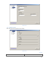
To use a specific user name and password for SQL Server connection, select the Use User Name and
Password radio-button and enter the user name and password in the fields below (Figure 1.2.3-12).
Figure 1.2.3-12
22
This mode of connection is available in the following cases:
1. The SQL Server from the Axxon Smart installation disk and the Axxon Smart software are
installed on the same computer. Then, you can connect to the SQL Server with this user name
and password from any remote computer located in the same TCP/IP network domain as the
SQL Server computer.
2. The SQL Server from the Axxon Smart disk and Axxon Smart are installed on different computers
connected via TCP/IP and are located in the same network domain. Then, the user name and
password specified here should match the user name and password used to access the SQL
Server.
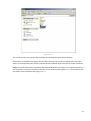
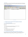
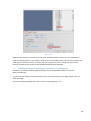
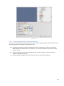
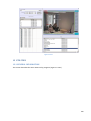
Step 11. The files are being copied into the Axxon Smart program folder. Wait until the process is
finished. To cancel the installation, click Cancel (Figure 1.2.3-13).
Figure 1.2.3-13
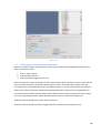
Step 12. After all files are copied, the installation wizard will inform you that the Axxon Smart
installation is complete. To confirm, click Finish (Figure 1.2.3-14).
23
Figure 1.2.3-14
1.4 AXXON SMART REMOVAL
To uninstall Axxon Smart, follow the procedure below:
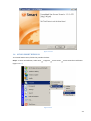
Step 1. To start uninstallation, select Start
(Figure 1.2.3-1).
Programs
Axxon Smart
Axxon Smart de-installaztion
Figure 1.2.3-1
24
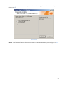
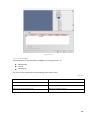
Step 2. Specify Axxon Smart v.1.0.0.106 program de-installation type, choosing the Remove all option
(Figure 1.2.3-2).
Figure 1.2.3-2
Step 3. Press “Remove” button to begin Axxon Smart v.1.0.0.106 uninstallation process. (Figure 1.2.3-3).
25
Figure 1.2.3-3
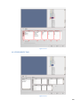
Step 4. Axxon Smart uninstallation process is running (Figure 1.2.3-4). Press “Cancel” button to end the
procedure.
Figure 1.2.3-4
Step 5. To confirm the uninstallation and quit the wizard, click Finish (Figure 1.2.3-5).
26
Figure 1.2.3-5
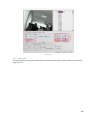
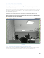
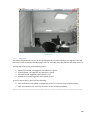
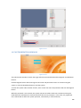
Step 6. To completely delete the Axxon Smart software from your computer, manually delete the
/Axxon Smart program folder and all /Video folders created for video archive storage (Figure 1.2.3-6).
The Axxon Smart folder contains:
current version of the titles database;
license key file;
folders with the video recordings and frames exported in the course of using Axxon Smart;
Axxon Smart configuration file and its backup copy;
After the first launch of the Axxon Smart system, the video.cfg file is created containing
information about all system objects.
log files containing the information about operation of Axxon Smart modules;
backup copies of these files.
27
Figure 1.2.3-6
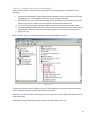
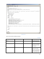
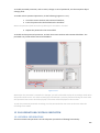
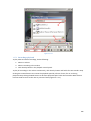
Step 7. Finally, delete the registry branch related to Axxon Smart: HKEY_LOCAL_MACHINE
\SOFTWARE\AXXON SMART (Figure 1.2.3-7).
28
Figure 1.2.3-7
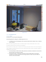
1.5 THE CONTENTS OF THE AXXON SMART PROGRAM FOLDER
This section describes the contents of the Axxon Smart program folder.
The video.exe module is the core of the Axxon Smart software. Other modules (ex., audio or PTZ
subsystems) connect to this module (Figure 1.2.3-1).
Figure 1.2.3-1
1.5.1 Databases (data)
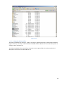
The C:\Program Files\Microsoft SQL Server\MSSQL.1\MSSQL\Data (Figure 1.5.1-1).
29
Figure 1.5.1-1
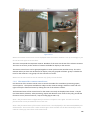
1.5.2 User manual (manual)
The Manual folder contains the documentation for Axxon Smart (Figure 1.5.2-1).
Figure 1.5.2-1
30
1.5.3 Modules (modules)
Several connectable modules form the software structure of the system. Each module is represented by
an executable file. The video.exe module runs other modules’ executables when necessary. All software
modules are located in the Modules folder (Figure 1.5.3-1).
Figure 1.5.3-1
1.5.4 Utilities (tools)
All system utilities are located in the Tools folder. The utilities will be described in detail later (Figure
1.5.4-1).
31
Figure 1.5.4-1
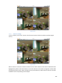
1.5.5
Voice notification files (*.WAV)
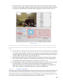
Voice notification is one of the ways to inform the operator about alarm’s registration in the system.
Voice notification files are located in the Wav folder that is automatically installed when Axxon Smart
software is being installed (Figure 1.5.5-1 ).The user of the system with administrator rights can change
voice notification files for other audio files of wav format. Indispensable condition is to create the name
of new file by mask [cam_alarm_x].wav, so that x is the number of camera for which this audio file is
used.
32
Figure 1.5.5-1
1.5.6 Smartphone
Axxon Smart provides the option of remote video surveillance and camera control using a mobile phone
which satisfies the following requirements:
Java MIDP 2.0 support;
GPRS support;
color display (65K colors);
display resolution not less than 100х100 pixels and the specialized software included with the
Axxon Smart system in the Smartphone folder (Figure 1.5.6-1).
33
Figure 1.5.6-1
1.5.7 Smartppc
Axxon Smart provides the option of remote video surveillance and camera control using the PocketPC
computer. To use this option, you need a PocketPC that supports any available technology for network
access and the specialized software included equipped with Axxon Smart and located in the SmartPPC
folder (Figure 1.5.7-1).
Figure 1.5.7-1
34
1.5.8 Iface
This folder contains the resource dll file which holds the information about the color schemes for the
Scene and Monitor interface objects. These files are required for system operation, so its modification
or deletion is forbidden (Figure 1.5.8-1).
Figure 1.5.8-1
2 STARTING AND CLOSING THE AXXON SMART SOFTWARE
2.1 GENERAL INFORMATION
There are several ways to start the Axxon Smart system:
Manual start
from the Start menu, Programs submenu, in the Windows taskbar;
using the Axxon Smart shortcut on the desktop .
Automatic start
by placing the shortcut in the Startup menu;
instead of the Windows standard shell;
by installing Axxon Smart as a service.
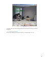
2.2 STARTING AXXON SMART FROM THE WINDOWS START MENU
Generally, Axxon Smart is started from the Windows taskbar. Click the Start button and select the
following menu sequence: Start Programs Axxon Smart Axxon Smart (Figure 1.5.8-1).
35
Figure 1.5.8-1
2.3 AUTOMATIC START
2.3.1 AXXON SMART in the Startup menu
To start Axxon Smart automatically, manually create a shortcut of the video.exe file in the Axxon Smart
program folder and move it to the Startup item of the Start Programs menu (Figure 2.3.1-1).
Figure 2.3.1-1
2.3.2
Automatic start of AXXON SMART on computer power-on instead of the standard
Windows shell
To restrict the use of normal functionality of the computer, i.e. starting of other applications, copying
and deleting files, etc, set up the Axxon Smart software to start on computer power-on instead of the
standard Windows shell.
36
Axxon Smart will start immediately after Windows has loaded instead of the Explorer program. Thus, the
user will not be able to run other installed applications and use dialog windows. To set up Axxon Smart
to start instead of the Windows shell, some registry parameters should be modified. To edit the registry,
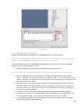
use the TweakiAxxon Smart.exe utility.
Start the utility from the Tools folder of the Axxon Smart program folder (ex. C:\Axxon Smart\Tools), or
from the Windows Start menu (Start Programs Axxon Smart Utilities Tweaking utility (Figure
2.3.2-1). In the TweakiAxxon Smart dialog window, open the Windows section and set the Shell group to
File option. To start Axxon Smart in the Video Server configuration, specify the full pathname of the
video.exe file into the field in the Shell group. Type the filename and pathname in manually, or use the
Browse button to locate the file.
The TweakiAxxon Smart.exe utility does not allow setting up Axxon Smart to start instead of the shell in
the Workstation configuration.
Figure 2.3.2-1
2.3.2.1 Setting up Windows to start with no password authorization
If user authorization is required at Windows start-up (e.g. in case of several user accounts), the default
user Windows start-up should be set for automatic Axxon Smart start-up instead of the shell. Some
registry parameters should be changed using the TweakiAxxon Smart.exe utility.
Start the utility from the Tools folder of the Axxon Smart program folder (e.g. C:\Axxon Smart\Tools), or
from the Windows Start menu. In the Windows section, in the Autolog group, enable automatic
authorization mode by checking the Enable checkbox and entering the default user name and password
in the corresponding fields which will be used for automatic authorization (Figure 2.3.2-2).
37
Figure 2.3.2-2
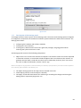
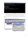
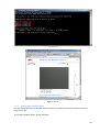
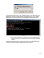
2.3.2.2 Forced start of Explorer
To manually start Explorer, open the Task Manager window (press Ctrl+Shift+Esc). Select menu File,
then New Task (Run). In the dialog box that opens, type "explorer" and click OK (Figure 2.3.2-3).
38
Figure 2.3.2-3
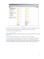
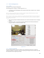
2.3.3 Start AXXON SMART as a service
Another way of using the Axxon Smart software is by running it as a Windows service.
Service functionality allows creating executable applications that work continually as separate Windows
sessions. The services may have no interface elements and may be started on computer power-on,
closed at will and started again.
This allows using the services on the server or other computers with no user interaction. Besides, the
service can be started in the security context different from the current Windows user, or in the security
context of another user, or the default user of the computer.
To install Axxon Smart as a service, check the Install Axxon Smart as a Service checkbox in one of the
installation wizard windows at the time of system installation.
When Axxon Smart runs as a service, the system is entered under the system user only.
The name of the created service: Axxon Smart.
The description of the created service: Runs video.exe as a Windows service
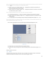
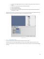
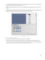
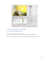
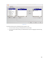
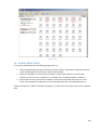
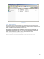
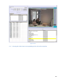
To set up, start and stop the services, use the Computer Management window which can be opened by
right-clicking the My Computer icon on the Desktop and selecting Manage in the context menu. View
and edit all existing services on the computer in the Services and Applications tab. To modify, enter the
properties of the required service.
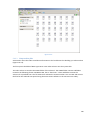
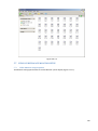
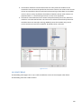
A service can be started manually or automatically by selecting the corresponding options. If the service
fails, response actions can be set (ex., service re-start, application start, computer re-start), to restore
the service (Figure 2.3.3-1).
39
Figure 2.3.3-1
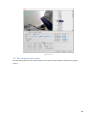
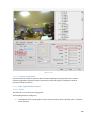
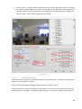
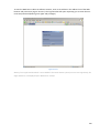
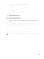
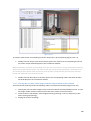
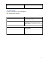
2.4 Closing AXXON SMART
To close the Axxon Smart software, point the cursor to the top right corner of the screen to open the
Main control panel, click the Run (arrow down) button on the panel and select Shut Down in the dropdown menu (Figure 2.3.3-1).
Figure 2.3.3-1
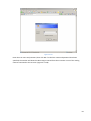
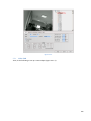
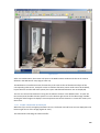
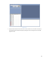
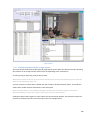
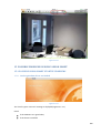
The user authorization request window will open (Figure 2.3.3-2).
40
Figure 2.3.3-2
If the access rights management is used in the system, and program settings require password
authorization on closing the system, enter the password. After entering the password and clicking
Shutdown, the system shuts down.
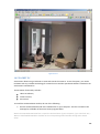
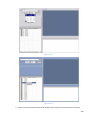
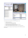
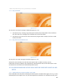
If no access rights management is used, the system shuts down after the Shutdown menu item is
selected (Figure 2.3.3-3).
Figure 2.3.3-3
NOTE: If the rights and privileges settings in Axxon Smart forbid the user to close the system, the
Shutdown item is not included in the Main control panel menu.
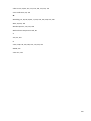
2.5 POSSIBLE PROBLEMS AT AXXON SMART START-UP
2.5.1
Cards or guardant drivers not loaded
Figure 2.5.1-1
The startup information window shows the “Card’s type is incorrect” message (Figure 2.5.1-1).
41
Check:
if the hardware is in good order;
if the driver is installed.
NOTE: The problem may occur if an old driver is installed.
2.5.2
Key not found
Figure 2.5.2-1
The startup information window shows the “Key file is not found” message (Figure 2.5.2-1).
The video.sec key file is missing. Copy the key file manually from the Key folder of the installation CD
into the Axxon Smart program folder. If there is no key file in the installation CD, contact the dealer.
The video.sec key file exists in the Axxon Smart program folder. The file is probably invalid. Contact the
dealer.
2.5.3
Key doesn’t match the card
Figure 2.5.3-1
The startup information window shows the “Key file is not valid” message (Figure 2.5.3-1).
The key file exists but does not match the video capture card(s). To obtain a new key file, use the
Codereader.exe utility for reading the card codes included in the Axxon Smart delivery kit. Using this
utility, read the dallas codes of the card(s) (a set of alphanumeric strings) and send them to the dealer
together with a description of the problem.
42
3 BASIC PRINCINPLES OF THE USER INTERFACE
3.1 MAIN CONTROL PANEL
To show the Axxon Smart Main control panel, point the cursor to the top right corner of the screen.
The Main control panel is a small interface panel containing the information box, the Interface Menu
button and the Run button (Figure 2.5.3-1).
Figure 2.5.3-1
The information (tips) box displays the error messages.
The Interface Menu button allows starting and closing the user monitors, the Scene object, PTZ control
windows, POS-operations video control windows, as well as starting the Moment Quest module.
The Run button allows opening the System Settings window, closing the session by an authorized user,
new user authorization and system shut down.
To hide the Main control panel, move the cursor away from it.
3.2 STARTING AND CLOSING THE USER INTERFACE
The Axxon Smart user interface comprises of the Monitor, the PTZ and the POS. Up to 4 video
surveillance monitors are available to an operator. The system settings determine which Monitor
objects are available. To open or close an interface window, use the Interface Menu button in the Main
control panel. The Interface menu that opens contains the list of Monitor objects and their interface
objects (PTZ, POS).
To open an interface window, click the Interface Menu button, then select the required Monitor in the
list. The selected object in the list will be indicated by the dot inside the circle.
To open several Monitors repeat the procedure for each of them. To close a user window, click the
Interface Menu button, then select the required Monitor in the list.
To close all interface windows, click the Hide All item in the Interface Menu (Figure 2.5.3-1).
43
Figure 2.5.3-1
NOTE: If the system rights are set up to forbid the user from closing the interface windows, the Hide All
item is disabled.
3.3 THE AXXON SMART SETTINGS PANEL
3.3.1 General information
To manage the Axxon Smart system, use the Settings panel. The Axxon Smart Settings panel is designed
to configure the components of the video surveillance system based on the Axxon Smart software. The
Settings panel allows:
a. configuring the hardware and software modules;
b. setting up the user interface;
c. creating users, administration of the user rights and privileges, assigning passwords for
accessing the system resources by users;
d. IP devices creation wizard.
3.3.2 Opening and closing the Settings panel
To open the Settings panel, click the Run button in the Main control panel (Figure 3.3.2-1)
Figure 3.3.2-1
And select System Settings in the drop-down menu (Figure 3.3.2-2).
44
Figure 3.3.2-2
To close the Settings panel, click the Close button in the bottom right corner of the panel.
3.3.3 IP devices creation wizard
IP devices creation Wizard function is used for searcing and adding IP devices to the objects tree on the
tab Hardware with the help of IP Wizard utility.
1. To edit objects tree do the following:
Select the required object Computer on the tab hardware of Sysytem settings dialog window (Figure
3.3.3-1).
45
Figure 3.3.3-1
2. Click with the right mouse button upon the selected Computer object and select IP Devices
creation Wizard in the contextual window (Figure 3.3.3-1).
3. In result dialog window of IP Wizard utility will open (Figure 3.3.3-2).
Note.
When started IP Wizard utility searces for IP-devices, registered in the PC Intellect. Parameters of the
found devices will be accessible for editing in the table IP devices utility (Figure 3.3.3-2, 6-12).
The utility also automatically indicates connected hardware.The list of the devices, supporting the given
function is shown in the Table 3.3-1. All integrated IP cameras support manual adding of objects to the
tree - http://www.axxonsoft.com/products/axxon_professional/integration/cameras.php
Figure 3.3.3-2
Table 3.3-1 The list of IP devices, supporting auto determination.
46
Table 3.3-1
Brand of IP device
Beward
Model of IP device
B-915
B-970
B-975
JVC all models
all models–
http://www.axxonsoft.com/products/axxon_professional/integration/cameras.php
Panasonic
all models –
http://www.axxonsoft.com/products/axxon_professional/integration/cameras.php
Samsung
SNC-B5395
SNC-B2315
SNC-M300
TrendNet
all models –
http://www.axxonsoft.com/products/axxon_professional/integration/cameras.php
Arecont
all models -
http://www.axxonsoft.com/products/axxon_professional/integration/cameras.php
MicroDigital
all models –
http://www.axxonsoft.com/products/axxon_professional/integration/cameras.php
Pixeye
all models –
http://www.axxonsoft.com/products/axxon_professional/integration/cameras.php
StarDot
NetCam SC 1.3 MP IR
D-Link
DCS-6620G
DCS-5220
DCS-3420
DCS-3220G
Vivotek
IP6122
Sony
all models http://www.axxonsoft.com/products/axxon_professional/integration/cameras.php
Axis
All models, except versions with firmware less than 4 cm.http://www.axxonsoft.com/products/axxon_professional/integration/cameras.php
47
Brand of IP device
Model of IP device
4. Setting parameters of IP device, that has to be added to the objects tree on the tab Hardware is
performed in the group Add device manually.IP address of the required device is set in the fielf
IP address (Figure 3.3.3-2, 1).
5. When necessarychange port of IP device’s connection to the server Intellect in the field Port
(Figure 3.3.3-2, 2).
6. Select the brand of IP device from the dropdown list (Figure 3.3.3-2, 3).
7. Select the name of IP device from the dropdown list Model (Figure 3.3.3-2, 4).
8. To add IP device to the table IP devices of IP Wizard utility click Add (Figure 3.3.3-2, 5).
9. In result parameters of the required device will be displayed in the table IP devices (Figure
3.3.3-2, 6-12).
Note. To delete IP device from the table the following command order of the contectual menu should be
performed «Delete camera <IP address> from the list» (is called with wright mouse click upon the
corresponding line of the table).
10. In field 6 of the table (Figure 3.3.3-2, 6) brand of IP device is stated. To display the list of objects,
accessible for the following device click«+» on the left of the field.
Note. To hide the list press «-» on the left of the field.
11. To register objects of IP device in the objects tree certain check marks should be set.To delet
objects from the objects tree uncheck the mark in the check box (Figure 3.3.3-2, 6).
Note.
To register/delete all the objects it is enough to check/uncheck the mark in the check box opposite the
brand of IP device.
Object names in «IР Wizard» correspond to the branch of the objects tree (Table 3.3-2).
Table 3.3-2 Соrrespondance of «IP Wizard» objects to brances of objects tree
Table 3.3-2
Object name in «IP Wizard»
Branch of objects tree PC«Intellect»
Video channel
Оbject «Video capture card» > Оbject «Camera»
Audio channel
Оbject «Sound card» > Оbject «Microphone»
Contact
Object«Video capture card» > Оbject «Sensor»
Executive device
Object«Video capture card» > Object«Relay»
PTZ line
Object «PTZ control» > Object «PTZ device»
12. In the field 7 of the table (Figure 3.3.3-2, 7) state name of the model of IP device.
48
Note. To change brand and model in the table of IP device dropdown lists should be used (are called with
the click of
button on the right of the corresponding column).
13. When necessary in the field 8 of Figure 3.3.3-2 change the user name for connection to IPdevice (on default factory name is stated).
14. When necessary in the field 9 of Figure 3.3.3-2 change the password for connection to IP-device
(on default factory name is stated).
Note. To display password set the cursor in any place of the given password.
15. In the field 10 of Figure 3.3.3-2 device’s Ip address is displayed (unaccessible for editing).
16. When necessary in the field 11 of Figure 3.3.3-2 change the connection ort of IP device to the
Intellect Server.
17. To change objects tree according to the given settings click Apply button (Figure 3.3.3-2, 12).
Note. Number of objects, accessible for adding to the tab Hardware are automatically displayed in the
table Availiable hardware (Figure 3.3.3-2, 13).
18. In result in the objects tree the required changes will be displayed (Figure 3.3.3-3).
Figure 3.3.3-3
19. Repeat step 4-17 to add and edit all the required IP devices.
20. To close the utility processing and «IP Wizard» dialog window click Exit button (Figure 3.3.3-2,
14).
Editing of objects tree is over
3.3.4 About
Clicking the About program item of the Run menu in the Main control panel to open an information
window which displays the software version and card codes (Figure 3.3.4-1).
49
Figure 3.3.4-1
3.3.5 Description of the Settings panel
To manage the Axxon Smart system, use the Settings panel. The Axxon Smart Settings panel is designed
to configure the components of the video surveillance system based on the Axxon Smart software. The
Settings panel allows:
1. configuring the hardware and software modules;
2. setting up the user interface;
3. creating users, administration of the user rights and privileges, assigning passwords for
accessing the system resources to users.
The Settings panel consists of the following components:
1. Object tree. This is a multi-level nested list of objects. The branches of the tree can be expanded
to view their contents, or contracted to hide the objects that are irrelevant at the moment. To
go down one level from a node and view the list of its child nodes, click the “plus” icon next to
the node. To hide all child nodes, click the “minus” sign.
NOTE: The objects configuration is determined by the delivery specification of the Axxon Smart software
set in the key file included in the delivery set.
2. The object settings panel for the object that is selected in the tree.
3. Video display panel (if a Camera object is selected).
4. The Apply, Cancel and Close buttons for confirming or canceling the changes and closing the
Settings panel, respectively (Figure 3.3.5-1).
50
Figure 3.3.5-1
NOTE: When the Settings panel initially opens, the Computer object settings are displayed, though the
Computer object is not selecte.
3.3.6 The Apply, Cancel and Close buttons
The Apply, Cancel and Close buttons at the bottom of the object settings panel are used to apply or
cancel the object settings changes, and to close the Settings panel (Figure 3.3.6-1).
Figure 3.3.6-1
Clicking the Apply button saves and immediately applies the specified object settings.
If you have not clicked the Apply button after changing the settings, your changes will be applied only
after you close the Settings panel by clicking the Close button, in case you have not canceled the
changes by clicking the Cancel button.
Clicking the Cancel button restores the previous values of the settings (set before the Apply or Close
buttons were last clicked).
Clicking the Close button closes the Settings panel. All changes will be applied to the settings values.
3.3.7 Object Settings panel
The object settings panel is designed to set up the parameters of objects. It contains various functional
groups of fields designed to specify the certain values to parameters.
51
The object panel may contain tabs. The tab titles are located at the top left corner of the panel. Table
3.3-3 describes the interface elements used in the object settings panels.
Table 3.3-3
Element image
Element name
Element description
Numerical parameter
entry field
Enter the numerical value
String parameter entry
field
Enter the string value
Checkbox
Check/uncheck
Radio-button
Select one of the options
Slider
Drag the slider in the desired
position to set the value of
the parameter.
Drop-down list
Select an item
Table
Data entry:
1. Check the checkbox in the
left column.
2. Enter/select the values in
other columns of the
selected row.
3. To remove a row, uncheck
52
its checkbox.
4 MACROS AND SCHEDULES
4.1 CREATING AND USING THE MACROS
A macro in Axxon Smart is a system object design for describing logic interactions among other system
objects. A macro makes an object automatically execute a user specified action upon occurrence of an
event on the object selected in the Axxon Smart list.
To create, modify or delete macros, select the Macros object in the object tree of the Settings panel.
Figure 3.3.7-1
To create a macro, do the following (Figure 3.3.7-1):
1. Enable macro execution. To save the macro parameters and enable macro execution,
check the checkbox in the left column of the settings table.
To disable and remove the macro, uncheck the checkbox.
NOTE: A disabled (unchecked) macro is not saved in Axxon Smart.
2. In the Device drop-down list, select which object’s event should trigger macro
execution. It can be a specific camera, detection zone, ray or All Cameras (All Rays, All
Zones) value. In the latter case, the macro will execute upon event registration on any
object of the specified type.
53
3. In the Event drop-down list, select which event should trigger macro execution.
Different sets of events are available for different object types.
4. In the Device drop-down list, select the object to receive the action upon registration of
the specified event. It can be a specific camera, detection zone, ray, relay, or Application
or All Cameras (All Rays, All Zones, All Relays) value. In the latter case, the action will
apply to all objects of the specified type.
The Application value indicates that a specific application should be launched upon registering the
specified event. If the Application option is selected, the full path and file name of the application should
be specified in the Action column.
5. In the Action drop-down list, select an action to be applied to the specified object.
Different sets of actions are available for different object types.
6. In the Delay column, set the delay time (in seconds) between the event registration and
macro execution. By default (if no value is set in the Delay column), the delay is 0, that is
the action executes immediately. Macros are executed in pairs, where the first
command starts the process and the second command completes it.
NOTE: A sequence of macros cannot be created in Axxon Smart.
4.2 CREATING A SCHEDULE
Schedules are used for automatic execution of a specified action by a specified object when a specified
date and time are reached.
To create, modify or delete schedules, use the Schedule object in the object tree of the Settings panel.
To add commands to a schedule, do the following (Figure 3.3.7-1):
1. Enable execution of an action. To enable execution of an action, check the checkbox in
the left column of its row in the settings table. To disable an action, uncheck the
checkbox.
2. Specify the action execution date. To specify the date, enter the values in the Month,
Day, and Day of the Week columns. An action can be set up for any month, any day or
any day of the week. Enter specific values in the columns. If an action should execute
each month, each day, or each day of the week, enter Any in the corresponding
columns.
NOTE 1: To set up an action to be executed every day at a specified time, enter Any in the Month, Day
and Day of the Week fields.
NOTE 2: Specific Day and Day of the Week values cannot be set simultaneously, because these
parameters are interdependent. If one of them is specified, the other is automatically set to Any.
3. Specify the action execution time. To specify the execution time, enter the value in the
Time column. Use the following format – HH:MM:SS, where HH – hours, MM – minutes,
SS – seconds. By default, the parameter is set to 00:00:00 which means the action
executes at midnight.
4. Specify the object to apply the action to. Enter the value in the Device column. It can be
a specific camera, detection zone, ray, relay or All Cameras (All Rays, All Zones, All
Relays) value. In the latter case, the action will apply to all object of the specified type.
54
5. Specify the action to execute. Enter the value in the Action column. The available
actions depend on the device type specified in the Device column.
Figure 3.3.7-1
5 VIDEO SUBSYSTEM
5.1 GENERAL INFORMATION
The video surveillance subsystem of the Axxon Smart system includes all video surveillance functions:
1.
2.
3.
4.
Video image processing;
Video image display;
Video image storing;
Video image transmission.
55
5.2 VIDEO FORMATS
Processing
g
alo
An
o
de
vi
Digitizing
Video flow management
Video transmission (TCP/IP)
Compression of
digitized video
Storage
Figure 3.3.7-1 shows the analog-to-digital conversion and transmission of the signal.
Processing
g
alo
An
o
de
vi
Digitizing
Video flow management
Video transmission (TCP/IP)
Compression of
digitized video
Storage
Figure 3.3.7-1
Two basic TV formats exist today: NTSC and PAL.
The NTSC (National Television System Color) analog format was developed in the USA. This format is
used in TV broadcasting in Canada, most Central and South American countries, Japan, South Korea and
Taiwan. Each TV line in NTSC is represented by a brightness component (Y) and two color components
(EI = 0.737U - 0.268V, EQ=0.478U+0.413V). The reason for the shift from U, V color coding coordinates
to I, Q coordinates is the need for narrower color subcarrier bandwidths, down to 0.5 MHz (NTSC uses
56
the narrowest video signal bandwidth). Since the human eye percepts small details in green and
magenta color (Q axis) as non-colored (I axis is perpendicular to Q), the Eq and Ei signals can be
narrowed with no resolution losses. The color-difference signals are transmitted using the amplitude
modulation of the subcarriers of the same frequency, with a phase shift of 90 degrees. This is very
important for separation of the received signals. However, due to non-linear distortions in the
transmission channel, the subcarriers become modulated by the brightness signal in both amplitude and
phase. So, the color tone depends on the brightness of the image elements. For example, human faces
become a reddish color in shadows and a greenish color in highlights. This is the main disadvantage of
NTSC format.
Technical characteristics of NTSC:
- Resolution – 525 lines
- Frames per second - 30
- Number of fields – 60 (59.94, to be exact)
- Interlacing
PAL (Phase Alternation Line) is another analog color TV system. This system is used in TV broadcasting in
Europe, Australia, New Zeeland and most Asian countries. The majority of cable TV channels in Russia
use PAL format.
This format uses similar amplitude modulation of color-difference signals EU=0.877U and EV=0.493V
with a 90 degree phase shift. However, the EU amplitude sign inverses every second line. On decoding,
the color components are strictly separated by adding/subtracting the color signals of subsequent lines,
and the parasite lightness modulation leads to only a small saturation shift. Averaging the signal from
two lines increases the signal/noise ratio, but decreases the vertical sharpness by a factor of 2. This is
partially compensated for by increasing the number of TV lines.
Technical characteristics of PAL:
- Resolution – 625 lines
- Frames per second - 25
- Number of fields - 50
- Interlacing
The number of colors and color resolution of the video signal is defined by color models. A color model
consists of color coordinates and their implementation method.
Human perception of color can be described in terms of three components: red (R), green (G) and blue
(B). This digitizing format is called RGB.
The YUV format also exists.
The TV signal consists of the brightness (Y) and two color-difference (U and V) signals, which are
obtained by subtracting the blue (B) and red (R) components from the brightness component.
57
Y = R * 0.299 + G * 0.587 + B * 0.114;
U = R * −0.169 + G * −0.332 + B * 0.500 + 128;
V = R * 0.500 + G * −0.419 + B * −0.0813 + 128;
This format is based on the idea that the brightness (Y) channel is more important than the two other
components.
AXXON video capture cards use digitizing formats 4:2:2 (Figure 3.3.7-2) and 4:2:0 (Figure 3.3.7-3).
Figure 3.3.7-2
Figure 3.3.7-3
Notation:
brightness signal only
brightness and color-difference signal
Digital coding and compression formats are used to compress audio and video signals. Let’s describe
some of them.
MPEG-4 is a format that was developed for object oriented compression. Several versions of the format
exist. MPEG-4 compresses audio and video for a wide range of data transfer rates. It is applicable in
58
various areas where low speed communication channels are used, such as mobile phones, Internet or
television.
M-JPEG (Motion JPEG) is a format where each frame or field is compressed as a separate image.
Motion WaveLet is a compression algorithm developed by AXXON company based on an original
mathematical model. It effectively combines the best achievements of the leading compression
algorithms and the unique needs of security television. It is one of the few algorithms designed
specifically for security television. It offers considerable advantages compared to other widely used
algorithms (MPEG2, MPEG4, MJPEG).
Frame size
The Motion WaveLet algorithm processes the changes occurring in the next frame compared to the base
frame. This results in a frame size which is 5-10 times smaller than the JPEG frame of the same quality,
depending on the background, moving objects and other factors.
Adjustment to the channel bandwidth
If frames are being skipped in the video flow due to the channel’s low bandwidth, the video sequence
can still be restored, since the next frame in Motion WaveLet algorithm does not depend solely on the
previous frame but on the base frame.
Constant quality
The MPEG algorithm is not sufficient for security television, since it maintains the constant value of data
flow of the video being compressed. This means that the quality of the video decreases when many
changes occur between the frames.
Motion WaveLet maintains constant quality. If movement occurs in the frame, the video flow increases
to maintain the same image quality.
No blocking effect
The algorithms using discrete cosine conversion, such as JPEG or MPEG, divide an image into blocks of 8
by 8 pixels. Each block is converted into the frequency form, larger details being represented by lower
frequencies, and smaller details – by higher frequencies. High frequencies are deleted during the
compression. The larger the deleted frequency band, the more small details are omitted in the image.
Large compression ratio results in a blocking effect, i.e. solid color squares appear in the image. The
Motion WaveLet algorithm transfers the whole frame into frequency form, not individual blocks. Thus, it
gives no blocking effect at all.
Server load optimization
The server usually processes requests one by one and compresses the video for each request, increasing
the load on the system. If the requests for different transfer rates are received, the resources are
wasted. The unique feature of the Motion WaveLet algorithm is that it allows compressing the video
flow once and sends it to clients at the required rates, with no additional load on the resources. Thus, an
unlimited number of clients can receive the video flow at the required rates, which does not overload
the videoserver.
59
Client load optimization
The video compressed using the Motion WaveLet algorithm, can be decompressed to a resolution which
is smaller than the original, if necessary. Usually, the algorithms fully decompress the image to its
original size, regardless of the resolution to be displayed on screen. If several, eg. 4x4, video channels
are displayed on the 1280x960 monitor, then each channel needs to be decompressed to its original size
(720x576) and then displayed at 320x240 to fit its part of the screen. In this case, the hardware
resources are subject to excessive load.
5.3 THE VIDEO SYSTEM OBJECTS
5.3.1
IP-devices
5.3.1.1 IP-cameras
An IP-camera (Figure 5.3.1-1) includes:
Analog camera;
Digitizing and compression device;
Device for sending the video over the network.
Figure 5.3.1-1
5.3.1.2 IP-Servers
IP-video servers (Figure 5.3.1-2) are designed for connecting the analog cameras, digitizing/compressing
the analog video signal and sending it over the network. The list of integrated hardware is being
updated constantly. It is displayed on the http://www.axxonsoft.com site.
60
Figure 5.3.1-2
5.3.2
Video capture card (ES series)
5.3.2.1 Video capture card resources – real time and multiplexing modes
The card works in real time mode when one camera is connected to one ADC (Figure 5.3.2-1). When two
or more cameras are connected (Figure 5.3.2-2), multiplexing mode is invoked. The total number of
digitized frames per ADC decreases.
Video capture cards are designed for digitizing only.
Figure 5.3.2-1
Figure 5.3.2-2
5.3.2.2
VIDEO CAPTURE CARDS SPECIFICATIONS
5.3.2.2.1 FS-5B card
Figure 5.3.2-3 shows the general view of the FS-5B card.
61
Figure 5.3.2-3
Table 5.3-1 shows the technical characteristics of the FS-5B card.
Table 5.3-1
Parameters
FS-5B
PCI bus, bit / MHz
32 / 33, using PCI-66/X
Supply voltage, V
3.3 and 5
Power consumption, W
2
Video inputs, V / Ohm
1 V +-25% / 75
Number of video inputs
16
Video output, V / Ohm
1 / 75
Analog video out
1 (optional)
Signal type
CCIR,PAL, NTSC
Color palette
16 mln colors, 256 shades of gray in PAL
Resolution, pixels
PAL
NTSC
352*288
352*240
704*288
640*240
640*240
640*480
Resolution, TV lines (b/w, color)
500 (500)
Number of multiplexed video inputs
16
Number of non-multiplexed (live) video inputs
1
Video input rate per non-multiplexed channel per card, fps,
PAL (NTSC)
25 (30)
62
Total video input rate for all multiplexed channels, fps, PAL
16 (704*288, 352*288)-standard
12 (704*576)-full
Total video input rate for all multiplexed channels, fps, NTSC
20 (640*240, 320*240)-standard
15 (640*480)-full
Total video input rate for non-multiplexed channels, fps, PAL
(NTSC)
25(30)
Number of ray lines
4(16)
Galvanic isolation, V
2000
Control output (relay)
4
Open collector (interface)
24 V, 30 mA
Number of audio inputs
2
Audio digitizing frequency, kHz
8,16,32
Watchdog, hardware control of OS hang-up
Yes
Digital-analog conversion, bit
9
5.3.2.2.2 FS-6C, FS-16 cards (EXP)
Figure 5.3.2-4 shows the general view of the FS-6C video capture card.
Figure 5.3.2-4
Figure 5.3.2-5 shows the general view of the FS-16 (EXP) video capture card .
63
Figure 5.3.2-5
Table 5.3-2 compares the technical characteristics of the FS-6C and FS-16 (EXP) video capture cards.
Table 5.3-2
Parameters
FS-6C
FS-16 (EXP)
PCI bus, bit / MHz
32 / 33, using PCI-66/X
PCI-1x
Supply voltage, V
3.3 and 5
3.3
Power consumption, W
5
Video inputs, V / Ohm
(0.75-1.25) / 75
Number of video inputs
16
Video output, V / Ohm
(0.75-1.25) / 75
Analog video out
1 (optional)
Signal type
CCIR, PAL, NTSC
Color palette
16 mln colors, 256 shades of gray in PAL
PAL
NTSC
352*288
352*240
704*288
640*240
704*576
640*480
Resolution, pixels
Resolution, TV lines (b/w, color)
500 (500)
64
Number of multiplexed video inputs
16
Number of non-multiplexed (live) video
inputs
4
Video input rate per non-multiplexed
channel per card, fps, PAL (NTSC)
25 (30)
Total video input rate for all multiplexed
channels, fps, PAL
64 (704*288, 352*288)-standard
48 (704*576)-full
Total video input rate for all multiplexed
channels, fps, NTSC
80 (640*240, 320*240)-standard
60 (640*480)-full
Total video input rate for nonmultiplexed channels, fps, PAL (NTSC)
100 (120)
Number of ray lines
4 (16)
Galvanic isolation, V
2000
Control output (relay)
4
Open collector (interface)
24 V, 30 mA
Number of audio inputs
8
Audio digitizing frequency, kHz
8,16,32
Watchdog, hardware control of OS
hang-up
Yes
Digital-analog conversion, bit
9
NOTE: FS-16 (EXP) card can be identified as FS6e, as well.
5.3.2.2.3 FS-8 card
Figure 5.3.2-6 shows the general view of the FS-8 video capture card .
65
Figure 5.3.2-6
Table 5.3-3 shows the technical characteristics of the FS-8 card.
Table 5.3-3
Parameters
FS-8
PCI bus, bit / MHz
32 / 33, using PCI-66/X
Supply voltage, V
3.3 and 5
Power consumption, W
9
Video inputs, V / Ohm
1 / 75
Number of video inputs
16
Video output, V / Ohm
(0.75-1.25) / 75
Analog video out
(0.75-1.25) / 75 (built-in)
Signal type
CCIR,PAL, NTSC
Color palette
16 mln colors, 256 shades of gray in PAL
PAL
NTSC
352*288
352*240
704*288
640*240
704*576
640*480
Resolution, pixels
Resolution, TV lines (b/w, color)
500 (500)
Number of multiplexed video inputs
16
Number of non-multiplexed (live) video inputs
8
Video input rate per non-multiplexed channel per card, fps,
PAL (NTSC)
25 (30)
66
Total video input rate for all multiplexed channels, fps, PAL
128 (704*288, 352*288)-standard
96 (704*576)-full
Total video input rate for all multiplexed channels, fps, NTSC
160 (640*240, 320*240)-standard
76 (640*480)-full
Total video input rate for non-multiplexed channels, fps, PAL
(NTSC)
200 (240)
Number of ray lines
4 (16)
Galvanic isolation, V
2000
Control output (relay)
4
Open collector (interface)
24 V, 30 mA
Number of audio inputs
16
Audio digitizing frequency, kHz
8,16,32
Watchdog, hardware control of OS hang-up
Yes
Digital-analog conversion, bit
9
5.3.3
HARDWARE COMPRESSION CARDS
5.3.3.1 Introduction
The WS hardware compression cards use the Motion Wavelet algorithm to digitize and compress up to 4
channels of live video. Besides, these cards can digitize up to 8 audio channels in parallel with the video
processing.
The WS-7 card is a four-channel PCI card for hardware video processing.
WS-17 is a four-channel PCI-express card for hardware video processing allowing the high speed
transmission of the digitized compressed signal over the PCI-express bus.
Each WS-7 or WS-17 card has four analog-digital converters (ADC) thus, each WS-7 or WS-17 is
represented by 4 Grabber objects in the Axxon Smart system.
Each ADC processes one video signal. Thus, each video capture card processes video from up to 4
cameras (depending on the available video channels on one WS-7 or WS-17 card).
The WS-7/17 cards compress video, as well. The digitized and compressed signal is sent to the PCI bus in
two video flows:
Compressed to maximum resolution, for recording to the hard drive and displaying on the
operator workstation;
Compressed to normal resolution, for local display only.
67
When the WS-7 or WS-17 cards are used, the processor resources are not used for compression.
5.3.3.2 WS-7, WS-17 cards
Figure 5.3.3-1 shows the general view of the WS-7 card.
Figure 5.3.3-1
Figure 5.3.3-2 shows the general view of the WS-17 card.
Figure 5.3.3-2
Table 5.3-4 compares the technical characteristics of WS-7 and WS-17 cards.
Table 5.3-4
Parameters
WS-7
PCI bus, bit / MHz
32 / 66(33)
Supply voltage, V
3.3
Power consumption, W
8
Video inputs, V / Ohm
0.75-1.25 / 75
Video output, V / Ohm
None
Number of video inputs
4
WS-17
1x
68
Hardware compression
Yes
Analog video out
None
Signal type
PAL, NTSC
PAL
NTSC
352*288
320*240
704*288
640*240
704*576
640*480
Resolution, pixels
Com filter
Yes
Color palette
16 mln colors, 256 shades of gray
-
Number of multiplexed video inputs
Number of non-multiplexed (live) video inputs
4
Video input rate per non-multiplexed channel per
card, fps, PAL (NTSC)
25 (30)
Audio channels
8 (input/output programmable)
Audio input
10 mV – 1 V (sensibility programmable)
Audio input, V
0.6 – 1.0 eff. (programmable)
Audio digitizing frequency, kHz
16
69
5.3.4
Analog video out card installation
Figure 5.3.4-1
Before installing the FS-6С card, you may need to install additional hardware, such as the analog video
output card, the ray/relay card, or the Watchdog.
The analog video out card allows to send the video directly from one of the cameras connected to the
video capture card, bypassing the digitizing, to an analog monitor.
The analog video out card has three sockets compatible with the FS-5B, FS-6C and FS-16(EXP) video
capture cards (Figure 5.3.4-1). The FS-8 video capture card has a built-in analog video output.
Figure 5.3.4-2
To install the analog video out card, do the following:
1. Make sure that the video capture card is unplugged (the computer power supply is off,
or the video capture card is not installed in a computer).
2. Install the analog video card into the appropriate slots on the video capture card (Figure
5.3.4-2).
3. Connect the red BNC socket of the interface cable to the analog monitor.
Connecting the ray/relay cards and the Watchdog health monitoring cards will be described in other
sections.
70
5.3.5 The D-SUB/BNC-XX interface cable
The D-SUB-25/BNC-XX interface cable is used to connect TV cameras to the external D-SUB-25 socket of
the FS-5B video capture card.
The D-SUB-25/BNC-XX cable has the following sockets (Figure 5.3.5-1):
D-SUB-25 – 1;
BNC – XX (depends on the system configuration).
Figure 5.3.5-1
5.4 HARDWARE INSTALLATION AND SETUP
5.4.1
FS-6C card setup
5.4.1.1 FS-6C card installation
To install the FS-6C video capture card, do the following:
1. Turn off the computer, take the power cable plug out of the mains outlet.
2. Take the computer case cover off.
3. Install the video capture card into a free PCI slot in the motherboard (Figure 5.4.1-1). Secure the
card into its place with screws.
71
Figure 5.4.1-1
Figure 5.4.1-2
NOTE: Prior to card installation, ensure there is no static electricity on your hands which can damage the
card or entire computer. To prevent damage, use special anti-static protection measures, for example,
an anti-static wrist strap.
4. Put the computer case cover on.
5. Connect the interface cable with numbered BNC sockets to the video capture card (Figure
5.4.1-3).
6. Connect the cameras to the interface cable (Figure 5.4.1-4).
7. Plug the power cable into the mains outlet and turn the computer on.
72
Figure 5.4.1-3
Figure 5.4.1-4
5.4.1.1.1 Drivers installation
Windows will recognize new hardware upon startup
Figure 5.4.1-5
The New Hardware Wizard window will open (Figure 5.4.1-5). If Axxon Smart needs to be installed to the
given PC, click Cancel. In this case, the driver of the video input card will be installed along with Axxon
Smart.
If Axxon Smart is already installed, and you need to either install a new card or re-install a driver, do the
following :
Select the No, Not This Time radio-button, when asked if you want to connect to the Windows Update
site. Click the Next button (Figure 5.4.1-6).
73
Figure 5.4.1-6
Select manual driver installation (Figure 5.4.1-7).
Figure 5.4.1-7
Select the installation search parameters: “Do not search. I will choose the driver myself”. At this stage
the Browse for folders dialog box will be displayed. Select the folder on the installation disk that
74
contains drivers for video capture cards. Now, confirm the selected folder by pressing OK in the Browse
for folders window. Select Next in the Found New Hardware Wizard dialog box (Figure 5.4.1-8).
Figure 5.4.1-8
At the next step the operating system searches for the video input card driver and installs it. The
monitor will display the corresponding dialog boxes. Select Continue Anyway in the dialog box
requesting confirmation for the installation of hardware, which has not been tested for Windows OS
compatibility (Figure 5.4.1-9).
Figure 5.4.1-9
75
As soon as the driver is installed, the monitor displays a dialog box to close the New Hardware Wizard
application (Figure 5.4.1-10).
Figure 5.4.1-10
Select Finish in the above dialog box. The system tray menu will display Your new hardware is installed
and ready to use (Figure 5.4.1-11).
Figure 5.4.1-11
Driver installation at this stage is completed, if only one driver is required for only one FS-5 video input
card.
Where a driver should be installed for a few FS-5 or any other type of video input cards with a few AD
converters (FS-16 and WS17 cards, WS-7 – 4 AD converters, FS-8 – 8 AD converters), the monitor will
show Found New Hardware Wizard again. Repeat the steps described in p.p. 1-5.
Driver installation procedures for each board should be repeated as many times as the number of AD
converters it has (i.e. once for FS-5, 4 times for FS17, FS-16, WS-7, WS-6 and 8 times for FS-8).
The driver installation procedure for a few video input boards should be repeated for each AD
converter installed in all video input boards (for instance, for two FS-5 boards the driver installation
procedure should be repeated 2 times, for three FS-7, FS-16 boards or 12 times for WS-6, WS17).
76
5.4.1.1.2 Testing the video capture card installation
After the video capture card drivers have been installed, check if they appear in Windows. Do the
following:
1. Start the Device Manager by right-clicking the My Computer icon on the Desktop and selecting
the Manage item. In the dialog box that opens, select the Device Manager .
2. Alternatively, you can start the Device Manager from the Windows Control Panel which can be
opened using the Start menu. In the Control Panel, double-click the System icon.
3. In the System dialog window, open the Hardware tab and click the Device Manager option.
4. The Device Manager window will open. In the hardware tree, expand the Audio, Video and Play
Devices branch and ensure that all installed video capture cards are represented by objects (
5. Figure 5.4.1-12).
Note, that each ADC in a card should correspond to a separate object in the tree.
Figure 5.4.1-12
To check the driver has been installed correctly, use the CodeReader.exe utility included in the Axxon
Smart installation kit which reads the video capture card codes.
Alternatively, in the Start menu, select Programs, then Axxon Smart, then Utilities, then Capture boards
code reader utility.
The window will open displaying the video capture card codes (Figure 5.4.1-13).
77
Figure 5.4.1-13
If the drivers were installed correctly, all the codes will be displayed. If a card has several ADCs, its card
code is repeated the number of times equal to the number of ADCs.
It may happen that the drivers were installed incorrectly though (Figure 5.4.1-14).
Figure 5.4.1-14
5.4.1.2 Possible installation problems and remedies
If the ADC codes are not displayed in the CodeReader.exe window (Figure 5.4.1-15), or are displayed as
zeros, 0000 (Figure 5.4.1-16), the driver is either not installed, or its installation is invalid. The Axxon
Smart system will not be able to start in this case.
It may also happen that not all ADC codes are displayed (Figure 5.4.1-17).
78
Figure 5.4.1-15
Figure 5.4.1-16
Figure 5.4.1-17
The CodeReader.exe may not be able to read the codes of the video capture cards for the following
reasons:
1.
2.
3.
4.
5.
The video capture card has not been physically installed.
The video capture card is inoperable.
The video capture card driver is not installed.
The installed driver does not match the video capture card.
The installed driver works incorrectly.
79
Check if the video capture card is present in the computer and re-install the drivers for all ADCs. If, after
driver re-installation, the ADC codes are not displayed by the CodeReader.exe, contact your vendor to
check the video capture card operability.
5.4.1.3 Setting up Grabber objects
To set up the Grabber object which corresponds to the ADC on the video capture card use the settings
panel of the Grabber object. With the FS-6C video capture cards you will have 4 Grabber objects
corresponding to a single card.
To set up the Grabber object, do the following (Figure 5.4.1-18):
1. Select the video digitizing device (local or network). Specify the Type for video cards. Local
2. Select the type of video capture card. Specify the name «FS 6».
3. Select the PCI-channel number of the video capture card AD converter. By default, Axxon Smart
assigns numbers to the channels of the analog-digital converter automatically.
4. Select the format for video input signals. The Signal is set up as PAL or NTSC.
NOTE: PAL or NTSC cameras are required for different ADCs on the same FS-6С / FS-16 (EXP) card. For
the same ADC (Grabber) you need cameras of the same type only.
5. Select the Rate – frames per second in the digitized video. Specify the rate relative to maximum
and minimum limits. The maximum value corresponds to the 100 % digitizing speed (all
resources in use), the mean value matches the 50 % speed and the minimum value – 25%.
6. Activate Watchdog – activates the computer auto reboot in situations where the video
subsystem doesn’t respond.
80
Figure 5.4.1-18
5.4.1.4 Receiving the video
Set up the Camera object of the Axxon Smart software to receive video (Figure 5.4.1-19).
The Video tab of the Camera object displays the number of the Grabber object that matches the ADC
(grabber) on a FS-6C card, which is processing analog video signals from the camera. In the Channel
Number field, specify the channel number according to the BNC socket number to which the camera is
physically connected. As needed you can change the channel number.
81
Figure 5.4.1-19
5.4.1.5 IP-camera setup AXIS
The following software is used to set up the IP-cameras (Figure 5.4.1-20):
1. The utilities and other software included in the installation kit, allowing to search for IP-devices
connected to the computers in the local area network, and to assign IP-addresses to them. If the
IP-address is not specified for a device, the device home page on the built-in Web-server is not
accessible.
2. The home pages of the IP-devices connected to the network, in the Web-server module,
allowing to set up the audio or video IP-device and view the video image received from the IPdevices, in the standard Web browser.
82
Figure 5.4.1-20
5.4.1.5.1 IP-UTILITIES (SEARCH AND SETUP)
The specific utilities for network devices setup are usually included in their installation kit. These utilities
can be used to search for certain types of devices connected to the network.
For example, the IPUtility.exe is used to search for Axis cameras. This utility is located in the program
folder of the Axis camera software. To find the Axis cameras connected to the local network, click the
Refresh button in the IPUtility.exe window..
The list of all Axis cameras available on the network will be displayed in the IPUtility.exe dialog window
(Figure 5.4.1-21).
Figure 5.4.1-21
Make sure that the required device is in the list. The Name field displays the model name and serial
number of the device.
83
To operate the IP-devices in the local network of the surveillance system, valid IP-addresses should be
assigned.
Before assigning the IP-address to the Axis network camera, do the following:
1. Ensure that the Axis camera is turned on and connected to the network.
2. Receive a unique IP-address from the network administrator.
3. Ensure that the device displays its own MAC-address correctly. The MAC-address is identical to
the serial number for Axis cameras.
To assign the IP-address to the Axis network camera, do the following:
1. Check if this address does not belong to other devices. This is done using the Windows
command line. To display the command line, click Run in the Windows Start menu.
Enter “cmd” in the Open field of the Run dialog box, then click OK (Figure 5.4.1-22).
Figure 5.4.1-22
The command line window will open.
To check the chosen IP-address, type “ping 192.168.0.90” or any other IP-address assigned by the
administrator in the command line (Figure 5.4.1-23). If the IP-address does not belong to any device, the
following message will be displayed: “Request timeout expired”.
84
Figure 5.4.1-23
2. Assign the IP-address to the Axis camera. To assign an IP-address to a camera in the list, rightclick the corresponding Camera object to open the context menu, and select Set IP Address.
In the IP-address setting panel, enter the IP-address and click Set IP to confirm the assignment (Figure
5.4.1-24).
The settings will be enabled immediately after the IP-address is assigned.
Figure 5.4.1-24
85
3. Check the IP-address assigned to the camera. The check-up procedure is described in step 1. If
the IP-address is assigned correctly, the “ping 192.168.0.253” command will generate the
response shown in (Figure 5.4.1-25).
After the IP-address has been successfully assigned to the network device, use the built-in Web-server
to set up the device network parameters.
Figure 5.4.1-25
5.4.1.5.2 Opening the on the Web-server
To open the home page, open Internet Explorer and enter the IP-address in the URL line:
“http://assigned IP-address” (Figure 5.4.1-26).
Figure 5.4.1-26
A dialog box will open asking for a user name and password for accessing the device home (Figure
5.4.1-27). The user name and password are included in the device documentation (for Axis the default
name is "root”, the password - “root”).
86
Figure 5.4.1-27
Enter the user name and password, then click OK. If a valid user name and password have been
specified, the window will show the video image received from the IP-camera or one of the analog
cameras connected to the IP-server (Figure 5.4.1-28).
87
Figure 5.4.1-28
5.4.1.5.3 Setting up the network parameters of an IP-camera using the Web-server
To set up the network parameters of an IP-device, open the Setup section of the Web-server menu
Select the TCP/IP tab in the Setup section. Enter the IP-address, Subnet mask and Default router in the
tab. Click Save to confirm the settings (Figure 5.4.1-29).
88
Figure 5.4.1-29
When entering information into the Default Router field, note that:
1. If the videoserver and the IP-camera are located in the same subnet, this parameter
may be omitted.
2. If the videoserver and the IP-camera are located in different subnets, this parameter is
mandatory. The Default Router IP-address should correspond to the same subnet as the
camera IP-address.
NOTE: In case of an invalid or absent default router IP-address, the camera will fail.
After the camera IP-address has been set up, start setting up the Axxon Smart software for interaction
with the Axis camera.
5.4.1.5.4 Possible errors in the IP-cameras setup
The possible IP-device settings errors mostly include an invalid IP-address (Figure 5.4.1-30) or nonintegrated firmware (Figure 5.4.1-31).
If the IP-address is invalid, use the Web-interface or the utilities to set up the valid address.
In case of non-integrated firmware, install the integrated firmware.
89
Figure 5.4.1-30
Figure 5.4.1-31
5.4.1.6 Setting up a Grabber object
Use the settings panel for the Grabber object to choose an IP-device and connect Axxon Smart to it
(Figure 5.4.1-32).
To set up the Grabber object, do the following:
90
1. Select the video digitizing device (local or network). Specify the Type for IP cameras: IPdevice.
2. Choose the type of the IP-camera in the Brandname list.
3. Enter the IP/DNS address.
4. Enter the number of the port.
5. Enter the user name and the password into the User Name and the Password fields to
access the IP - camera.
Authorization parameters are identical to the ones used to access the device from the Web-browser. By
default, the user name and password included in the documentation are used.
Figure 5.4.1-32
5.4.1.7 Receiving the video
Set up the Camera object of the Axxon Smart software to receive video.
The Video tab of the Camera object displays the number of the Grabber object that matches the IPcamera in the Card field. To receive the video from the IP-camera, specify 1 in the Channel field (Figure
5.4.1-33)
91
Figure 5.4.1-33
5.4.2
Configuring the AXXON SMART video subsystem for the IP-servers
5.4.2.1 IP-servers installation and setup
The following software is used to set up the IP-servers (Figure 5.4.2-1):
1. The utilities and other software included in the installation kit, allowing to search for IP-servers
connected to the local area network, and to assign IP-addresses to them. If the IP-address is not
specified for a device, the device home page on the built-in Web-server is not accessible.
2. The home page of an IP-server connected to the network you can find in the built-in Web-server
module. It allows to set up an IP-server. It enables you to view the video image received from IPservers in a standard Web browser.
Figure 5.4.2-1
5.4.2.1.1 SEARCHING FOR AND SETTING UP IP-UTILITIES
The specific utilities for network devices setup are usually included in their installation kit. These utilities
can be used to search for devices of the same type connected to the network.
92
For example, the IPUtility.exe is used to set up the IP-server Axis 241Q. This utility is located in the
program folder of the Axis IP-servers software. To find the Axis devices connected to the local network,
click the Refresh button in the IPUtility.exe window.
The list of all Axis IP-devices available on the network will be displayed in the IPUtility.exe dialog window
(Figure 5.4.2-2).
Figure 5.4.2-2
Make sure that the required device is in the list. The Name field displays the model name and serial
number of the device.
To operate the IP-devices in the local network of the surveillance system, valid IP-addresses should be
assigned.
Before assigning the IP-address to a network device, do the following:
1. Check that the Axis IP- device is connected to the mains and correctly connected to the local
network.
2. Receive a unique IP-address from the network administrator.
3. Ensure that the device displays its own MAC-address correctly. MAC-address is identical to the
serial number for Axis IP-devices.
Before assigning the IP-address to the Axis IP-server, do the following:
1. Check if this address does not belong to other devices. This is done using the Windows
command line. To display the command line, click Run in the Windows Start menu.
Enter “cmd” in the Open field of the Run dialog box, then click OK (Figure 5.4.2-3).
93
Figure 5.4.2-3
The command line window will open. To check the chosen IP-address, type “ping 192.168.0.121” or any
other IP-address assigned by an administrator in the command line (Figure 5.4.2-4). If the IP-address
does not belong to any device, the following message will be displayed: “Request timeout expired”.
Figure 5.4.2-4
2. Assign the required IP-address to the Axis IP-server. To assign an IP-address to a device
in the list, right-click the corresponding object to open the context menu, and select Set
IP Address.
In the IP-address setting panel, enter the IP-address and click Set IP to confirm the assignment (Figure
5.4.2-5).The settings will be enabled immediately after the IP-address is assigned.
94
Figure 5.4.2-5
3. Check the IP-address assigned to the Axis IP-server. The IP-address is checked with the use of the
command line, following the steps outlined in point 1 of the given section. If the IP-address is assigned
correctly, the “ping the IP-address assigned by an administrator, e.g. 192.168.0.95” command will
generate the response shown in Figure 5.4.2-6 .
After the IP-address has been successfully assigned to the network device, use the built-in Web-server
to set up the device network parameters.
Figure 5.4.2-6
5.4.2.1.2 Opening the IP-server home page on the built-in Web-server
To open the home page, run your browser and enter the IP-address in the URL line: “http://assigned IPaddress” (Figure 5.4.2-7).
95
Figure 5.4.2-7
A dialog box will open asking for a user name and password for accessing the device home page (Figure
5.4.1-27). The user name and password are included in the device documentation. Default ones for Axis:
user name – root, password –root (Figure 5.4.2-8).
Figure 5.4.2-8
Enter the user name and password, then click OK. If valid user name and password have been specified,
the window will show the video image received from the IP-server or one of the analog cameras
connected to the IP-server (Figure 5.4.2-9).
96
Figure 5.4.2-9
5.4.2.1.3 Configure of the network parameters for an IP-server using the Web-server
To set up the IP-server network parameters, open the Setup section of the Web-server menu.
Open the TCP/IP folder. Enter IP-address, Subnet mask and Default router in the given insert. Click Save
to confirm the settings (Figure 5.4.2-10).
97
Figure 5.4.2-10
While entering data in the Default router field, the following should be taken into consideration:
1. If the video server and the IP-device are located in the same subnet, this parameter may be
omitted.
2. If the video server and the IP-camera are located in different subnets, you must specify the
Default Router. The IP-address of the default router should match the sub network, which the
IP-device -address belongs to.
Note. In case of an invalid or absent default router IP-address, the camera will fail.
After the network settings for the Axis IP-server have been set up, start setting up Axxon Smart for
interaction with the Axis IP-server.
5.4.2.1.4 Possible errors in the IP-servers setup
The possible IP-device settings errors mostly include an invalid IP-address (Figure 5.4.2-11) or nonintegrated firmware (Figure 5.4.2-12).
If the IP-address is invalid, use the Web-interface or the utilities to set up the valid address.
In case of non-integrated firmware, install the integrated firmware.
98
Figure 5.4.2-11
Figure 5.4.2-12
5.4.2.2 SETTING UP A GRABBER OBJECT
Use the settings panel for the Grabber object to choose an IP-device and connect Axxon Smart to it.
To set up the Grabber object, do the following (Figure 5.4.2-13):
Select the video digitizing device (local or network). Specify the Type for IP server IP-device.
Choose the type of the IP-server in the BrandName list.
99
To receive video signals from the IP-server , enter the IP-address of the IP-server into the IP Address
field. The IP-address must be assigned beforehand.
Enter the user name and the password into the User Name and the Password fields to access the IP server.
Authorization parameters are identical to the ones used to access the device from the Web-browser. By
default, the user name and password included in the documentation are used.
Figure 5.4.2-13
5.4.2.3 Receiving the video
Set up the Camera object of the Axxon Smart software to receive video.
The Video tab of the Camera object displays the number of the Grabber object that matches the IPserver in the Card field. In the Channel field, specify the channel number according to the number of the
socket on the IP-server to which the camera is connected (Figure 5.4.2-14).
100
Figure 5.4.2-14
5.5 The Camera object setup
Use the settings panel for the Camera object to set up the Camera object in Axxon Smart (Figure
5.4.2-1).
101
Figure 5.4.2-1
5.5.1 Video TAB
Then, do the following to set up a camera object (Figure 5.5.1-1):
102
Figure 5.5.1-1
1. Assign a name to the Camera.
2. Select the frame size of the digitized video
Specify one of the following values in the Resolution field: Normal, High, Full.
See the frame sizes for these three values in Table 5.5-1:
Table 5.5-1
Resolution
PAL
NTSC
Normal
352x288 pixels
352x240 pixels
High
704х288 pixels
640x240 pixels
Full
704х576 pixels
640x480 pixels
NOTE: When an ADC (video capture card) operates in multiplexed mode (i.e. digitizes video from more
than one camera), the total maximum frame rate decreases from 16 to 12 fps if the resolution is set to
Full.
The image in the surveillance window of the settings panel for the Camera object is sized to fit the
surveillance window. To facilitate setting up cameras Axxon Smart has the option to display video
images in the surveillance window with the true size i.e. as per resolution settings for the given camera.
To display video images in the surveillance window with the true size, open the surveillance window
menu and select True Size (Figure 5.5.1-2). The True Size image is generally larger than the absolute size
103
of the camera image. For that reason the True Size image is only partially displayed in the surveillance
window. The magnified image can be dragged by mouse in any direction.
Figure 5.5.1-2
To return to the Standard video surveillance window, right click and open the context menu, click on the
True Size again.
3. Priority video processing setup
By default, the ADC resources are equally shared among all cameras connected to that ADC. Priority
video processing allows to increase the frame rate for one camera at the expense of other cameras’
rates. Priority resource sharing is much less efficient than automatic sharing. Thus, it should be used if
automatic sharing is impossible, or does not give the required result.
Priority video processing is set up by assigning additional ADC resources to one camera. These resources
are taken from other cameras.
To allocate additional resources to a camera, assign it higher priority in the video signal processing list.
Two priority values are available: 1/2 and 1/3.
If the camera has 1/2 priority, its signal is processed every second frame in the ADC sequence. Thus, the
frame rate for this camera will be half of the total frame rate of the ADC.
If the camera has 1/3 priority, its signal is processed every third frame in the ADC sequence. Thus, the
frame rate for this camera will be one third of the total frame rate of the ADC.
104
Example 1. The ADC is set to digitize video signal from 4 cameras. If all the cameras are in a common
queue, ADC digitizes video signals in the sequence:
Camera 1, Camera 2, Camera 3, Camera 4, Camera 1, Camera 2, Camera 3…
Let us suppose that Camera 1 has a 1/2 queue, and the rest of the cameras are in the common queue.
Then the ADC digitizes video signals in the sequence:
Camera 1, Camera 2, Camera 1, Camera 3, Camera 1, Camera 4, Camera 1…
So, the frame rate of Camera 1 is increased by 3 times and becomes a half of the total frame rate of the
considered ADC. The frame rate of each of the remaining cameras decreases 1.5 times and makes up
1/6 of the total frame rate of the considered ADC.
Example 2. The ADC is set to digitize the video signal from 3 cameras. If all the cameras are in a common
queue, ADC digitizes video signals in the sequence:
Camera 1, Camera 2, Camera 3, Camera 1, Camera 2, Camera 3…
Let us suppose that Camera 1 has a 1/2 queue, and the rest of the cameras are in the common queue.
Then the ADC digitizes video signals in the sequence:
Camera 1, Camera 2, Camera 1, Camera 3, Camera 1, Camera 2…
So, the frame rate of Camera 1 is increased by 2 times and becomes a half of the total frame rate of the
considered ADC. The frame rate of each of the remaining cameras will make up 1/4 of the total frame
rate of the considered ADC.
Example 3. The ADC is set to digitize video signal from 4 cameras. If all the cameras have a common
queue, ADC digitizes video signals in the sequence:
Camera 1, Camera 2, Camera 3, Camera 4, Camera 1, Camera 2, Camera 3…
Let us suppose that Camera 1 has a 1/3 queue, and the rest of the cameras are in the common queue.
Then the ADC digitizes video signals in the sequence:
Camera 1, Camera 2, Camera 3, Camera 1, Camera 4, Camera 2, Camera 1…
So, the frame rate of Camera 1 is increased by 1/3 times and becomes a third of the total frame rate of
the considered ADC. The frame rate of each of the remaining cameras will make up 2/9 of the total
frame rate of the considered ADC.
Example 1. It has no sense to enqueue 2 cameras at once ,with 1/2 or 1/3 priority if their signals are
digitized and processed by the same ADC, because all camera signals would be processed as if they
were in the common queue.
Example 2. It has no sense to enqueue one of two cameras ,with 1/2 priority allocated to the same
ADC, because this camera’s video signal would be processed as if it were in the common queue.
Example 3. It has no sense enqueue one of two or three cameras with 1/3 priority allocated to the
same ADC, because this camera’s video signal would be processed as if it were in the common queue.
4. Setting up the brightness, contrast and color saturation of the video image
105
Brightness and contrast settings
By default, the checkbox in the Brightness-and Contrast group is unchecked. This means that the system
automatically adjusts brightness and contrast (Figure 5.5.1-3).
Figure 5.5.1-3
To set the values of these parameters manually, check the checkbox and move the sliders to the desired
positions.
If you want the parameters to be optimized based on manually set values for Brightness and Contrast,
put the square symbol. (Repeated clicking of the checkbox keeps it checked but makes it appear grey,
which means that the parameters are optimized based on manually set values.)
NOTE: To check, square and uncheck left click on the checkbok.
The Camera object settings panel displays a bar chart for Brightness in the surveillance window.
The bar chart for Brightness features brightness in terms of black to white half-tones plotted against the
horizontal axis while the vertical axes shows the number of pixels for a given brightness level. With the
bar chart facility you can sample the video quality.
Use the bar chart for Brightness to adjust colors, brightness and contrast of the video image.
To display the bar chart in the surveillance window, open the context Bar Chart for Brightness (Figure
5.5.1-3).
To hide the bar chart, click again on the Bar Chart for Brightness.
Color depth adjustment
106
The check box in the Color group of the Camera object settings panel is unchecked by default.
To receive the image in color, check the Color checkbox (Figure 5.5.1-3). Drag the slider next to the
checkbox to adjust the saturation of the image.
The extreme left position (minimum) of the slider corresponds to a black-and-white image. The extreme
right (maximum) position corresponds to a fully saturated color image.
Selection of the video image color format
By default, the video capture card digitizes the video using the YUV 4:2:0 format, which allows to
increase compression while decreasing the color depth.
To receive video in standard TV format (YUV 4:2:2) check the YUV 4:2:2 checkbox in the Video tab
(Figure 5.5.1-3).
Note: while setting up the Camera object for an IP-device you cannot adjust Color, Brightness and
Contras, you can do it in the Advanced tab, whereas Color Rendition can’t be changed.
5. Video recording to disk(s) setup
Check the Record Alarms checkbox in the Video tab to enable automatic recording from this camera to
disk in case the main detector triggers.
The video recording file, created by Axxon Smart, includes a video signal segment from the beginning to
the end of the recording. The beginning and end of the saved fragment match the moments when the
alarm triggered the beginning and the end of the recording process.
To make post-event analysis of the causes and effects of an alarm event more effective, Axxon Smart
software features enhanced options of video recording to extend recording fragments.
Figure 5.5.1-4 shows the following recording periods:
a. Pre-alarm – video fragment preceding the event that triggered the recording. Pre-alarm
recording allows analyzing the possible causes of the alarm. Pre-alarm recording is enabled if
the recording was triggered by a camera alarm, or if the operator activated the Record with a
Pre-alarm action.
107
Figure 5.5.1-4
b. Post-alarm – video fragment immediately following the ending of the recording. Post-alarm
recording allows analyzing the consequences of the alarm.
c. Hot recording – video fragment which will be saved to disk regardless of whether the recording
was started and ended by an alarm, or not.
Increasing the video recording rate of the hot fragment allows to analyze the alarm event more
effectively.
The Hot recording segment always starts from the recording start time on the main auxiliary detector
alarm . The Hot recording segment is finished at the recording end time on the main or auxiliary
detector alarm, or some time earlier (depending on the Hot recording settings and event duration).
6. Set the Hot Recording Rate in the Hot Recording field, in frames per second (fps) (Figure
5.5.1-5).
NOTE: The Hot recording frame rate must not exceed the frame rate of the video signals processed
through the ADC (grabber) of a given camera. Where the Hot Recording frame rate exceeds this
threshold value, the actual frame rate of the recorded video signals will match the one of the video
processed through the ADC (grabber).
7. The frame rate of the recorded signals is set up in the Recording Rate, in frames per second (fps)
(Figure 5.5.1-5). This setting allows to decrease the archive size by decreasing the rate of the
saved video compared to the video flow received from the video capture card.
To disable the video feed check the Disable checkbox.
108
Figure 5.5.1-5
5.5.2 More TAB
The settings panel of the Camera object shows the More tab only when you are setting up an IP-device
(Figure 5.5.2-1).
109
Figure 5.5.2-1
1. The model and firmware fields are automatically filled out with the values of the relevant IPdevice.
2. Axxon Smart allows to choose digitization compression formats for an IP-device. IP-devices
generally process and compress video signals in MJPEG and / or MPEG. You can select the
processing and compression formats that are listed in Feed. The input video signals format (PAL
or NTSC) is selected from the Signal list. This option is available only for IR-servers. You can
select the frame rate for the video signals from an IP-device with the help of the Rate slider. IPdevices feed video signals to the video server with the maximum rate by default. You will have
this value with the “Rate” slider in the rightmost position (“max” position in the settings panel).
3. Color depth adjustment. By default, the checkbox in the Color group is unchecked. To receive
the image in color, check the Color checkbox in the Camera object settings panel. Drag the slider
next to the checkbox to adjust the saturation of the image. The extreme left position (minimum)
of the slider corresponds to black-and-white image. The extreme right (maximum) position
corresponds to fully saturated color image.
4. By default, the checkbox in the Brightness-and Contrast group is unchecked. This means that the
system automatically adjusts brightness and contrast. To set the values of these parameters
manually, check the checkbox and move the sliders to the desired positions.
5.5.3 Compression TAB
Video images are compressed and transmitted in either Record to disk or Network mode. Axxon Smart
allows to choose Motion Wavelet compression settings. An increase in compression rate leads to
degradation of the video image.
Compression settings are adjusted in the Compression tab of the settings panel for the Camera object
(Figure 5.5.3-1).
110
1. Setting up image Quality for the exported video.
You can set up poorer or better quality of the exported video with the Quality slider. You can set up this
value with different slider positions between “max” and “min". These match the relative maximum and
minimum values.
2. Motion Estimation setup
The Motion Estimation defines the minimum intensity value of any “delta" frame point, at which the
given point will be covered by the “delta” video signal frame, compressed with the Motion Wavelet.
Motion Estimation units are relative.
The Motion Estimation parameter can take values from 5 to 255. Default value «7». Decreasing this
value enhances the quality of compressed video. However, the archive size increases, adding load onto
the communication channels during the video transmission over the network.
3. Keyframe rate settings
The Keyframe Each defines how often the key (full) frames are inserted in the video compressed using
the Motion WaveLet algorithm.
The Keyframe Each parameter can take values from 1 to 100. By default, it is equal to 10. This setting
means that every 10th frame is a key frame (saved in full), while other frames (so called delta frames)
will contain only the differences to the key frame.
Increasing this value allows to cut the video flow size, thus relieving some load from the network.
However, it increases the danger of the detectors not being able to recognize the alarm situations.
4. Working out the average frame size, archive size and video stream size from the camera
at given compression settings.
If you change compression settings you get a different size for key and delta frames and, consequently, a
different size for the archive as well as different traffic in the network.
Compressed Frame Size panel allows to control the frame size ( see 4a field in the Compressed Frame
Size ) The Archive Size shows the average size of the archive at the given compression settings for video
signals and frame rate of the exported video ( see 4b field in the Archive Size ). The Feed panel ( 4b
field -Data) shows the video stream size from the camera at the given compression settings for video
signals and frame rate of the exported video ( see 4b field - Frames). This helps to estimate the
channel’s bandwidth (capacity) to transmit video.
Note: when you set up the video feed, you can see in the Camera object settings panel which image is
saving to the archive.
111
Figure 5.5.3-1
5.5.4 Detector TAB
The Detectors tab in the settings panel of the Camera object allows to add, set up and remove detectors
for any camera (Figure 5.5.4-1).These are set up for each camera individually.
Axxon Smart provides monitoring of several detection zone masks and parameters for each camera.
Please find a detailed review how to set up and work with the detectors and detection zones further.
112
Figure 5.5.4-1
5.5.5 Subtitles TAB
Titles are used where you work with POS (points of sale). Go to the Titles tab of the settings panel for
the Camera object to pin titles on top of the video image (Figure 5.5.5-1).
113
Figure 5.5.5-1
Setting up the titles will be discussed later in more detail.
5.6 STORING THE VIDEO ARCHIVE
5.6.1 Selecting the disk to save the recordings
Archive files are located on video server local and removable disks in the VIDEO folders.
Select the disks for storing the archive in the Settings tab for the Computer object (Figure 5.6.1-1).
114
Figure 5.6.1-1
The disks available for storing the archive are displayed in the Storage drives table. The disk names as
well as the numbers of the cameras, available for storing the archive, are presented in the columns.
To save a recording from a given camera check the cell for the selected disk row and the column with
the relevant camera. To stop a recording from a given camera uncheck that cell.
NOTE A. By default, Axxon Smart will check all the cells in the table for you.
NOTE B. If the storage disk has not been selected you can't start recording the archive.
NOTE C. To estimate the size of the archive for a given camera under non-stop recording to the relevant
disk, you can go to the Archive Size panel in the Compression tab of the Camera object settings panel.
The rows in the Archive Size panel show the size of the archive under non-stop recording during a day,
week and month.
5.6.2 Saving video archive in a loop (FIFO)
Axxon Smart saves recordings in a loop (first in first out).
That is, when the space on all disks runs out, the earliest recordings are overwritten with new fragments
(Figure 5.6.2-1). During recordings in a loop to several disks, free space on the disk is not equal to the
value of the loop in the Tweaki.exe utility.
115
Figure 5.6.2-1
5.6.3
Video archive file structure
5.6.3.1 Indexes
To enhance the archive search, Axxon Smart indexes the archive files.
Index files DB - idx.db3 is stored in the INDEX folder (Figure 5.6.3-1).
116
Figure 5.6.3-1
When Axxon Smart starts, the files listed in the Video folder are compared to the idx.db3 list. If the lists
don’t match the files are indexed again by overwriting idx.db3 at the start of Axxon Smart.
To renew idx.db3 you need to delete this file.
5.6.3.2 Video archive files
Axxon Smart saves the video surveillance information to the hard drives thus building up a video archive
(Figure 5.6.3-2).
The file system should be of NTFS type. Never save video archives onto the system disk.
The video archive is stored in the VIDEO folder of the selected . The VIDEO folder contains subfolders
named in the following format: DD-MM-YY HH, that is “date hour”. These subfolders contain the
archives for a specified hour. The file extensions indicate the camera number. You can view and convert
the files for the selected time period using the Axxon Smart software or the Converter.exe utility.
117
Figure 5.6.3-2
5.6.3.3 Temp archive files
Axxon Smart saves the video surveillance information to the hard drives thus building up a video archive
(Figure 5.6.3-3).
The file system should be of NTFS type. Never save video archives onto the system disk.
The video archive is stored in the VIDEO folder of the selected . The VIDEO folder contains subfolders
named in the following format: DD-MM-YY HH, that is “date hour”. These subfolders contain the
archives for a specified hour. The file extensions indicate the camera number. You can view and convert
the files for the selected time period using the Axxon Smart software or the Converter.exe utility.
118
Figure 5.6.3-3
5.7 VIDEO SURVEILANCE MONITOR SETUP
5.7.1 Video Monitor setup sequence
The Monitor settings panel allows to set the Monitor system object (Figure 5.7.1-1).
119
Figure 5.7.1-1
By default, Axxon Smart displays only Monitor 1 object, whereas Monitor 2, 3 etc. are not displayed on
the user’s screen.
To display the Monitor object check the Allow box in the Settings tab.
The name of the monitor is set up in the Name field of the Settings tab. The name will be displayed in
the upper part of the object’s screen. If the field is blank, the monitor's name will be auto generated:
Monitor 1.
For detailed instructions on the Monitor object settings, see the relevant sections of this chapter.
5.7.2 Setting of video surveillance monitor size and position on the screen
Monitor screen positioning has the following settings vertical and horizontal coordinates of the top left
orner of the monitor window, its width and height. Position X, Y are set up in the Parameters tab of the
settings panel for the Monitor object (Figure 5.7.2-1). The values for the monitor position are given in
per cent of the screen size.
120
Figure 5.7.2-1
The size of the monitor window is set up in the “W” and “H” fields (width and height). The values for the
monitor position are given in per cent of the screen size. You can size the monitor by entering the
required value into W field. The H field can’t be modified. As the W value is automatically assigned to
this field.
You can also enable / disable the dragging option for the monitor window in the Allow Moving heckbox.
The Allow Moving checkbox, if checked, enables dragging the monitor window around the screen with a
mouse.
121
Figure 5.7.2-2
NOTE: The Allow Moving option is available only if the control panel for the monitor is displayed.
5.7.3 Setting up multi-monitor systems
The multi-monitor systems (i.e. hosting more than 1 monitor) allow to distribute Monitor and Scene
objects across different PCs’ screens.
Select from the Monitor list where to display the Monitor object (Figure 5.7.3-1). You must select the ID
of a physical monitor (screen) according to its connector number on the video card of the respective
video server. The list of the monitor numbers depends on the number of connected physical monitors
(screens).
122
Figure 5.7.3-1
NOTE: The IDs of the physical monitors (screens) in the Monitor list DO NOT relate to the Monitor objects
in the Axxon Smart object tree. The Monitor list displays hardware - the monitors (screens) connected to
video cards on the video server. With these screens you control the software installed on the respective
PCs.
When setting up the Monitor objects’ position on the screen, you should bear in mind the following
point. The X – axis is plotted against the cross point of 100 on the screen 2, 200 on the screen 3, 300 on
the screen 4. E.g. set the following coordinates X and Y to place the Monitor object across the full screen
3 : «X» - «200», «Y» - «0», «W» - «100» (Figure 5.7.3-2).
123
Figure 5.7.3-2
5.7.4 Setting up multi-monitor systems
Overlay is used to process the image by a video card with Direct X libraries, before it is displayed.
Two overlay types are available in Axxon Smart: Type I and Type II Overlay Type I is supported by the
preceding generation of the video cards. Overlay Type I has the following restrictions:
you an’t size the surveillance window with a double click on the left mouse button.
The 6-er layout of surveillance window is not available:
NOTE: With overlay type I all windows displayed are same size.
As a rule, Type II overlay is recommended. To activate the type II overlay, check the Overlay Type II
checkbox in the Parameters tab of the Monitor object settings panel (Figure 5.7.4-1). This mode is
activated by default.
124
Figure 5.7.4-1
Note 1. You can tell that Overlay is enabled by the color of the date / time symbols on the camera
window. If Overlay is enabled they are white. Otherwise they are green.
Note 2. Some video cards don’t support any of the overlay types available in Axxon Smart and some
support only one. The integrated video cards mostly don’t support any of the overlay types available in
Axxon Smart. If that is the case, disable overlay to save your resources.
5.7.5 HOW TO ENABLE THE VIDEO MONITOR CONTROL PANEL
The video monitor control panel features:
1. control panel that features options to:
select the number of camera windows displayed on the monitor at a time;
manage the cameras’ layout;
control the slide show and number of alarmed cameras to be displayed;
display current date and time;
2. configuration panel with buttons:
Window Options;
Window setup;
Minimize;
Quit the Program.
By default, the control panel is displayed on the video monitor. To hide the video monitor control panel
uncheck the Control Panel (Figure 5.7.5-1). The standard window of the monitor doesn’t display the
Control Panel then. Whilst the default IQ monitor window doesn’t display the configuration panel.
125
Figure 5.7.5-1
5.7.6 Hide Disabled Cameras
Check the Hide Disabled Cameras checkbox in the Parameters tab of the Monitor object settings panel
to hide the disabled cameras (Figure 5.7.6-1).
NOTE 1. While working with the IQ window of the surveillance monitor with the Hide Disabled Cameras
on, the indicator buttons for the disabled cameras will be white.
NOTE 2.To disable cameras during Axxon Smart management, check the Disable checkbox in the Video
tab of the Camera object settings panel.
126
Figure 5.7.6-1
While working with the surveillance monitor with the Hide Disabled Cameras on, you should bear in
mind the following point. as you enable a camera, the corresponding video monitor will not display the
video signals from that camera. To display the video signals you have to change the layout of the
monitor windows or the number of the windows simultaneously displayed.
5.7.7 Enabling the option for keeping the standard 4:3 w/h window size
By default, the monitor window width and height ratio is the Standard Definition Television
(SDTV) standard 4:3.
As you set up the monitor window (elements of the control panel) this ratio might change. This can
skew the image.
To prevent skewing and keep the 4:3 size, check 4:3 w/h (Figure 5.7.7-1).
127
Figure 5.7.7-1
5.7.8 Selecting the monitor alarm operation mode
Whenever cameras register an Alarm event, Axxon Smart provides the following functionality for the
video surveillance monitor:
1. show 1 alarm camera;
2. show all alarm cameras;
3. show all cameras triggered by the rays.
Select the mode for a video surveillance monitor from the drop-down list Show on alarm, which you will
find in the Advanced tab of the Monitor object (Figure 5.7.8-1). The default None option in this list
corresponds to the standard alarm mode of the video monitor, i.e. the pre-set layout for the monitors
defines the number of monitors simultaneously displayed and is not subject to the registered alarms.
IF you check Alarm Camera, then the video monitor displays video signals only from the camera, which
is currently registering an alarm. When alarmed, the next camera is queued to be displayed.
All Alarm Cameras displays all currently alarmed cameras.
All Alarm Cameras displays all cameras triggered by the currently alarmed respective rays.
128
Figure 5.7.8-1
5.7.9 Enabling de-interlacing
De-interlacing is a software procedure for removing image fluttering (step effect). This is a step-like
pattern (image fluttering) at the borders of the moving objects in the full resolution video frames.
By default, de-interlacing in Axxon Smart is disabled.
Enable De-Interlacing in the surveillance window menu, provided video is displayed at full resolution. If
you restart the program, you should enable de-interlacing again.
To keep the enabled de-interlacing upon Axxon Smart restart, check the Default De-Interlacing On
checkbox in the More tab of the Monitor object settings panel (Figure 5.7.9-1).
129
Figure 5.7.9-1
5.7.10 Zooming options
Operator can access the zoom and magnifier options while working with the surveillance monitor. By
default, Axxon Smart provides the software zoom for video images. The CPU and RAM resources of your
PC are used to run the software zoom.
You can run the hardware zoom to re-allocate resources used for zooming in. Thus using extra video
card resources for the hardware zoom, you can free up the CPU and RAM resources of your PC .
NOTE: Some video cards do not support the hardware zooming. If this is the case, you should use the
software zoom to prevent skewing.
You can select a zooming option by checking Hardware Zoom or Software Zoom in the Zoom settings
panel (Figure 5.7.10-1).
130
Figure 5.7.10-1
5.7.11 Enabling the surveillance monitor icon in the system tray
Use the monitor icon in the Windows OS system tray to restore the surveillance monitor and pin it on
top of other windows. This is handy to jump to the monitor while working with multiple objects at a
time e.g. overlapping monitors, scenes, PTZ windows.
By default, the video monitor is not displayed in the Windows OS system tray. To enable this option, go
to the General tab of the Monitor object settings panel and check Show in System (Figure 5.7.11-1).
NOTE: This will show the icon of the video surveillance monitor in the System Tray.
To complete setting up the monitor icon in the Windows OS system tray, restart Axxon Smart.
131
Figure 5.7.11-1
5.7.12 Switching on and setup of the slide show option
Figure 5.7.12-1
132
The slide show calls up close-up images from several cameras in turns. The slide show is controlled by
the relevant buttons on the video monitor control panel.
You can set up the slide show speed in the Slide Show located in the Advanced tab of the Monitor object
settings panel (Figure 5.7.12-1).
Dwell period is in seconds. It ranges from 1 to 999. By default, it is equal to 3.
5.7.13 Analog monitor setup
Axxon Smart has the facility to output video signal from a selected camera to an analog monitor. Video
signal is transmitted to the analog monitor directly from the video capture card from one of the
cameras, connected to the video server, with no digitization.
For transmitting output video signal to an analog monitor, the video capture card should have an
analog video output. The FS-8 video capture card has an integrated analog output. For FS-5B, FS-6C and
FS-16 (EXP) video capture cards, an auxiliary analog video output card should be installed. WS-7/WS-17
cards with hardware compression do not support video signal transmission from connected cameras to
the analog monitor.
Video signal from any video server camera can be transmitted to an analog monitor. By default, a video
signal can be transmitted to an analog monitor only from a camera, connected to the same video
capture card, as the monitor.
AXXON SMART software has the facility to output video signals from cameras to analog video inputs of
the cards, to which these cameras are connected. Set up this mode with the drop –down lists Video Out
of the Monitor object settings panel .
You can set up feeding video signals to the analog video output for several Monitor objects. The
cameras available to be displayed on an analog video monitor are listed in the table under the drop –
down Video Out list.
The following Video Out options for video signals are available:
1. None – No video signals are from the cameras configured for Video Out in the Monitor
object.
2. Active Camera –The video image from the camera, which is active on the monitor at the
moment, is fed to the analog monitor. To activate a camera left click on the
corresponding camera window
3. Alarm Camera - the video image from the currently alarmed camera is fed to the analog
monitor. (If several cameras are alarmed at the moment, the analog monitor will display
a video signal from the camera with the latest alarm event (Figure 5.7.13-1).
4. Selected Cameras – Feeding video signals from the cameras selected in the table under
the drop-down Video Out list to an analog video output. These are displayed in slide
show with pages changing as fast as you set up the Dwell Time in seconds.
133
Figure 5.7.13-1
5.8 Video monitor windows
Video surveillance monitors are displayed in Axxon Smart window (Figure 5.7.13-1).
Video monitor and surveillance windows provide access to surveillance modes control, functional
command menus, video archive, image processing tools and frame/sequence export.
134
Figure 5.7.13-1
5.8.1
Displaying the control panel tools on the video surveilance monitor
Figure 5.8.1-1
Setup of the control panel display on the video monitor is illustrated in Figure 5.8.2-1 and Figure 5.8.3-1.
135
a.
b.
c.
a.
b.
c.
1. The buttons for selecting the number of the surveillance windows displayed on the
screen at a time: 1, 4, 6, 9, 16, all cameras.
2. The Layout button (Screen button in the standard window ) allows selecting the layout
for the video surveillance monitors (camera windows) . This button allows to:
Add / remove layouts of the surveillance window;
Add a new layout with the Add menu item;
Remove layouts using the Delete menu command.
3. Use Current Cameras to select the cameras to be displayed in the relevant video
monitors. It opens the list of all the cameras in the system.
4. The buttons for displaying the windows as a slide show in the monitor. The slide show
calls up close-up images from several cameras in turns.
5. Video surveillance monitor name.
6. Current date and time.
7. The Screen button allows adding and selecting the layouts of the control panel. This
button allows to:
Add / remove layouts of the surveillance window;
Add a new layout with the Add menu item;
Remove layouts using the Delete menu command.
8. The button for opening Window (Interface) Setup
9. The button that hides the video monitor from the screen.
NOTE: You can also hide a video monitor with the help of Windows Menu button.
10. The button for quitting Axxon Smart .
11. Ray status indication. The indicator of the ray status is displayed in the monitor window
only if you set up the Ray object accordingly. The indicator colour render the ray status.
12. Surveillance window. This area displays the video image received from the
corresponding camera. If a PTZ-device is connected to the camera, you can use your
mouse to control this PTZ directly from the surveillance window.
13. Surveillance window border. The color of the border indicates the status of the camera
and detectors.
14. The button that switches the playback of video and audio records mode on.
15. Cameras’ control buttons.
The camera status is indicated through different colours and the symbol on button. The functional menu
opens when you click the camera control button. If the camera window is displayed on the monitor,
then the functional menu for the camera control is identical to the one for the surveillance monitor. If
the camera window is not displayed on the monitor, then the functional menu for the camera control
features only Start recording and Stop recording.
16. Camera name. A name can be given to the camera during its setup in the Axxon Smart
system. If the surveillance window does not show any name, it has not been set up
during the system setup.
17. Camera ID icon. The indicator in the video surveillance window shows the camera ID in
an icon. The colour of the icon border renders the recording status. The functional menu
of the video surveillance monitor opens when you click the camera ID icon. The
functional menu of video surveillance window features:
a. The nested Cameras menu to select the cameras to be displayed in the relevant video monitors.
136
b. The nested Subtitles On menu to display images of the POS receipts as subtitles in the monitor.
c. The nested Processing menu to select processing options for the video and enter the mask
editing mode.
d. The nested Export menu is used to export images recordings into the common formats as well
as to print images.
e. Use Start recording and Stop recording to manually initiate / stop recording from a camera (and
signals from a syncro microphone if it is available) . If a recording is not currently on, the Start
recording is displayed. If you go to the functional menu while a video sequence is recording,
Stop Recording is displayed instead of the Start Recording.
f. Arm All Zones and Disarm All Zones as well as Basic are used to arm/disarm the detectors’
zones. An individual range of detectors can be set for each camera.
18. Microphone indicator. The microphone indicator is displayed in the monitor window
only if you set up the Microphone object accordingly. The indicator colours render the
microphone status.
19. Current time.
5.8.2 Toolbars layout on the video monitor
You can add, remove and select the toolbars displayed on the video monitor with the Monitor Window
Options button for the standard Axxon Smart window. To add the current layout for the toolbars under
any name, use Add from the Monitor Window Options menu (Figure 5.8.2-1). You shape the toolbar
layout by dragging and dropping the tool groups with your mouse.
Figure 5.8.2-1
NOTE: The Monitor Window Options can be programmed not to be displayed in the video monitor
window.
137
5.8.3 Changing the number of surveillance windows displayed on the video monitor
By default, in the left part of the video monitor tools panel, a row of buttons for choosing surveillance
windows number is located: 1, 4, 6, 9, 16, all cameras.
The number of buttons available can vary depending on the number of cameras used for the given video
monitor. The choice of windows number is based on the needed surveillance mode and operator tasks.
Every button shows the number of the surveillance windows (Figure 5.8.3-1).
Figure 5.8.3-1
5.8.4 Surveillance (cameras) windows layout on the video monitor
Add the layout for the video surveillance windows with the Layouts button in the video monitor tools
panel. You shape the layout (position) of the monitors by dragging and dropping the windows with your
mouse.
To save the current layout, use the Add command from the Layouts menu. The layout covers the
number and position of surveillance windows displayed on the screen (Figure 5.8.4-1).
The number of displayed cameras can be set using the corresponding button on video monitor tools
panel.
138
Figure 5.8.4-1
5.8.5 Selecting cameras for displaying
Video surveillance windows can be displayed or hidden on monitor with the help of Current Cameras
panel and only for the standard Axxon Smart window.
The panel lists the cameras available for display or control in a given monitor. To display video signals
from a selected camera you have to check the checkbox to the left of the camera ID.
Uncheck it to forbid access to the images from the camera (Figure 5.8.5-1).
139
Figure 5.8.5-1
To save changes to the Current Cameras list, click on Apply button in the left bottom of the Current
Cameras panel. To discard changes to the Current Cameras list, click on Cancel in the right bottom of the
Current Cameras panel.
Then you should select the desired layout of the windows on the video monitor.
NOTE: The Current Cameras button or the relevant tools panel can be programmed not to be displayed.
5.8.6 Slide show of the camera monitors
To start the slide show, click the Slide Show button located between the Back and Forward buttons.
Clicking the Slide Show button again stops the slide show. The period of changing the pages is set in the
dwell time field in the monitor settings.
Use the arrow buttons Back and Forward grouped at the centre of video monitor tools panel to go to a
particular camera window. Slide show is performed by sequential displaying of single camera windows if
1x view is selected, four-camera windows - if 4x view is selected, etc.
The left and right arrow keys on the keyboard have the same functionality as the Back and Forward
buttons on the monitor control panel.
Note A. The control panel including the browsing buttons can be set not to be displayed.
NOTE B: If a camera is turned off, it is not included in the slide show and browsing.
140
Figure 5.8.6-1
5.8.7 Active surveillance window (camera)
To start working with a video surveillance window, activate it. Left click inside the window to activate it.
Activation of surveillance window is indicated by the grey color of the camera ID icon and the grey
triangular button meant for switching to archive mode (Figure 5.8.7-1). To de-activate the currently
active surveillance window, either activate another window, or left click the -free space on the video
monitor tools panel.
You can switch between the cameras on the video monitor by activating them using «↑» и «↓»
hotkeys. It starts with the first activated camera.
141
Figure 5.8.7-1
NOTE: If numerous surveillance windows are simultaneously displayed on the screen, the archive mode
button may not be seen. In this case, enlarge the active window until the triangular button becomes
visible.
5.8.8 Scaling the surveillance windows
To expand a surveillance window, double-click the image in the relevant camera window (Figure
5.8.8-1).
The number of double-clicks needed depends on the number of cameras displayed in the current layout.
To decrease the window size, right-double-click the image. To return to the original size, make the same
number of right-double-clicks, as you made while scaling the image up.
142
Figure 5.8.8-1
NOTE: Surveillance window scaling does not work if Overlay I is chosen for image processing. To enable
scaling, change the overlay type in the monitor settings panel.
5.8.9 Image scaling in the window
To examine image details, a 16x (inclusive) software zoom can be applied. You can use the mouse wheel
to zoom in or out on the images. Point the cursor to the desired area of the active window and roll the
wheel towards the screen (to zoom-in) or from the screen (to zoom-out).
Hot keys can be used for video image scaling in the surveillance windows. Hold the Shift key while leftclicking the image area to zoom in on it. Hold the Shift key while right-clicking the image area to zoom
out on it.
You can move the zoom frame over the image using the mouse.
The Zoom mode does not interfere with image processing and detector operation.
143
Figure 5.8.9-1
5.8.10 Functional menu of video surveillance window
Functional menu of video surveillance window serves for surveillance modes control, image processing
and exporting.
To display the functional menu, left click the active camera number icon (Figure 5.8.10-1).
Figure 5.8.10-1
5.8.11 Selecting a camera from the functional menu of video surveillance window
You can select an available for display camera from the functional menu of video surveillance window. It
will be displayed in the current monitor window. This can be done in the functional menu of the camera
control icons.
144
Select Camera in the menu. Clicking this option opens the list of the cameras not shown in the monitor.
Choose the camera to be displayed (Figure 5.8.11-1).
Figure 5.8.11-1
NOTE: If all the available cameras are displayed on the monitor, then the functional menu in the
surveillance monitor window doesn’t show Cameras.
5.8.12 Camera control icons
In Axxon Smart you use camera control icons to control the camera windows (Figure 5.8.12-1).
145
Figure 5.8.12-1
NOTE: The camera control icons are not displayed when the monitor window is set up accordingly or you
do not have the rights to access them.
The icons correspond the respective cameras. Numbers of the icons are the IDs of the relevant cameras.
The icons are as many as the number of cameras available for display on the monitor.
The camera control icons can be grouped together to ease up the monitor window set up. This is the
situation when you have over 8 cameras for display. They are grouped as follows: group 1 includes the
icons for the cameras 1 to 8, group 2 for the cameras 9 to 19 etc.
NOTE: You can move tools across the monitor only if they are not docked.
5.8.13 The menu of the camera control icons
Use the menu of the camera control icons to control the modes for surveillance, processing,export,
service options. The options available are subject to the cameras settings, detectors zones and user
rights. Call up the functional menu by clicking the icon of the relevant camera.
The functional menu of the control icons for the camera currently not displayed are shorter. They do
not show camera selection, video processing, export and detector zones control. They only provide the
functions to arm / disarm and start / stop recording (Figure 5.8.13-1).
Note 1.The functional menu configuration for cameras is subject to user rights. You will not see the
functions that are not permitted to the current user.
Note 2.The functional menu of the camera control icons is not displayed for the cameras disabled by the
administrator. These icons have a white camera sign in them. Neither are the disconnected for service
cameras. Those grey icons have a red crossed circle.
146
Figure 5.8.13-1
5.9 USING THE MONITOR WINDOW
5.9.1 Camera arming and disarming
To arm /disarm cameras you follow the same routine as for main motion detectors. When you arm a
camera, the main detector is armed. If movement is detected, the camera window is alerted. If you
disarm the camera, the main motion detector is disarmed too and does not detect motion.
Masking the image is used to set up detailed motion detection. The mask defines the image areas which
will not be covered by the Apart from the main motion detectors, you can use the extra ones -extra
motion detector, face detector, lost items detector, image sharpening detector etc.
The procedures to arm /disarm cameras or edit the main detector mask are different and depend on the
extra active detectors.
147
Figure 5.9.1-1
5.9.1.1 Camera arming
To arm a camera, check “Arm” option in the functional menu of video surveillance window (Figure
5.9.1-2).
Figure 5.9.1-2
When a camera is armed, the relevant camera’s ID icon and the border of the camera window become
highlighted in yellow. From this moment on, the main detector starts motion recognition routine while
recording the alarm events. Video recording can be performed only if Record alarms function has been
enabled for the corresponding Camera object.
148
5.9.1.2 Camera disarming
To disarm a camera, check Disarm option in the functional menu of video surveillance window.
Figure 5.9.1-3
When it is disarmed, they become light green. This confirms that the camera is disarmed. The border of
camera ID indicator may still be red when the camera is disarmed if it was manually initiated to start
recording prior to that. If this is the case, the color turns green when operator stops the recording.
5.9.1.3 Masking
Motion detection in the view field and recording of evidence footage to the disk is one of the main
functions of the video surveillance system.
The view field for each camera is the zone of independent motion detection, so any motion within the
scene observed by the armed camera will be recognized. This event will be registered and processed
automatically.
Other motion detectors operate in a similar way.
Masking the image is used to set up detailed motion detection. The mask defines the image areas which
will not be covered by the motion detector.
When you have only main detector the Masking function is activated by choosing the Processing and
Detector mask menu item. When you have auxiliary detectors the Masking function is activated by
choosing the Processing and Detector mask menu item (Figure 5.9.1-4). On entering the mask display
(editing) mode, the cross-shaped cursor appears at the centre of the video surveillance window.
149
Figure 5.9.1-4
To create the mask over the surveillance window image, do the following:
1. Move the cursor to the video image and press the left mouse button
2. Drag the cursor diagonally, still holding the mouse button pressed; a rectangular field is created
3. Release the left mouse button.
A rectangular netted pattern mask will be displayed over the image, indicating the area where motion
detection is disabled (Figure 5.9.1-5).
150
Figure 5.9.1-5
To delete (edit) the main detector mask, right-click and hold the mouse button, then drag the cursor
across the image.
NOTE: This is the only way to delete a mask! After exiting the masking mode, the netted pattern over the
image becomes invisible, but the defined mask persists. You can check this by re-entering the masking
mode.
During surveillance and video recording operations, the main detector mask is hidden from the operator
for clearer viewing of the entire image.
To disable masking, select Processing, then Detector Mask if only the main detector is used. If auxiliary
detectors are used, select Processing, then Detector Mask, then Detector Zone.
5.9.2
Video recording
5.9.2.1 Recording initiated by operator command
Operator can start a recording (manually initiated recording) in Axxon Smart from any camera. To start a
recording, choose the Start recording menu item from functional menu of video surveillance window
(Figure 5.9.2-1). This command overrides the current camera armed/disarmed status.
151
Figure 5.9.2-1
If an alarm event is detected during recording initiated by Operator, the automatic recording start
command is ignored (for elimination of video sequence dubbing), as well as automatic stop command.
Only manual stop command can stop a manually initiated recording.
NOTE: Pre-event recording can not be performed if the manual recording is started via functional menu
of video surveillance window.
5.9.2.2 Stopping the recording
An alarm event is recorded automatically as per the system settings. You can manually stop a recoding
triggered by an alarm.
To stop a recording, choose the Stop recording menu item from functional menu of video surveillance
window (Figure 5.9.2-2).
152
Figure 5.9.2-2
5.9.2.3 Recording using a macro
A macro is a Axxon Smart object that launches an action if triggered by an event. It works like this: if
event A, then step B.
To set up a recording triggered by macro, do as follows (Figure 5.9.2-3):
Select the Unit/Hardware that will trigger a recording if an event comes up.
Select the Event for this unit that will trigger the macro.
Select the camera from the drop-down Unit / Hardware menu for recording.
Select Start Recoding from the Action drop-down list.
153
Figure 5.9.2-3
5.9.2.4 Scheduled recording
The Schedule object is used to schedule a command for certain days and times (Figure 5.9.2-4).
Set the day and time for running a command.
Select the camera from the drop-down Unit / Hardware menu for recording.
Select Start Recoding from the Action/Command drop-down list.
154
Figure 5.9.2-4
5.9.3
INDICATION OF CAMERA STATUS
5.9.3.1 Color codes for borders of surveillance windows
The color of the video surveillance window border indicates the current detectors status.
The color codes representing the camera status are set up in Axxon Smart settings.
The surveillance window border is set by default to the following colors (Figure 5.9.3-1):
Light green. The Main detector zone has been disarmed for the camera, but one or some
auxiliary zones may be armed.
Yellow. The main motion detection zone has been armed for the camera. The camera ID icon
also becomes highlighted in yellow when the main zone is armed.
Red. Armed zone detector sends an alarm (Alarm color indication).
155
Figure 5.9.3-1
NOTE: When several detection zones are armed, arming an auxiliary detector does not turn the border to
a yellow color if the main detector is not armed. The border remains green in this case. The camera ID
icon border also remains green.
If an auxiliary detector zone is armed and detects motion, the color of video surveillance window border
becomes red, skipping the phase of being yellow.
5.9.3.2 Choice of colors for indication of camera status (borders of the camera windows)
For users' convenience, Axxon Smart provides an option to change the color codes for the camera status
indication.
NOTE: The color codes are changed only for the camera window borders. These do not cover camera ID
indicators and camera indication icons in the standard IQ window.
Axxon Smart recognizes 4 camera statuses and the relevant color codes for the camera windows (Figure
5.9.3-2):
Disarmed
Armed
Alarmed
No signal from the camera - Disconnected
156
Figure 5.9.3-2
You can select the colors for the 4 camera statuses in the Color lists located in the General tab Monitor
settings panel. To restore the default colors, select Default in the Color list (Figure 5.9.3-3).To complete
setting up the color codes, restart Axxon Smart.
157
Figure 5.9.3-3
5.9.3.3 Colors of the borders for camera ID indicators
The color of camera ID icon border indicates the current status of programmable video recorder. There
are following options for border colors (Figure 5.9.3-4):
Light green. No video recording is being performed. The camera has not been armed by the
Main detector/ main detection zone. However, one or several auxiliary zones for the camera
may be armed.
Yellow. No video recording is being performed. The camera has been armed by the Main
detector/ main detection zone.
Red. Recording is being performed, activated by alarm or manually by operator.
158
Figure 5.9.3-4
A crossed camera above a camera ID indicator in Axxon Smart stands for no signals are coming from this
camera.
If this due to malfunction such as camera failure or incorrect camera settings, then the standard monitor
window shows a proper cross with the orange background. The standard IQ window shows then a
crossed camera in a circle.
If signals from a camera are not coming as the camera is disabled in Axxon Smart settings, then the
standard monitor window shows a proper cross with the orange background. In this case, the standard
IQ window shows a cross on the camera indicator as well.
5.9.3.4 Color codes for borders of surveillance windows and camera icons
Several color combinations of different indicators in video surveillance window are possible:
Yellow color of video the surveillance window border indicates that the camera has been armed
by the Main (default) detector zone. In this case, yellow color of camera ID icon border means
that video signal from this camera is not being recorded to HDD at the moment.
Red color of video surveillance window border indicates that the camera is in alarm status. Red
color of camera ID icon border means that alarm recording or pre-event video recording to HDD
is being performed.
Light green color of video surveillance window border along with red color of camera ID icon
border means that the camera has not been armed by the default detector zone, but a video
recording started by operator or a post-alarm event is being performed at the moment.
Yellow color of video surveillance window border along with red color of camera ID icon border
means that the camera has been armed by the main zone of motion detector. Meanwhile, the
159
camera is performing either a manually initiated recording to disk or a post-alarm recording for
the main or auxiliary detector zone.
Light -green color of video surveillance window border along with light green color of camera ID
icon border means that the camera has not been armed by the main motion detector, nor it is
recording to disk.
Figure 5.9.3-5
NOTE: When several detection zones are armed, arming an auxiliary detector does not turn the border to
a yellow color if the main detector is not armed. The border remains green in this case. The camera ID
icon border also remains green. If an auxiliary detector zone is armed and detects motion, the color of
video surveillance window border becomes red, skipping the phase of being yellow.
5.9.3.5 Camera control icons
Camera control icons are displayed if Axxon Smart window is configured accordingly.
The color of the icon represents the camera status.
The following color codes for the camera icon are available (Figure 5.9.3-6):
1. Green. The Main detector zone has been disarmed for the camera, but one or some auxiliary
zones may be armed.
2. Yellow. The main motion detection zone has been armed for the camera.
3. Red. Armed zone detector sends an alarm (Alarm color indication).
4. White. The camera is disabled in Axxon Smart settings.
160
Figure 5.9.3-6
An extra red circle and the colouring of the camera ID on the camera icon stands for a recording in
progress. The camera symbol can be green, yellow or red depending the camera status.
The red crossed circle over the grey camera icon means that due to malfunction such as camera failure
or incorrect camera settings, the signals are not coming.
5.9.4 Image processing
AXXON SMART incorporates image processing tools, maximizing both user convenience and efficiency of
system application.
161
Figure 5.9.4-1
5.9.4.1 De-interlacing
De-interlacing mode is used only if the resolution for the given Camera object has been set to Full.
The de-interlacing mode is designed to remove the step-like pattern (image fluttering) at the borders of
the moving objects in the video. To enable (disable) de-interlacing, use the surveillance window menu:
Click Processing, then De-interlacing (Figure 5.9.4-2).
NOTE: Deinterlace command is in the functional menu of video surveillance window only if the resolution
for the current Camera object has been set to Full. In case of a small surveillance window size, the option
is ineffective; therefore,the Deinterlace command is not displayed in the menu.
162
Figure 5.9.4-2
5.9.4.2 Zooming in on the image
To examine image details, a 16x (inclusive) zoom can be applied.
To enable this mode, use one of the following methods:
Method 1
1. In the surveillance window menu, select Processing, then Zoom (Figure 5.9.4-3). The
image will zoom in by a factor of 2.
2. Point the cursor at the image, left-click it several times to zoom in, right-click it to zoom
out.
NOTE: Instead of clicking to zoom in and out, you can roll the mouse wheel. Push the wheel to zoom in,
pull the wheel to zoom out.
Method 2
1. Hold the Shift key and double-click the image. The image will zoom in by a factor of 2.
2. Hold the Shift key while clicking or right-clicking the image to zoom in or out, respectively.
To exit zoom mode using the first method, click the Zoom menu item again; its highlighting will be
removed, indicating that this menu item is inactive. To exit zoom mode using the second method, hold
Shift and click the mouse until the image is scaled down to its original size.
When any area of the image is zoomed, the system is still capable of analyzing events occurring in the
other (currently invisible to the operator) areas of the scene image.
163
Zoom mode does not interfere with image processing and detector operation. You can move the zoom
frame over the image using the mouse. The zoom tool can be used along with outlining, contrasting and
image masking functions.
Figure 5.9.4-3
5.9.4.3 Magnifier
To examine parts of the image carefully, you can use the Magnifier option with a zooming factor of 2.
To enable the Magnifier go to the surveillance window menu, select Processing, then Magnifier (Figure
5.9.4-7)
Once you activate this option, a zoomed in part of the image is displayed in the Magnifier window. You
can drag the Magnifier across the window with your mouse (Figure 5.9.4-4).
To resize the Magnifier window, point the cursor at any corner of it, left-click and hold, drag it to the
desired size.
To exit the Magnifier mode, click the Magnifier menu item again; highlighting is removed, indicating that
this menu item is inactive.
164
Figure 5.9.4-4
5.9.4.4 Image sharpening
Image sharpening mode sharpens the objects’ contours to provide their crisp image. To enable
sharpening, in the surveillance window menu, select Processing, then Sharpness. To disable sharpening,
select the same menu option again.
Figure 5.9.4-5
5.9.4.5 Contrasting an image
The objects are not always illuminated sufficiently to obtain a clear, high-quality image suitable for
visual recognition across the entire observed scene.
Some of the problems in the images can be corrected using tools, such as contrasting.
165
The contrasting function is recommended for use in dark or stormy ambient conditions.
To enable contrasting, in the surveillance window menu, select Processing, then Contrasting (Figure
5.9.4-6).
The image from the active camera will become more contrast, making it easer to recognize the details.
To disable contrasting, select the same menu item option again (highlighting of the option will be
removed).
Figure 5.9.4-6
5.9.4.6 Outlining of moving objects
In dark or stormy ambient conditions, or in case of highly detailed scenes, visual analysis of moving
objects becomes difficult.
To facilitate visual identification of moving objects, the dynamic outlining function is used. To enable
outlining, go to the surveillance window menu, select Processing, then Outlining (Figure 5.9.4-7). Now,
the moving objects within the scene become outlined by the green line (Figure 5.9.4-8). To switch off
dynamic outlining, choose the same menu item again (highlighting of the option is removed).
166
Figure 5.9.4-7
Figure 5.9.4-8
5.9.5
Export and print out
5.9.5.1 Frame export
To export the currently displayed frame into file, open the surveillance window menu and select Export,
then Save Frame. Choose frame size percentage in relation to the original: 100%, 30% or 10% (Figure
5.9.5-1). By default, the images will be saved in the EXPORT folder of the Axxon Smart program folder.
NOTE: No message is displayed to indicate the beginning/end of exporting.
167
Figure 5.9.5-1
Image file name includes the camera ID, current time and date (e.g., filename: «06 (11-04-08
10’14’20).bmp» means that the picture was taken by camera 6 on the 11th of April, 2008, at 10:14’20”).
NOTE: 100% frames are exported in BMP format, while 30% and 10% size images are saved in JPEG
format.
5.9.5.2 Printing a still image
Before attempting to print a frame, make sure that the printer is accessible from your PC. To start
printing, select Export, then Print in the surveillance window menu (Figure 5.9.5-2).
NOTE: No message is displayed to indicate the beginning/end of printing.
168
Figure 5.9.5-2
The still frame displayed in the surveillance window is printed automatically when you click the Print
menu item.
5.9.6 Keyboard shortcuts to operate the surveillance monitor
The following keyboard shortcuts can be used to operate the surveillance monitor:
Table 5.9-1
Key
Function
0 ... 9 (numeric keypad)
Activating a camera surveillance window. For example, to activate
the camera 12 window, press 1, then quickly 2 on the keyboard.
F1 – F8
Switching the monitor between 1, 4, 9, 16, 64, etc. window layouts.
Shift + Right click
Digital zoom out
Shift + Left click
Digital zoom in
Tab
Enter/exit archive mode
In archive playback mode:
Ctrl + /
play
Space
stop
Ctrl +*
pause
169
Ctrl +
go to the first recording in the archive
Ctrl +
go to the last recording in the archive
Ctrl+R / Ctrl+T
Camera recording start/stop
Ctrl+A / Ctrl+D
Camera arm/disarm
Ctrl+E
Export frame
Ctrl+P
Print frame
Ctrl+W
Enable/disable contrasting
Ctrl+S / Ctrl+H
Show/hide camera mask
5.10 USING THE VIDEO ARCHIVE
The video surveillance window tools are used for accessing the video archive (Figure 5.9.6-1).
The following archive operations can be performed for a particular camera:
1. Simultaneous viewing of archive recordings for a given camera and live surveillance for other
cameras.
2. Time-based syncro viewing of archives for several cameras.
170
Figure 5.9.6-1
5.10.1 Archive playback mode
To enter the archive viewing mode, activate the surveillance window, then click the triangle icon in the
lower right corner of window (Figure 5.10.1-1).
171
Figure 5.10.1-1
You can also press Tab on the keyboard to enter the archive playback mode.
Playback control panel will appear at the bottom of the window. The list of time stamps corresponding
to existing archive video fragments will appear to the right. The time scale and the zooming, export and
printing buttons will appear on top of the window.
NOTE: When using export and printing buttons, no message on completing the export or printing is
displayed.
Click one of the time stamps to display the first frame of the corresponding video recording in the
surveillance window. Upon entering the archive mode, the first frame of the most recent archive video
recording will be displayed in the surveillance window.
The menu of the surveillance window remains accessible in archive mode. You can arm/disarm the
camera and start/stop the live video recording while viewing the archive footage. Though the incoming
signal is not displayed, it is processed by the system, and all the required alarm-triggered actions are
performed automatically.
NOTE: The archive depth (storage time) is limited by the HDD capacity of video server. When the free
space on the disk runs out, the earliest recordings are erased to record the new video (loop recording or
FIFO). If several logical disks are used, the system records the archive to the disks one by one. Having
reached the end of the last disk, the recording cycle restarts from the first one. Therefore, the video
archive consists of as many sequential parts as many logical volumes are used for video storage.
Field 1 on the figure shows the 1st hour prior to the timeline starting point. If the timeline is detailed to
minutes, you can only tell the current hour.
172
5.10.2 Archive footage playback
The playback control panel is used to play back archives.
The playback control panel includes the standard set of functions: Start, Pause, Stop and Fragment
Forward and Fragment Back buttons (Figure 5.10.2-1).
Figure 5.10.2-1
To play back a fragment, click its time stamp in the list, then click the Start button on the control panel.
Use other control panel buttons to navigate the video recording.
To play back the recordings non-stop, click and hold the Start button.
To terminate the non-stop playback, click the Stop button. Otherwise, the playback will stop at the end
of the last recording.
In pause mode, the Fragment Forward and Fragment Back buttons display the next or previous frame. In
playback mode, these buttons speed up or slow down the playback by 2, 4 or 6 times. If you click these
sequentially you will fast forward at 2, 4, 6 x speed. Or fast rewind respectively.
5.10.3 Archive navigation
Archive navigation is performed using the time stamp list and the timeline.
Scrollbar and arrow keys are used for time stamp list navigation (Figure 5.10.3-1).
173
Figure 5.10.3-1
The default timeline scale (displayed on entering archive playback mode) is 24 hour.
The recorded time intervals are marked in blue on the timeline. Clicking the numbers on the scale zooms
the scale in, and the minutes become visible.
Thus, several clicks on the timeline result in it being displayed in the maximum magnification, so that the
interval of 5 minutes takes the whole length of the scale. To zoom out on the timeline, keep rightclicking it.
To move the magnified timeline section, drag the scale with a mouse. Clicking the timeline section
marked blue, highlights the timestamp of the recording that started in the corresponding time interval.
5.10.4 Date and time indication during recording playback
In the archive playback mode, the panel in the lower right corner of the surveillance window displays
the date and time of the recording that is currently being displayed (Figure 5.10.4-1).
This information is given to facilitate archive navigation. The current system date and time are displayed
in the info panel on the right side of the video monitor toolbar. The same window can be set to display
current frame rate during playback.
174
Figure 5.10.4-1
5.10.5 Searching recordings in the archive by time stamp
The time/date panel can also be used for entering the date and time to search for. Enter the date and
time of a frame to find it in the archive.
To enter a value into the date field, double-click it. Select the date in the calendar window that will open
(Figure 5.10.5-1).
The days covered by video recordings are highlighted in bold in the calendar.
To enter a value into the time field, do the following:
1. Double-click the time line of the panel. The first digit becomes highlighted in green, indicating
that it is available for editing.
2. Enter the desired time.
3. Enter the date in the same manner (an alternative way of using the calendar is described above)
4. Press Enter on the keyboard.
On pressing Enter, automatic fragment search starts using the criteria entered. Soon, the first frame of
the needed sequence is retrieve with retrieval accuracy of 1 second and displayed on the screen .
175
Figure 5.10.5-1
5.10.6 Synchronous recordings playback
To view the recordings made at the same time from different cameras, enter the playback mode in the
corresponding windows. Select the required times in the time stamp lists.
Control the synchronous playback using the control panel on the active window. The recordings are
synchronized automatically during playback (Figure 5.10.6-1). The playback stops either if you click the
Stop button, or when the most recent recording reaches its end.
176
Figure 5.10.6-1
5.10.7 Video sequence export
To export a sequence, do the following:
1. To export a video recording, enter the archive mode in the corresponding surveillance window
and choose the required video fragment, using search by date/time if needed.
2. Select Export, then Save a recording in the surveillance window menu.
3. Select compression settings :
Select Export, then Save a recording, then Video settings (Figure 5.10.7-1).
Choose the compression program (codec) from the drop-down list. If compression settings need
to be specified for the chosen codec, a slider appears in the lower part of the dialog box
allowing to set the compression level. Extreme left position (1) of the slider corresponds to
minimum compression and best quality. Extreme right position (100) of the slider corresponds
to maximum compression and worst quality.
Click OK to save the video export settings.
4. Specify the settings for the audio tracks if a syncro video and audio recording is exported.
Select Export, then Save a recording , then Audio settings.
Specify the compression settings for the audio tracks in the corresponding settings field for
syncro recordings.
Click OK to save the audio export settings.
5. Select Export, then Save a recording, then Video settings then Start Saving to start the export
process.
The exported files are stored in the EXPORT folder of the Axxon Smart program folder. The system
administrator may specify another folder for saving the exported file.
177
NOTE: No message is displayed to indicate the beginning/end of exporting.
Still frame exporting and printing can also be performed in archive playback mode.
Figure 5.10.7-1
5.11 DETECTORS
Intelligent software motion detectors perform automatic video image analysis to recognize events
occurring within the observed scene (Figure 5.10.7-1). Event recognition capabilities depend on the
detector type.
178
Figure 5.10.7-1
When an event is recognized by a detector (it triggers), the corresponding camera is alarmed.
The settings may also provide the on-trigger automatic start of audio or video recording or other preprogrammed actions.
Motion detectors are set up by Administrator.
5.11.1 Adding and removing detectors
The list of detectors for each camera (video surveillance field) is created with the settings panel of the
respective Camera Object. These are set up for each camera individually. You can add or remove
detectors in the Detector tab of the settings panel for the Camera object. The settings are customized
for each detector.
The icons for different detector settings are found in the Detector tab. With different types of detectors,
the same icon may correspond to different settings. When you add or select a new detector the
relevant settings icons become activated.
The Add a new detector (Figure 5.11.1-2):
179
1. Click the Add button.
2. Select the detector type.
To view and edit the settings for a detector select it from the registered detectors list of the camera.
You can select the detector by clicking on its ID in the ID field (Figure 5.11.1-1).
To remove a detector from the list, do the following:
1. Click its ID in the ID field.
2. Click Remove.
180
Figure 5.11.1-1
Figure 5.11.1-2
5.11.1.1 Using detection zones
The list of detectors for a given camera is displayed in the functional menu of the relevant surveillance
monitor window.
To arm a detection zone , check the corresponding item in the functional menu of video surveillance
window. The standard window shows the relevant menu item of an armed detection zone in yellow
(Figure 5.11.1-3).
181
Figure 5.11.1-3
Whereas the standard window shows the relevant menu item of a disarmed detection zone in green,
the IQ window shows it as a green point.
To arm all the detectors, use Arm All Zones in the functional menu of the surveillance monitor window.
Once armed, a detector starts motion recognition routine and if set up accordingly to record alarm
events to disk. Video recording can be performed only if Record alarms function has been enabled for
the corresponding Camera object.
To disarm a detection zone, check the corresponding item in the functional menu of video surveillance
window .
NOTE: The list of detectors for a given camera may not be displayed in the functional menu of the
relevant surveillance monitor window. The detection zones thereof are armed by default and you can not
disarm them.
The standard window shows the relevant menu item of an armed detection zone in yellow, and the IQ
window shows it as yellow point..
Whereas the standard window shows the relevant menu item of a disarmed detection zone in green,
the IQ window shows it as a green point .
When you operate auxiliary detection zones, to disarm all the detection zones, use Disarm All Zones in
the functional menu of the surveillance monitor window.
5.11.1.2 Masking
Masking the image is used to fine-tune motion detection zones. A mask defines the image areas which
will not be covered by the motion detector.
To enable Masking go to the surveillance window functional menu, select Processing, then Detector
Mask and select the relevant detector (Figure 5.11.1-4).
182
Figure 5.11.1-4
On entering the mask display (editing) mode, a cross-shaped cursor appears at the centre of the video
surveillance window.
To create a mask over a surveillance window image, do the following:
1. Move the cursor to a desired masking area of the video image and press the left mouse button
2. Drag the cursor diagonally, still holding the mouse button pressed; a rectangular field is created
3. Release the left mouse button.
A rectangular netted pattern mask will be displayed over the image, indicating the area where motion
detection is disabled (Figure 5.11.1-5).
183
Figure 5.11.1-5
To delete (edit) the detector mask, right-click and hold the mouse button, then drag the cursor across
the image.
NOTE: This is the only way to delete a mask! After exiting the masking mode, the netted pattern over the
image becomes invisible, but the defined mask persists. You can check this by re-entering the masking
mode.
During surveillance and video recording operations, the detector mask is hidden from Operator for
clearer viewing.
To disable the mask display (editing) mode, select Processing, then Detector Mask, then Detection Zone
N again.
5.11.2 Main motion detector (main motion detector zone)
The main detector recognizes any motion that occurs in the field of view of armed cameras (main
detector zone) and generates alarms.
5.11.2.1 Setup
The main detector parameters are to be set up for each camera individually. You can set up a main
detector in the Detector tab of the settings panel for a Camera object. The main detector is always
matched to Detector (Detection Zone) №0.
You can set up the main detector in the Detector tab of the settings panel for a Camera object, using
the following controls (Figure 5.11.2-1):
1. The Sensitivity slider. Sensitivity defines the minimum movement intensity of the
moving object to be distinguished from the noise (snow, rain, etc).
184
2. The Contrast slider. This setting value corresponds to the detected object contrast. This
setting affects the operation of the motion detection algorithm. It is adjusted
experimentally. For most cases, a mid-value is sufficient.
3. The Filtration slider. This setting corresponds to the object’s upper speed threshold, at
which the detector must trigger. minimum filtration value makes the system detect
objects moving at any speed. This setting allows eliminating detector triggering on the
noise (snow, rain, etc).
NOTE: To set up a motion detector properly, assign minimum initial values to the Sensitivity, Contrast
and Filtration parameters. The Sensitivity is selected so that the detector does not trigger on the static
image.
4. The Size slider. This setting value corresponds to the part of the total frame square,
occupied by the smallest detected object. The detector triggers an alarm if it detects
the movement of an object bigger than the specified size. The setting is adjusted
experimentally by selecting the minimum object size that does not generate false
alarms.
185
Figure 5.11.2-1
5.11.2.2 Detector in operation
Figure 5.11.2-2
186
A detector recognizes moving objects within the controlled scene. When motion is detected, it triggers
and alarms the camera (Figure 5.11.2-2).
5.11.3 Motion detector
A motion detector recognizes moving objects within the controlled scene. Detected moving objects are
outlined on screen.
5.11.3.1 Setup
The motion is detected by calculating gradients between consequent frames.
The detector is set up using the settings panel (Figure 5.11.3-1):
1. To enable the auto recording option for the selected camera when a detector zone is alarmed ,
check Alarmed.
Note A. If the Recording alarms option in the Camera object settings is deactivated, then no video
recording is performed after the detector has triggered.
Note B. If alarm recording option is disabled in the settings of the given detector zone, then arming this
zone is ineffective, though the name of the zone in the functional menu of video surveillance window is
highlighted by yellow square.
2. When Always Alarmed is checked, the detection zone cannot be disarmed from the surveillance
window.
3. When Show is checked, a moving object is outlined in the surveillance window.
4. The Color drop-down list. It specifies the color for the outlining of a moving object.
5. The Sensitivity slider. Sensitivity defines the minimum movement intensity of the moving object
to be distinguished from the noise (snow, rain, etc).
6. The Contrast slider. This setting value corresponds to the detected object contrast. This setting
affects the operation of the motion detection algorithm. You set it up based on experience and
observation. For most cases, a mid-value is sufficient.
7. The Filtration slider. This setting corresponds to the object’s upper speed threshold, at which
the detector must trigger. With the minimum value of this setting, the detector is triggered by
an object, moving at any speed. This setting allows eliminating detector triggering on the noise
(snow, rain, etc).
NOTE: To set up a motion detector properly, assign minimum initial values to the Sensitivity, Contrast
and Filtration parameters. The Sensitivity is selected so that the detector does not trigger on the static
image.
187
Figure 5.11.3-1
8. The Size slider. This setting value corresponds to the part of the total frame square, occupied by
the smallest detected object. The detector zone triggers an alarm if it detects the movement of
an object bigger than the specified size. The setting is adjusted experimentally by selecting the
minimum object size that does not generate false alarms.
9. The Detection Frequency slider. This setting relates to how often a detector retrieves signals
from a video image. It should be set to the lowest level sufficient for correct recognition of a
moving object. Max stands for 8 frames per second , Mid – 5 f/s, Min – 2 f/s.
10. The Resolution slider. This setting is for the frame resolution. To cut on PC resources used to
process images, the resolution of a processed image is reduced below that of the
displayed/stored to disk image Max gives the resolution of 352х288 for PAL (320х240 – for
NTSC), Mid – 176х144 PAL (160х120 NTSC), Min – 88х72 PAL (80х60 NTSC).
5.11.3.2 Detector in operation
A motion detector recognizes moving objects within the controlled scene. Detected moving objects are
outlined on screen (Figure 5.11.3-2). Motion detectors catch and outline moving objects fast and in
good quality.
188
Figure 5.11.3-2
5.11.4 Focusing detector
5.11.4.1 Setup
The detector is set up using the settings panel.
The following detector settings are available (Figure 5.11.4-1):
1. To enable the auto recording option for the selected camera when a detector zone is alarmed ,
check Alarmed.
Note A. If the Recording alarms option in the Camera object settings is deactivated, then no video
recording is performed after the detector has triggered.
Note B. If alarm recording option is disabled in the settings of the given detector zone, then arming this
zone is ineffective, though the name of the zone in the functional menu of video surveillance window is
highlighted by yellow square.
2. The Armed Always checkbox. When Always Alarmed is checked, the detection zone cannot be
disarmed from the surveillance window.
3. The Sensitivity slider. This parameter specifies the minimum detected loss of sharpness,
calculated as the difference between the average number of contours and the number of
contours in the received frame.
189
Figure 5.11.4-1
5.11.4.2 Detector in operation
The focus detector notifies an operator about camera tampering resulting in focus loss or camera
sensitivity degrading. The high frequency component of the video signal is analyzed to check for
presence of distinct contours.
5.11.5 Video signal stability detector
5.11.5.1 Setup
The detector is set up using its settings panel.
The following detector settings are:
1. To enable the auto recording option for the selected camera when a detector zone is alarmed ,
check Alarmed.
190
Note A. If the Recording alarms option in the Camera object settings is deactivated, then no video
recording is performed after the detector has triggered.
Note B. If alarm recording option is disabled in the settings of the given detector zone, then arming this
zone is ineffective, though the name of the zone in the functional menu of video surveillance window is
highlighted by yellow square.
2. When Always Alarmed is checked, the detection zone cannot be disarmed from the surveillance
window.
3. The Sensitivity parameter specifies the minimum detected loss of sharpness, calculated as the
difference between the average number of contours and the number of contours in the
received frame.
4. The Filtration slider. This parameter specifies the upper limit of object speeds that do not trigger
the alarm.
Figure 5.11.5-1
5.11.5.2 Detector in operation
This detector reacts to any change in video camera position. The video signal stability detector is used to
identify deliberate or accidental camera signal distortion.
The detector operation is based on a comparison between each frame’s parameters and the average
parameters. It uses high frequency filtration to detect the objects’ contours, if they are distinct enough.
5.11.6 Background change detector
5.11.6.1 Setup
The detector is set up using the settings panel.
191
The following detector settings are available (Figure 5.11.6-1):
1. To enable the auto recording option for the selected camera when a detector zone is alarmed ,
check Alarmed.
Note A. If the Recording alarms option in the Camera object settings is deactivated, then no video
recording is performed after the detector has triggered.
Note B. If alarm recording option is disabled in the settings of the given detector zone, then arming this
zone is ineffective, though the name of the zone in the functional menu of video surveillance window is
highlighted by yellow square.
2. The Armed Always checkbox. If checked, the detection zone cannot be disarmed from the
surveillance window.
3. The Sensitivity parameter specifies the detected deviation of the overall frame intensity from
the average alarm value.
4. The Filtration slider. This parameter specifies the upper limit of object speeds that do not trigger
the alarm.
Figure 5.11.6-1
5.11.6.2 Detector in operation
This detector is capable of discovering changes in the scene background due to physical tampering of
the CCTV camera. Its algorithm is based on the calculation of root-mean-square deviation of the overall
scene intensity related to the average value.
192
5.11.7 Camera blinding detector
5.11.7.1 Setup
The detector is set up using its settings panel.
The following detector settings are available (Figure 5.11.7-1):
1. To enable the auto recording option for the selected camera when a detector zone is alarmed ,
check Alarmed.
Note A. If the Recording alarms option in the Camera object settings is deactivated, then no video
recording is performed after the detector has triggered.
Note B. If alarm recording option is disabled in the settings of the given detector zone, then arming this
zone is ineffective, though the name of the zone in the functional menu of video surveillance window is
highlighted by yellow square.
2. When Always Alarmed is checked, the detection zone cannot be disarmed from the surveillance
window.
3. The Sensitivity slider. This parameter specifies the difference to be detected, between the
histogram medians of received and sample frames.
Figure 5.11.7-1
5.11.7.2 Detector in operation
The camera blinding detector discovers attempts to over-illuminate the camera lens to make the
surveillance ineffective. Its operation is based on comparing the histograms of the received frames with
the sample blind frame histogram (pure white).
193
5.11.8 Camera blinding detector
5.11.8.1 Setup
The detector is set up using the settings panel.
The following detector settings are available (Figure 5.11.8-1):
1. To enable the auto recording option for the selected camera when a detector zone is alarmed ,
check Alarmed.
Note A. If the Recording alarms option in the Camera object settings is deactivated, then no video
recording is performed after the detector has triggered.
Note B. If alarm recording option is disabled in the settings of the given detector zone, then arming this
zone is ineffective, though the name of the zone in the functional menu of video surveillance window is
highlighted by yellow square.
2. When Always Alarmed is checked, the detection zone cannot be disarmed from the surveillance
window.
3. The Sensitivity slider. Here, this setting corresponds to the contraction rate of the frame
histogram, i.e. ratio of grey , which triggers the detector.
Figure 5.11.8-1
5.11.8.2 Detector in operation
The lens blocking detector discovers attempts to block the camera lens. Its operation is based on
analysis of the broadening of the frame histogram, relative to the histogram median of the reference
closing frame (grey).
194
5.11.9 Face detector
Face detector recognizes every human face within the observed scene. A recognized face is outlined.
The recognition technique is based on cascade linear discriminant algorithm (LDA).
5.11.9.1 Setup
The detector is set up using its settings panel.
The following detector settings are available (Figure 5.11.9-1):
1. To enable the auto recording option for the selected camera when a detector zone is alarmed ,
check Alarmed.
Note A. If the Recording alarms option in the Camera object settings is deactivated, then no video
recording is performed after the detector has triggered.
Note B. If alarm recording option is disabled in the settings of the given detector zone, then arming this
zone is ineffective, though the name of the zone in the functional menu of video surveillance window is
highlighted by yellow square.
2. When Always Alarmed is checked, the detection zone cannot be disarmed from the surveillance
window.
3. When Show is checked, the face is outlined in the surveillance window.
4. The Color drop-down list. Specifies the color of the outlining.
5. The Size slider. This parameter specifies the minimum size of a human face relative to the frame
size. The detector triggers an alarm if it detects a face bigger than the specified size. The setting
is adjusted experimentally by selecting the minimum object size that does not generate false
alarms.
195
Figure 5.11.9-1
5.11.9.2 Detector in operation
Face detector recognizes every human face within the observed scene. A recognized face is outlined.
(Figure 5.11.9-2).
196
Figure 5.11.9-2
5.11.10 Lost items detector
5.11.10.1
Setup
The detector is set up using its settings panel.
The following detector settings are available (Figure 5.11.10-1):
1. To enable the auto recording option for the selected camera when a detector zone is alarmed ,
check Alarmed.
Note A. If the Recording alarms option in the Camera object settings is deactivated, then no video
recording is performed after the detector has triggered.
Note B. If alarm recording option is disabled in the settings of the given detector zone, then arming this
zone is ineffective, though the name of the zone in the functional menu of video surveillance window is
highlighted by yellow square.
2. When Always Alarmed is checked, the detection zone cannot be disarmed from the surveillance
window.
3. If Show is checked, the border of the detection zone is displayed in the surveillance window.
4. The Color drop-down list. Specifies the color of the outlining.
197
5. The Sensitivity slider is used to register when the object appears in the scene. Sensitivity defines
the minimum movement intensity of the moving object to be distinguished from the noise
(snow, rain, etc).
6. The Filtration slider. This parameter specifies the time interval after which the item is to be
considered lost. maximum position corresponds to 3 minutes, minimum – 3 seconds.
7. The Size slider. This parameter specifies the minimum size of the lost item relative to the frame
size. The detector triggers an alarm for lost items which are bigger than the specified value. The
setting is adjusted experimentally by selecting the minimum object size that does not generate
false alarms.
Figure 5.11.10-1
5.11.10.2
Detector in operation
The lost items detector is capable of recognizing newly appeared or disappeared items within the scene
(this is also called objects tracking). If the presence/absence time of a motionless object exceeds the
pre-defined time value, a rectangular border outlines the critical object (Figure 5.11.10-2).
The detector operation is based on the images averaged over different time intervals. The detector is
capable of recognizing lost objects and the objects that reside within the scene. This is done using an
activity detector which registers the object’s appearance in the field of view.
198
Figure 5.11.10-2
5.11.11 Object tracking detector
5.11.11.1
Setup
The detector is set up using its settings panel.
The following detector settings are available:
1. To enable the auto recording option for the selected camera when a detector zone is alarmed ,
check Alarmed.
NOTE: If the Recording Alarms option in the Camera object settings is deactivated, then no video
recording is performed after the detector has triggered.
NOTE: If Alarm Recording option is disabled in the settings of the given detector zone, then arming this
zone is ineffective, though the name of the zone in the functional menu of video surveillance window is
highlighted by yellow square.
2. When Always Alarmed is checked, the detection zone cannot be disarmed from the surveillance
window.
3. When Show is checked, a moving object is outlined in the surveillance window.
4. The Color drop-down list. It specifies the color for the outlining of a moving object.
5. The Sensitivity slider. Sensitivity defines the minimum movement intensity of the moving object
to be distinguished from the noise (snow, rain, etc).
6. The Contrast slider. This setting value corresponds to the detected object contrast. This setting
affects the operation of the motion detection algorithm. It is adjusted experimentally. For most
cases, a mid-value is sufficient.
199
7. The Filtration slider. This setting corresponds to the object’s upper speed threshold, at which
the detector must trigger. Minimum filtration value makes the system detect objects moving at
any speed. This setting allows eliminating detector triggering on the noise (snow, rain, etc).
Figure 5.11.11-1
NOTE: To set up a motion detector properly, assign minimum initial values to the Sensitivity, Contrast
and Filtration parameters. The Sensitivity is selected so that the detector does not trigger on the static
image.
8. The Size slider. This setting value corresponds to the part of the total frame square, occupied by
the smallest detected object. The detector zone triggers an alarm if it detects the movement of
an object bigger than the specified size. The setting is adjusted experimentally by selecting the
minimum object size that does not generate false alarms.
9. The Detection Frequency slider. This setting relates to how often a detector retrieves signals
from a video image. It should be set to the lowest level sufficient for correct recognition of a
moving object. Max stands for 8 frames per second, Mid – 5 f/s, Min – 2 f/s.
10. 10. The Resolution slider. This setting is for the frame resolution. To cut on PC resources used
to process images, the resolution of a processed image is reduced below that of the
displayed/stored to disk image Max gives the resolution of 352х288 for PAL (320х240 – for
NTSC), Mid – 176х144 PAL (160х120 NTSC), Min – 88х72 PAL (80х60 NTSC).
5.11.11.2
Detector in operation
The object tracker recognizes moving objects, determines the direction of the movement and tracks the
route of the objects in the field of view. When a moving object is detected, it is dynamically outlined
with a border, its direction is indicated by an arrow, and its trajectory curve is drawn (Figure 5.11.11-2).
The motion is detected by calculating gradients between consequent frames.
200
NOTE: If set up accordingly, an object tracker may not follow up on object motion in certain directions.
Figure 5.11.11-2
5.11.12 Classical detector
5.11.12.1
Setup
The detector is set up using its settings panel.
The following detector settings are available:
1. To enable the auto recording option for the selected camera when a detector zone is alarmed,
check Alarmed.
Note A. If the Recording alarms option in the Camera object settings is deactivated, then no video
recording is performed after the detector has triggered.
Note B. If alarm recording option is disabled in the settings of the given detector zone, then arming this
zone is ineffective, though the name of the zone in the functional menu of video surveillance window is
highlighted by yellow square.
2. When Always Alarmed is checked, the detection zone cannot be disarmed from the surveillance
window.
3. When Show is checked, a moving object is outlined in the surveillance window.
4. The Color drop-down list. It specifies the color for the outlining of a moving object.
5. The Contrast slider. This setting value corresponds to the detected object contrast. This setting
affects the operation of the motion detection algorithm. It is adjusted experimentally. For most
cases, a mid-value is sufficient.
201
6. The Size slider. This setting value corresponds to the part of the total frame square, occupied by
the smallest detected object. The detector zone triggers an alarm if it detects the movement of
an object bigger than the specified size. The setting is adjusted experimentally by selecting the
minimum object size that does not generate false alarms.
Figure 5.11.12-1
5.11.12.2
Detector in operation
A classical detector recognizes moving objects within the controlled scene. Detected moving objects are
outlined on screen (Figure 5.11.12-2).
The motion is detected by calculating gradients between consequent frames.
The classical detector is good at detecting motion quickly. It uses few PC resources but the chances for
quality detection are not high. To get better quality detection, use activity or object tracking detector.
202
Figure 5.11.12-2
6 THE SCENE WINDOW
6.1 THE SCENE WINDOW SETUP
The Scene interface object (window) is designed for creating and viewing the panoramic video image
combined from several video surveillance windows. To create such an image, the following functionality
is available:
moving the video image across the Scene viewing area;
perspective correction;
rotation;
cropping;
zooming and changing the dimensions ratio.
To enable and set up the Scene window, use the Scene object settings panel. To display the Scene object
settings panel, select the Scene object in the object tree of the System Settings panel.
To set up the Scene object, do the following (Figure 5.11.12-1):
1. Enable the Scene object display. By default, the Scene item is not included in the Interface menu
of the Main control panel. To include the object item in the menu, check the Allow checkbox in
the object settings panel.
2. Specify the name for the Scene object. A name can be assigned to the Scene object, which will
be displayed at the top of the object window. Enter the name in the Name field in the object
settings panel.
203
3. Specify the parameters determining the object location on the screen. The window location is
set by two coordinates of the upper left corner and by window width and height. Enter the
coordinates into the X and Y fields. Enter the object dimensions into the W and H fields. All
coordinates are set as a percentage of the size of the screen. If the Enable Moving checkbox is
checked, the user can move the window over the screen.
4. If the multi-monitor video server is used, the Monitor and Scene objects can be distributed over
different screens.
In the Monitor list, select the physical monitor to display the Scene window on. The monitors in the list
are represented by the numbers of their connections to the multi-monitor video card of the video
server. The number list depends on the number of connected monitors.
NOTE: The monitor numbers have no relation to the Monitor objects in the object tree and the
corresponding Monitor surveillance windows. Here, the Monitor list contains the hardware devices –
physical monitors connected to the video card outputs of the video server.
5. Enable/disable the control panel. The Scene control panel includes the scene name and the
following buttons: Interface Modes, Interface Setup, Hide, Close. By default, the Scene control
panel is enabled. To disable it, uncheck the Control Panel checkbox.
6. Change the background color of the Scene window. The Scene window background color can be
changed to make working with the window more comfortable.
To change the background, select the desired color from the Color list. To restore the default
background color, select Default in the list.
204
Figure 5.11.12-1
6.2 USING THE SCENE OBJECT
6.2.1
OPENING THE SCENE OBJECT WINDOW
Figure 6.2.1-1
To open the Scene interface window, use the Interface menu of the Main control panel (Figure 6.2.1-1).
To stop using the Scene object, select the same menu item again, or select the Hide All item of the same
menu.
NOTE 1: Clicking the Close button in the Scene window title bar will shut down the Axxon Smart system.
NOTE 2: If the user does not have the right to use the Scene object, the corresponding item in the
Interface menu will not be displayed.
6.2.2
COMPONENTS OF THE SCENE WINDOW
6.2.2.1 THE SCENE WINDOW
The Scene window consists of the video surveillance panel, the toolbar for changing the video display
options, the menu for selecting the layouts, the displayed cameras, sensors and relays, the Demo
button, and the date/time display box.
205
The toolbar is located at the top of the Scene window.
NOTE: The Scene window can be set up to display no toolbar.
Description of the scene window components (Figure 6.2.2-1):
1. The buttons for selecting the video processing mode: navigation, moving, perspective
correction, rotation, cropping, zooming, restoring.
2. The Layout button allows adding and selecting the layout of the displayed video images from
the cameras in the Scene window. Clicking this button opens the menu. The Layout menu
allows:
selecting a previously added layout;
adding an existing layout using the Add item;
removing the selected layouts (if at least one layout is added) using the Remove item.
3. The Cameras button allows selecting the cameras to be displayed in the Scene window. Clicking
this button opens the list of the cameras available in the system.
4. The name of the Scene window.
5. Current date/time box.
6. The Interface Modes button allows adding and selecting the layout of the toolbar elements in
the Scene window. Clicking this button opens the Interface Modes menu. The menu allows:
selecting previously added toolbar layouts;
adding an existing toolbar layout using the Add item;
removing the selected toolbar layouts (if at least one layout added) using the Remove item.
7. The Interface Setup button opens the Interface Setup panel allowing to change the window
settings. The Scene window setup is similar to the setup of the video surveillance monitor
window.
8. The Hide button allowing to hide the Scene window from the screen.
NOTE: The Scene window can be hidden using the Interface Menu button, as well.
9. The Close button for closing the Axxon Smart system.
10. Video surveillance panel. This panel displays the video image from the corresponding camera. If
a PTZ device is connected to the camera, you can control it directly in the surveillance window
by moving the mouse.
11. The button for switching to video and audio archive playback mode.
206
Figure 6.2.2-1
6.2.2.2 SCENE WINDOW SETUP
To open the Interface Setup panel, click the “i” button in the top right corner of the window.
The panel includes the following components:
1. The Control Elements tab allowing to set up the Scene toolbar: show/hide the toolbar elements
and place the elements onto the toolbar.
2. The Advanced tab allowing to enable/disable displaying the tool tips and locking the toolbar
elements location.
3. The Apply, Cancel and Close buttons allowing to apply or cancel the changes and to close the
toolbar setup panel.
The Interface Elements tab contains the following elements (Figure 6.2.2-2):
1. The Interface Elements list containing available element groups to be placed onto the
Scene toolbar;
2. The Reset button allowing to cancel the changes made to the elements list and restore
the default list;
3. The Clear All button allowing to quickly remove all elements from the toolbar;
4. The Available Buttons list containing available elements to be placed onto the toolbar in
the corresponding groups. It also contains the Separator element which is a dummy
element creating a space between the elements in the toolbar;
5. The Reset button allowing to cancel the changes made to the element groups list and
restore the default list;
6. The Add and Remove buttons allowing to move the elements from the Available
Buttons list to the Control Panel list, and back;
7. The Control Panel list can optionally contain the list of the elements in the toolbar,
including the Separator element;
8. The Up and Down buttons allowing to move an element up and down the Control Panel
list. The element’s position in the list determines its actual location in the toolbar.
207
Figure 6.2.2-2
The Advanced tab contains the following elements (Figure 6.2.2-3):
1. The Tips checkbox allowing to enable/disable the tool tips display.
2. The Fix Position checkbox allowing to enable/disable the option for dragging the elements along
the toolbar.
208
Figure 6.2.2-3
6.2.2.3 MOVING THE ELEMENTS ALONG THE TOOLBAR
The interface elements can be moved (dragged) along the toolbar for user convenience using the
mouse.
The elements can be moved in groups only. For example, the buttons for video image processing cannot
be moved separately. Only the whole group of nine (or less, depending on the toolbar setup) buttons
can be moved.
NOTE: If the Fix Position option is enabled, the elements cannot be moved. The vertical line in the right
corner of the element group indicates that this group can be moved.
To move an element group, click and hold the vertical line in the left corner of the group, then move the
group to another location (Figure 6.2.2-4).
The element groups in the Scene toolbar can be displayed vertically or horizontally. To change the
orientation of a group, drag it close to the corresponding edge of the Scene window. For example, to
rotate a vertical group to a horizontal position, drag it close to the top or bottom edge of the window.
After the element groups have been placed in the desired locations, they can be locked to prevent
further movement.
209
Figure 6.2.2-4
6.2.2.4
SCENE TOOLBAR LAYOUTS
Figure 6.2.2-5
To add or select the element layout to be displayed in the toolbar, use the Interface Modes button.
To add an available toolbar element layout, select Add in the Interface Modes menu of the toolbar
(Figure 6.2.2-5).
To select a layout, click it in the list.
To remove available layouts, use the Delete menu item.
To edit the toolbar element layout, drag the element groups onto it, then add it to the list by clicking the
Add menu item of the Layouts menu and entering a name for it.
The elements and their locations in the layout are locked.
To set the number of cameras to be displayed, use the corresponding button in the Scene toolbar.
6.2.2.5 SELECTING THE DISPLAYED CAMERAS
To show/hide the video image from the cameras in the Scene window, use the Displayed Cameras panel
which opens upon clicking the corresponding button. This panel contains the list of cameras available for
video viewing and processing in the Scene window.
210
To enable the display and processing of the video image from a camera, check the checkbox next to the
camera name in the list (Figure 6.2.2-6).
To disable video display, uncheck the checkbox of the corresponding camera.
To confirm the changes made to the list of displayed cameras, click the Accept button in the bottom left
corner of the Displayed Cameras panel.
To cancel the changes, click the Cancel button in the bottom right corner of the panel. After changing
the list of displayed cameras, refresh the Scene window layout.
NOTE: The Scene window can be set up not to display the Displayed Cameras button or the toolbar that
contains it.
Figure 6.2.2-6
6.2.2.6 VIDEO IMAGE LAYOUT IN THE SCENE WINDOW
The layout of video images is defined by the following parameters:
1.
2.
3.
4.
5.
6.
the number and location of the video images in the Scene window;
rotation;
perspective correction;
cropping;
scaling;
restoring the set proportions of the images.
211
Figure 6.2.2-7
To add or select the video surveillance windows layout in the Scene window, use the Layout button on
the Scene toolbar. To add current layout, select the Add item in the menu.
To select a layout, click its name in the menu (Figure 6.2.2-7).
To remove available layouts, click the Delete item.
6.2.3 VIDEO IMAGE PROCESSING
The following video image processing functionality is available in the Scene window: moving the images
over the window, perspective correction, restoring the image proportions, rotation, cropping, scaling. To
enable/disable these modes, use the Scene toolbar (Figure 6.2.3-1).
NOTE: To make changes to an image display, click it to activate. The active video image becomes
outlined by the red border.
Figure 6.2.3-1
6.2.3.1 NAVIGATION MODE
Navigation mode is used for viewing the created scene (the cursor takes the shape of a hand) (Figure
6.2.3-2). Other image processing modes cannot be used in this mode (the buttons are disabled).
This mode is enabled by default. This is indicated by the yellow color of the button.
212
Figure 6.2.3-2
6.2.3.2 IMAGE MOVING MODE
The image moving mode allows placing the video images in the Scene window in convenient locations.
The images can be moved by dragging.
To enable the moving mode, click the Move button in the Scene toolbar. When the mode is enabled, the
button turns blue.
To move an image (Figure 6.2.3-3):
1.
2.
3.
4.
Enable the moving mode.
Point the cursor at the video image to be moved.
Click and hold the mouse while dragging the cursor to the desired location.
Release the mouse button.
Figure 6.2.3-3
6.2.3.3 IMAGE PERSPECTIVE CORRECTION MODE
In the perspective correction mode, you can arbitrarily change the shape of the video image.
To enable the perspective correction mode, click the Perspective Correction button in the toolbar. When
the mode is enabled, the button turns blue.
213
To correct the perspective of the video image, point the cursor to one of the corners of the active image
frame. The cursor will take the shape of a hand with a stretched forefinger. Click and hold the corner
while dragging it to the desired location (Figure 6.2.3-4). The adjacent sides of the image will stretch or
contract accordingly. Drag other corners to obtain the desired shape of the image frame.
Figure 6.2.3-4
6.2.3.4 IMAGE ROTATION MODE
The video image can be rotated around the axis located in the center of the image perpendicular to the
screen plane.
The image can be rotated to any angle.
To enable rotation mode, click the Rotation button in the toolbar. When the mode is enabled, the
button turns blue (Figure 6.2.3-5).
To rotate an image, point the cursor anywhere inside the active image frame. The cursor will take the
shape of a circular arrow. Click, hold and drag the mouse to the desired angle. The whole image will
rotate to this angle retaining its shape.
214
Figure 6.2.3-5
6.2.3.5 IMAGE CROPPING MODE
Cropping mode is used for fine fitting video images to each other. An image can be cropped by a
specified number of pixels from the image edge. The resultant image is then enlarged to its original size.
To enable cropping mode, select the image to crop and click the Crop button in the toolbar (Figure
6.2.3-6).
The panel for setting the cropping parameters will open. The fields in the panel specify the width of the
cropping band in pixels. The fields correspond to the image sides: top, right, left and bottom.
After setting the values, click the Accept button in the bottom of the panel. To cancel cropping, click the
Cancel button.
Figure 6.2.3-6
NOTE 1: After you have set the cropping widths and clicked Accept, you cannot restore the original image
by clicking Cancel. To restore the uncropped image, set the values in the fields to zero and click Accept.
NOTE 2: The image can be cropped by up to 15 pixels from each side only.
6.2.3.6 SCALING THE IMAGE
Image scaling is available in all processing modes.
215
To enlarge an image, make it active and keep clicking the Zoom In button in the shape of a magnifying
glass with a plus sign until the image reaches the desired size (Figure 6.2.3-7).
If an enlarged image doesn’t fit into the Scene window, horizontal, vertical, or both scrolling bars will
appear. To view the hidden area of the image, move the corresponding scrolling sliders.
To make the image smaller, click it to make it active and keep clicking the Zoom Out button in the shape
of a magnifying glass with a minus sign until the image reaches the desired size.
NOTE: There is no lower limit to the image size. Be careful when zooming out, if you zoom out too much,
the image may disappear from the viewing area.
Figure 6.2.3-7
6.2.3.7 RESTORING IMAGE PARAMETERS. CHANGING THE PROPORTIONS
To restore the initial size, shape, location, use the image restoration function. An image can be restored
in 1:1 or 4:3 proportions.
1:1 proportion uses the actual resolution of the image. For example, if the video image has a standard
resolution of 352x288 pixels, it will be displayed in a window 352 pixels long and 288 pixels high.
4:3 proportion is the standard for the Standard Definition Television (SDTV). When this proportion is
selected, the image is extended or contracted vertically or horizontally prior to display.
Image restoration is available in all processing modes.
To restore an image in 1:1 proportion, make it active (image border will turn red) and click the “1:1”
button (Figure 6.2.3-8). To restore an image in 4:3 proportion, make it active and click the “4:3” button
(Figure 6.2.3-8).
216
Figure 6.2.3-8
6.2.4 USING THE VIDEO ARCHIVE
You can view the archive video recordings from all cameras used in creating a panoramic scene (Figure
6.2.4-1).
Figure 6.2.4-1
6.2.4.1 ENABLING THE ARCHIVE VIDEO RECORDING PLAYBACK MODE
To enter the archive video recording playback mode, click the corner icon in the bottom right corner of
the Scene window. The playback control panel will open at the bottom of the Scene window, the panel
showing the recordings’ starting timestamps will open at the right side of the window, the archive
navigation timescale will open at the top (Figure 6.2.4-2).
Another way to switch to archive playback mode is to press the Tab key on the keyboard.
Select a timestamp in the panel to the right to view the first frame of the corresponding recording.
When you initially enter the archive playback mode, the first frame of the last recorded fragment is
displayed.
217
NOTE: The archive depth is limited by the hard disk size. When the disk space runs out, the earliest
recordings are deleted, i.e. the video is recorded in a loop. When several logical disks are used, the video
is recorded sequentially to all disks. When the last disk runs out of space, new video is recorded onto
the first disk, and the cycle is repeated. The video archive in this case consists of several sequential parts
corresponding to several logical disks.
The field in the left corner of the timescale in Figure 6.2.4-2 shows the hour previous to the beginning of
the timescale. I. e., if the timescale is displayed in maximum detail (calibrated in minutes), this field
shows the current hour.
Figure 6.2.4-2
6.2.4.2 ARCHIVE RECORDING PLAYBACK
To play the archive recordings, use the playback control panel.
The playback control panel has a standard configuration and set of buttons. It contains the Play, Pause,
Stop, Next Fragment, Previous Fragment buttons (Figure 6.2.4-3).
To play a fragment, select its starting timestamp in the list on the right and click the Play button. Use
playback control buttons to manage the recording playback.
Clicking and holding the Play button for some time enables continuous (non-stop) playback of all
recordings.
Non-stop playback stops when you click the Stop button or when the end of the last recording is
reached.
In the Pause mode, clicking the Next or Previous button (right and left arrows) displays the next or
previous frame of the recording.
NOTE: The recordings from all cameras are played in playback mode. If no image was recorded for a
camera in the displayed time interval, the corresponding window will be shown blank. If all cameras have
been recording video during the displayed time interval, the images from all cameras will be played.
218
Figure 6.2.4-3
6.2.4.3 VIDEO ARCHIVE NAVIGATION
To navigate the archive, use the navigation timescale and the timestamps panel where the starting
times of the recordings are displayed.
To move up and down the timestamps panel, use the scrolling bar or the up and down arrow keys.
When you switch the window to playback mode, the timescale contains 24 intervals corresponding to
the hours of the day.
Blue markers on the scale indicate the recorded periods. Clicking the hours on the timescale zooms the
timescale in and re-calibrates it to minutes (Figure 6.2.4-4).
Keep zooming in until the maximum scale factor is reached (the whole timescale corresponds to a 5
minute interval). Zoom out by right-clicking the scale.
To move the enlarged interval along the timescale, drag it using the mouse.
When you click a blue marker, the corresponding timestamp is highlighted in the timestamp panel.
219
Figure 6.2.4-4
6.2.4.4 DATE AND TIME OF THE DISPLAYED RECORDINGS
In the archive playback mode, the box in the bottom right corner of the Scene window shows the date
and time of the displayed recordings. This information helps navigate the archive.
The current date and time are shown in the information box at the right side of the Scene toolbar
(Figure 6.2.4-5). The box can be set up to show the playback rate (in frames per second).
Figure 6.2.4-5
6.2.4.5 SEARCHING THE RECORDINGS IN THE ARCHIVE BY TIMESTAMP
Besides showing the date and time of the displayed recordings, the date and time box in the bottom
right corner can be used to search the desired fragment by entering the date and time criteria.
To display the desired recording frame, enter its date and time into the date/time box.
To enter the date and time criteria, do the following (Figure 6.2.4-6):
1. Double-click the date/time box. The first digit in the box will turn green indicating the editing
mode.
2. Enter the time value.
3. Similarly, enter the date value (the date can be also entered using the calendar).
220
4. Press Enter on the keyboard.
The system will search for the desired video fragment according to the criteria (with up to 1 second
definition), and display the first frame of the found recording.
221
Figure 6.2.4-6
7 TELEMETRY SUBSYSTEM
7.1 INTRODUCTION
Figure 6.2.4-1
222
To integrate the PTZ devices into the Axxon Smart system (Figure 6.2.4-1), these devices must be
controlled via RS-232 and RS-485 interfaces (a converter from RS-485 to RS-232 is used for the latter
interface). Speed dome PTZ cameras of various manufacturers and PTZ cameras with integrated
telemetry controllers fit this condition.
To connect simple PTZ devices (with no RS-XXX control), an external telemetry controller should be
used. The Telemetry subsystem is designed for controlling the PTZ cameras.
NOTE: IP-servers can be controlled via the built-in device Web-server.
7.2 THE SUPPORTED PROTOCOLS
The cameras supporting the following protocols can be used:
Videotec, Dynacolor, Samsung, Panasonic, Pelco, Vortex, Raymatic, AD, Kalatel, GANZ , MINTRON, ТКУ3,
JVC, YOKO, YAAN, DONGYANG, Lilin, CBC, VCL, KOCOM, LTC, Fastrax, TRC, C&B Technology, Sony, Nevis,
SunKwang, EverFocus, Sanyo, OKO, ITS-GMBH.
7.3 CONNECTING THE PTZ DEVICES
Figure 6.2.4-1 shows the general appearance of the RS-485 to RS 232 converters.
Figure 6.2.4-1
The PTZ device connects to an available COM port of the computer. An interface converter is almost
always used.
The video signal from a PTZ camera connects to the video capture card.
Almost all PTZ devices use the RS-422 or RS-485 interface which comprises of 4 wires (2 inputs and 2
outputs). A converter from RS-422/485 to RS-232 is needed to connect the PTZ device to the computer.
For our purposes, only 2 wires are required for data transfer from the computer to the PTZ device.
223
7.3.1
PTZ devices setup
Figure 7.3.1-1
The RS-422/485 protocol is address-based, thus, before connecting a camera, assign it a physical address
and set the required operation mode settings. The addresses in one line should be unique.
These settings are usually specified using the Dip Switches (Figure 7.3.1-1) located on the PTZ device
controller (see the PTZ technical description).
7.3.2
PTZ connection diagrams
7.3.2.1 Analog cameras of the same protocol
Figure 7.3.2-1 shows the connection diagram for analog cameras using the same protocol.
Figure 7.3.2-1
RS-485 line
224
RS-485 -> RS-232 converter
Axxon Smart videoserver
NOTE: The name of the camera has no relation to the integrated protocol.
7.3.2.2 IP-cameras
Figure 7.3.2-2 shows the connection diagram for IP-cameras:
Figure 7.3.2-2
IP-camera
Axxon Smart video server
7.4 PTZ object setup
To set up a PTZ object, use the object settings panel. Do the following (Figure 7.3.2-1):
1. In the Protocol drop-down list, select the PTZ device type. This parameter is used by the Axxon
Smart software to select the data exchange protocol for the PTZ devices to connect. Only PTZ
devices of the same type can be connected to each COM port and registered in one PTZ object.
NOTE: When connecting IP-cameras, select the IP-Camera item in the list. Other PTZ object settings are
ignored in this case.
2. In the Port drop-down list, select the number of the COM port to connect the PTZ device to.
225
NOTE: If the Axxon Smart key file configuration includes the POS subsystem, consider the following. The
COM1 port is used by the POS subsystem by default. This is the case even if no POS terminals are
connected to the port. Thus, to connect PTZ devices to COM1, the POS subsystem objects should be
disabled, or set up for using another COM port.
3. In the Rate list, select the data exchange rate for the COM port.
4. In the Parity list, select the parity verification mode for PTZ device data exchange with this COM
port.
NOTE: The values of the Rate and Parity parameters should match the corresponding Windows settings
for the port.
5. Enable the power supply of the PTZ device from the COM port outputs by checking the DTR or
RTS checkboxes.
NOTE: The PTZ device power supply via DTR or RTS is used for passive devices (i.e. e. the ones that do not
have independent power supply).
Figure 7.3.2-1
7.4.1 Line object setup
PTZ devices are configured using the Line objects. To set up a Line object, use its object settings panel.
Do the following (Figure 7.4.1-1):
1. To enable PTZ camera control and moving objects tracking using the surveillance window, select the
camera number in the Camera list.
226
2. In the Address field, specify the address of the PTZ device. The address should match the hardware
address of the device set using the jumpers on the device itself, or using the setup software delivered
with the device.
Figure 7.4.1-1
7.5 Using the PTZ devices
PTZ devices can be controlled using the:
1. telemetry panel;
2. monitor (mouse);
3. joystick.
The Telemetry panel is a universal interface for controlling any PTZ camera.
The user can also use the monitor to control any PTZ camera.
A joystick looks similar to a mechanical control manipulator. It allows controlling any PTZ camera.
7.5.1 Using the monitor interface to control PTZ cameras
To control the viewing direction of the camera using the monitor, drag the cursor over the video image
on the screen, the camera PTZ will follow the cursor movements.
To zoom in or out, click and hold the left or right mouse buttons; to control the focus, press and hold the
Shift key while using the mouse.
7.5.2 The Telemetry Panel object
The Telemetry Panel object is used to control the PTZ devices.
To set up the Telemetry Panel object, do the following (Figure 7.5.2-1):
227
1. In the X and Y fields, specify the location of the window on the screen. X and Y coordinates
define the horizontal and vertical position of the top right corner of the Telemetry Panel As a
percentage of the screen size.
2. To enable/disable moving the Telemetry Panel over the screen, check/uncheck the Allow
Window Moving checkbox. The option is enabled by default.
3. To enable/disable the transparency of the Telemetry Panel, check/uncheck the Transparent
Window checkbox. This option allows the user to see the interface objects located under the
Telemetry Panel. This option is enabled by default.
4. To enable/disable saving the presets, check/uncheck the Allow Set Presets checkbox. This option
is enabled by default.
Figure 7.5.2-1
To open the Telemetry Panel, use the Monitor menu of the Axxon Smart Main control panel.
Select the required camera in the drop-down list at the top of the Telemetry Panel.
Table 7.5-1 describes the controls in the Telemetry Panel (Figure 7.5.2-2).
Table 7.5-1
No.
Control description
1
Camera movement speed. The bigger the value, the faster the camera moves.
2
Zoom in (+) or out (-)
3
Make the focus closer or farther
228
4
Move the camera up and left
5
Move the camera up
6
Move the camera up and to the right
7
Move the camera to the right
8
Move the camera down and to the right
9
Move the camera down
10
Move the camera down and to the left
11
Move the camera to the left
12
Stop camera movement
13
Save camera position as a preset. `Click and hold the button to set the preset (if the preset contains two digits,
click the first digit, then immediately click and hold the second one).
NOTE: Saving presets is an administrative function.
14
To select a preset, click the corresponding number (if the preset contains two digits, click the first digit, then
immediately the second one).
NOTE: The Telemetry Panel may not be able to control a PTZ camera in the following cases:
1) A higher priority user controls the same camera at the same moment. The control will be granted after
a certain delay (the default is 30 seconds, but it can be changed using the Fine Tuning utility) after the
higher priority user completes the control.
2) A certain delay (the default is 30 seconds, but it can be changed using the Fine Tuning utility) has not
expired after the same device had been controlled from the same computer using the mouse.
229
Figure 7.5.2-2
7.5.2.1 Saving and deleting the presets
To save a preset, quickly dial the number and hold the last digit until the confirmation text appears
(Figure 7.5.2-3).
To select a preset position, quickly dial the number (Figure 7.5.2-4).
230
Figure 7.5.2-3
Figure 7.5.2-4
To delete a preset, overwrite it with another preset.
7.5.3
Joystick setup for controlling the PTZ cameras
Figure 7.5.3-1
Axxon Smart supports the joystick (Figure 7.5.3-1). Any joystick with USB interface can be used. Any PTZ
camera is automatically assigned to the joystick. 128 buttons are supported.
HKEY_LOCAL_MACHINE\SOFTWARE\AXXON SMART\SMART\TELEMETRY
"1" = "ZOOM_IN"
"2" = "ZOOM_OUT"
231
...
"128" = "AUTOFOCUS_ON
Table 7.5-2 describes the complete list of available controls.
Table 7.5-2
Notation
Control
AUTOFOCUS ON
Enable auto focus
AUTOPAN END P
Set the autopen (auto move) end point
AUTOPAN START
Start autopen (auto move)
AUTOPAN START P
Set the autopen (auto move) start point
AUTOPAN STOP
Stop autopen (auto move)
CLEAR PRESET
Clear the selected preset
D2OFF
Disable additional dynamic settings for the Panasonic PTZ cameras designed to enhance the
analog video signal quality.
D2ON
Enable additional dynamic settings for the Panasonic PTZ cameras designed to enhance the
analog video signal quality.
DOWN
Pan the camera down
FOCUS IN
Zoom in
FOCUS OUT
Zoom out
FOCUS STOP
Stop the zooming
GO PRESET
Pan the camera to a preset position
HOME
Pan the camera to the original (home) position
IRIS CLOSE
Close the iris
IRIS OPEN
Open the iris
IRIS STOP
Stop the iris
LEFT
Move the camera to the left
LEFT_DOWN
Move the camera down and to the left
LEFT_UP
Move the camera up and to the left
PATROL_LEARN
Start patrol programming by recording the camera movements
PATROL_PLAY
Start patrolling
PATROL_STOP
Stop patrolling
RIGHT
Move the camera to the right
232
RIGHT_DOWN
Move the camera down and to the right
RIGHT_UP
Move the camera up and to the right
SET_PRESET
Save current position to selected preset
STOP
Stop moving the camera
UP
Move the camera up
8 AUDIO SUBSYSTEM
8.1 GENERAL INFORMATION
The following audio input devices can be used in the audio subsystem:
1. Standard sound cards installed in personal computers or integrated into motherboards.
2. Multi-channel sound cards: Comart Hera, MidiMan Delta, Olkha 9P.
3. The Ekholot USB-32 external hardware module for multi-channel audio input (32
channels).
4. Audio inputs of the network devices.
5. Audio inputs of the FS/WS cards. Due to an absence of audio output from these cards, a
sound card is needed for audio playback.
The audio subsystem supports the following functions:
1.
2.
3.
4.
5.
Processing the audio signal;
Storing audio data;
Transmitting audio data;
Audio playback;
Voice notification.
A standard sound card usually provides one stereo input. To increase the number of audio input
channels, do one of the following:
1.
2.
3.
4.
Use standard stereo input as two mono inputs.
Use FS/WS card audio inputs.
Use multi-channel audio input cards.
Use the Ekholot USB-32 external hardware module for multi-channel audio input (32
channels)
8.1.1 The file structure used for storing audio files
If the audio is recorded together with video, the audio files will be saved on one of the local disks of the
video server together with video in the Video folder (Figure 8.1.1-1). Renaming the file extensions to
.wav allows playing them in any audio player.
The numbers in existing extensions indicate the camera from which the sound has been recorded.
233
Figure 8.1.1-1
8.2 AUDIO OBJECT SETUP
To set up the Audio object, do the following (Figure 8.1.1-1):
1. Select the digitizing device type and the PCI channel number. Axxon Smart assigns the numbers
to the analog-digital converter (ADC) channel automatically.
2. Select the sampling rate of the sound card ADC or FS/WS video capture card in the Grab
Frequency field. The rate is assigned in Hz. Available rates are 8,000, 16,000 or 32,000 Hz.
3. If the sound card is not used in this computer and has been physically removed, or is out of
order, the microphones assigned to this card are displayed in the Unused Microphones list.
Click the Add button to add the selected microphone to a valid sound card. Specify the card in the Board
field.
234
Figure 8.1.1-1
8.2.1 Audio setup for IP-devices
If a Grabber object exists in the system with an IP-device that has audio outputs, it is listed in the list of
sound cards (Figure 8.2.1-1).
235
Figure 8.2.1-1
8.2.2 Audio subsystem setup in case of using the FS-6c and FS-16(exp) video capture cards
The FS-6C and FS-16(EXP) cards have eight dedicated line audio inputs (Figure 8.2.2-1, Figure 8.2.2-2).
Figure 8.2.2-1
Sound card socket
DB9-M to 8 RCA-F converter
The D-SUB-9/RCA-8 interface cable is used to connect the audio channels (up to 8 audio sources at a
time) to the external D-SUB-9 socket of the FS-6C video capture card (the D-SUB-25/BNC-8 has the
following sockets: D-SUB-9 – 1, RCA – 8).
NOTE: The FS-6C and FS-16(EXP) cards have no audio outputs to headphones. To play audio, third party
sound cards should be used, for example, standard SoundBlaster cards.
236
Figure 8.2.2-2
1R – second channel
2R - fourth channel
3R - sixth channel
4R - eighth channel
first channel – 1L
third channel – 2L
common
fifth channel – 3L
seventh channel – 4L
These cards provide sampling of up to eight audio channels. Up to 4 FS-6C or FS-16(EXP) cards can be
installed in one video server, which allows processing audio signals from up to 32 microphones. The FS6C and FS-16(EXP) cards allow choosing among the 8, 16 or 32 kHz sampling rates.
Each of the 4 mono input pairs of the FS-6C card is processed by a separate ADC (8 channels = 2 + 2 + 2 +
2), thus each FS-6C card should be represented by four Audio objects with different values in the Board
field: FS-6 (0), FS-6 (1), FS-6 (2), FS-6 (3)
If more than one FS-6C card is installed, PCI numbering is continued sequentially: FS-6 (4), FS-6 (5), FS-6
(6), FS-6 (7) and so on.
8.2.3 Audio subsystem setup in case of using the FS-5B video capture cards
The WS-7 (Figure 8.2.3-1) and WS-17 (Figure 8.2.3-2) cards have 8 dedicated line audio inputs. Up to six
WS-7 or WS-17 cards can be installed in a single video server, allowing to process up to 48 microphones.
The WS-7 and WS-17 cards use the sampling rate of 16 kHz.
Figure 8.2.3-1 WS-7 card
237
Figure 8.2.3-2 WS-17 card
8.2.4 Audio subsystem setup in case of using the FS-8 video capture cards
The FS-5B cards have two audio line inputs (Figure 8.2.4-1).
NOTE: The FS-5B cards do not have headphone outputs. To play audio, third-party sound cards should be
used, for example, standard SoundBlaster cards.
These cards provide sampling of up to 2 audio channels simultaneously. Up to 4 FS-5B cards can be
installed in a single video server, which allows processing audio from up to 8 microphones.
The FS-5B cards allow choosing the 8, 16 of 32 kHz sampling rates.
When the FS-5B card is installed, select FS 6 (0) in the Board drop-down list in the Audio Card object
settings (Figure 8.2.4-2).
If several FS-5B cards are installed, select FS 6 (0) for the first one, FS 6 (1) for the second one, FS 6 (2)
for the third one, and so on.
238
Figure 8.2.4-1
Figure 8.2.4-2
8.2.5 Audio subsystem setup in case of using standard soundblaster cards
The IDC-16/d-SUB-9 audio extension bracket (Figure 8.2.5-1) is designed to connect additional audio
channels (up to 8 audio sources simultaneously) to the internal IDB-16 socket of the FS-8 video capture
card.
The sockets of the D-SUB-25/BNC-8 cable:
D-SUB-9 – 1.
IDC-16 – 1.
239
Figure 8.2.5-1
IMPORTANT! The labels on the audio cable do not match the card channel numbers.
The DB9 socket on the card represents right channels, while the DB9 socket on the bracket represents
left channels.
Table Table 8.2-1 shows the correspondence between the DB9 channel numbers on the card and the
labels on the audio cable:
Table 8.2-1
Audio cable socket label
Card channel number
1R
1R
2R
3R
3R
5R
4R
7R
1L
2R
2L
4R
3L
6R
4L
8R
Table 8.2-2 shows the correspondence between the DB9 channel numbers on the bracket and the labels
on the audio cable:
240
Table 8.2-2
Audio cable socket label
Bracket channel number
1R
1L
2R
3L
3R
5L
4R
7L
1L
2L
2L
4L
3L
6L
4L
8L
8.2.6 Microphone object setup
The standard SoundBlaster sound cards can be connected to the motherboard via the PCI socket or are
integrated in the motherboard, and are designed for playback of digitized audio in 2, 4, 6 or 8 channels
and/or for digitizing the analog video.
The sound cards usually have 1 output for headphones or speakers and 2 inputs for microphones; cards
with 2 or 3 outputs for multi-channel audio playback and other modifications are also available.
An Audio object is automatically created in the Axxon Smart object tree for each standard sound card.
The card type (model name) is assigned and displayed in the Board field of the Audio object settings
panel, for example Realtek HD Audio input»,Figure 8.2.6-1.
The card type (model name) is also displayed in the Board field of the Audio object settings panel,
representing the second standard sound card installed in the computer.
Select the audio digitizing frequency (sampling rate) from the Grab Frequency drop-down list. The range
of sampling rates depends on the sound card type. The maximum sampling rate, supported by the
Axxon Smart software is 96 kHz, irrespective of the sound card type.
241
Figure 8.2.6-1
8.2.7 Microphone object setup
To set up the Microphone object in Axxon Smart, do the following (Figure 8.2.7-1):
242
Figure 8.2.7-1
1. In the Board field, the Audio object number is automatically displayed, representing the card
ADC which processes the audio signal from the selected microphone.
2. In the Channel field, specify the number of the channel according to the RCA-F socket number of
the FS/WS interface cable.
3. In the Camera drop-down list, select the camera number for audio and video synchronous
recording.
4. Check the Show checkbox to display the microphone icon in the video surveillance monitor
window of the selected camera. The icon allows controlling audio playback.
5. Uncheck the Show checkbox, or check the Disable checkbox, to hide the microphone icon in the
monitor window.
6. Adjust audio volume using the Volume slider. This control is used to adjust the output audio
signal to a convenient level in case the source signal is too low, or too high. The volume
indicator next to the slider allows monitoring the actual signal amplification. The indicator
operates if the microphone receives sound of sufficient volume.
7. Use the volume indicator to monitor the microphone operability and the correctness of the
volume settings. If the microphone works properly, and the volume is set correctly, and an
audio signal is applied to the microphone above the microphone sensitivity, the indicator will
display a number of blue markers corresponding to the signal level.
After the microphone operability check-up, the Axxon Smart software should be restarted. Otherwise,
the microphone will not record the audio signal.
243
8.3
USING THE AUDIO SUBSYSTEM
8.3.1 Synchronous video and audio recording on alarm
The Axxon Smart software can be set up to record video and audio synchronously in case of alarm
registration for a Camera object.
When an alarm is registered for a camera, the audio signal from the microphone assigned at setup will
be recorded simultaneously with the video signal. When the video is played, the corresponding audio
will also be played (Figure 8.3.1-1).
Synchronous audio recording can be played only by playing the corresponding video recording.
NOTE: The existence of an audio recording supplement to the video recording is not indicated visually in
the current version of the Axxon Smart software.
Figure 8.3.1-1
8.3.2 Synchronous video and audio recording on operator control
Audio and video can be recorded synchronously upon operator control (forced recording). To do this,
select the Start Recording time in the surveillance window context menu (Figure 8.3.2-1).
244
Figure 8.3.2-1
8.3.3 Playing an audio recording from the archive
If a microphone is assigned to a camera, the audio signal from this microphone will be recorded
simultaneously with the video recording for this camera.
To play these recordings, use the video archive (Figure 8.3.3-1).
245
Figure 8.3.3-1
8.3.4 The microphone indicator
If the microphones and cameras are set up for synchronous recording, a microphone icon is displayed in
the top right corner of the surveillance monitor window. The icon is a yellow speaker (red at the time of
playback) (Figure 8.3.4-1).
If the indicator is displayed, the system is ready to synchronously record audio and video. To play the
audio signal, click the indicator.
NOTE: The system can be set up not to display the microphone indicator at the time of the synchronous
audio and video recording.
246
Figure 8.3.4-1
8.3.5 Real time audio playback
To listen to incoming audio, click the microphone icon. The indicator will turn red, which means that the
signal from the microphone is fed to the corresponding sound card input.
To stop listening to audio, click the icon once more. The icon will turn yellow.
8.4 Possible audio setup problems and solutions
The following problems may occur during audio subsystem setup:
1. Axxon Smart can recognize no sound cards in the computer;
2. Sound setup problems in Windows.
To solve the first problem, check if any sound cards are installed in the computer at all.
Then, check if the drivers are installed correctly. If the drivers are installed correctly, use the Boards.exe
utility located in the Modules subfolder of the Axxon Smart program folder. If the Board drop-down list
displays the installed sound cards, contact technical support.
If the list is empty, repeat Windows sound card installation and the check-up procedure. See the sound
card documentation for help.
8.4.1 The Audio Wizard utility
In case of sound setup in Windows, use the Audio Wizard utility (Figure 8.4.1-1).
247
Figure 8.4.1-1
9 THE RAY/RELAY SUBSYSTEM
9.1 GENERAL INFORMATION
The Axxon Smart system operates using the ray and relay devices.
A ray is a dry contact sensing device which can be in one of two states – Closed or Open. Any ray can be
such a device. For example, a touch contact ray, smoke ray, glass breakage ray, button, etc.
A ray changes its state (closes or opens), when an alarm event occurs. In Axxon Smart, the ray
functionality is implemented on the video server. The 4/4 or 16/4 ray/relay cards installed in the video
capture cards are used to connect rays to the system.
A relay is an executive device which commutates the electric circuits. A relay can be in one of two states
– Closed or Open. A relay changes its state upon receiving a controlling command from the control
system.
In Axxon Smart, the relay functionality is implemented on the video server. The 4/4 or 16/4 ray/relay
cards installed in the video capture cards are used to connect relays to the system.
9.2 GENERAL DESCRIPTION OF THE 4/4 RAY/RELAY CARDS
The 4/4 ray/relay cards (Figure 8.4.1-1) are multi-channel cards for receiving and digitizing signals from
the rays, used together with the FS-5B, FS-6C, FS-8, or FS-16(EXP) video capture cards.
The 4/4 ray/relay cards allow simultaneous processing of the signals from up to 4 rays, analog-digital
conversion and transmission of up to 4 control signals to the relays.
248
The ray/relay cards are optionally installed on the FS-5B, FS-6C, FS-16(EXP), or FS-8 video capture cards.
NOTE: The ray/relay cards cannot be installed on the WS-7 and WS-17 boards, thus, the ray/relay
functionality cannot be implemented on video servers equipped with the WS-7 or WS-17 boards.
The cards have a power supply (24V) and earth contacts.
Figure 8.4.1-1 4 rays / 4 relays
9.2.1 Ray/relay cards installation on FS cards
The socket marked “TO GRABBER” in Picture 12.2-2 is used for installing the 4/4 ray/relay card onto the
video capture card. The J6 socket marked “4 RAYS / 4 RELAYS” is used to connect rays and relays.
249
Figure 9.2.1-1
4 RAYS/ 4 RELAYS
ON CARD
4/4 RAYS/RELAY CARD LAYOUT
J6 SOCKET
COLLECTOR
EMITTER
DI – Digital in (ray)
DO – Digital out (relay)
GND – Ground (computer casing)
CGND – External ground
Install the 4/4 ray/relay card onto the video capture card using the special connecting sockets (Figure
9.2.1-2). Secure the card by screws.
250
Figure 9.2.1-2
Then, connect the interface cable to the 4/4 ray/relay card. This completes the connection of the 4/4
ray/relay card (Figure 9.2.1-3).
Figure 9.2.1-3
9.3 GENERAL DESCRIPTION OF THE 16/4 RAY/RELAY CARDS
The 16/4 ray/relay cards (Figure 9.2.1-1) are multi-channel cards for receiving and digitizing the signals
from the rays, used together with the FS-5B, FS-6C, FS-8, or FS-16(EXP) video capture cards.
The 16/4 ray/relay cards allow simultaneous processing of the signals from up to 16 rays, analog-digital
conversion and transmission of up to 4 control signals to the relays.
The ray/relay cards are optionally installed on the FS-5B, FS-6C, FS-16(EXP), or FS-8 video capture cards.
NOTE: The ray/relay cards cannot be installed on the WS-7 and WS-17 boards, thus, the ray/relay
functionality cannot be implemented on video servers equipped with the WS-7 or WS-17 boards.
The cards have a power supply (24V) and earth contacts
251
Figure 9.2.1-1
4 RAYS / 4 RELAYS
12 RAYS
ON CARD
9.3.1 Ray/relay cards installation onto the FS cards
The socket marked “TO GRABBER” in Figure 9.3.1-1 is used for installing the 16/4 ray/relay card onto the
video capture card. The J6 and J7 sockets marked “4 RAYS / 4 RELAYS” and “12 RAYS” are used to
connect rays and relays.
Figure 9.3.1-1
4 RAYS/ 4 RELAYS
12 RAYS
ON CARD
252
16/4 RAY/RELAY CARD LAYOUT
J7 SOCKET
J6 SOCKET
COLLECTOR
EMITTER
DI – Digital in (ray)
DO – Digital out (relay)
GND – Ground (computer casing)
CGND – External ground
Install the 16/4 ray/relay card onto the video capture card using the special connecting sockets (Figure
9.3.1-2). Secure the card by screws
253
Figure 9.3.1-2
9.4 RAY CONNECTION DIAGRAMS FOR 4/4 AND 16/4 RAY/RELAY CARDS
Figure 9.3.1-1
PASSIVE RAY
The rays are connected to the 4/4 and 16/4 ray/relay cards according to the ray/relay cards layout.
The connection scheme depends on whether the ray is passive (with no external power supply, for
example, the contact ray), or active (external power supply is used). The connection procedure is similar
in both cases.
The relays are connected to the 4/4 and 16/4 ray/relay cards according to the ray/relay cards layout.
The connection scheme depends on whether the relay is a power relay (with external power supply) or a
low-current relay (power supply from the ray/relay card).
Figure 9.3.1-2 shows the connection scheme of the power relay to the DO1 pin of the J6 socket of the
4/4 or 16/4 ray/relay card.
254
Figure 9.3.1-3 shows the connection scheme of the low-current relay to the DO1 pin of the J6 socket of
the 4/4 or 16/4 ray/relay card.
Figure 9.3.1-2
Figure 9.3.1-3
Power relay connection example
Low-current relay connection example
(with external power supply)
(power supply on board)
J6 SOCKET
J6 SOCKET
COLLECTOR
COLLECTOR
EMITTER
EMITTER
DI – Digital in (ray)
DI – Digital in (ray)
DO – Digital out (relay)
DO – Digital out (relay)
GND – Ground (computer casing)
GND – Ground (computer casing)
CGND – External ground
CGND – External ground
RELAY
RELAY
Power source
255
Consider the following technical characteristics of the ray/relay cards when connecting the rays (Table
9.4-1).
Table 9.4-1
4/4 ray/relay card
16/4 ray/relay card
Number of rays
4
16
Breakdown voltage
1000 V for up to 1 minute
1000 V for up to 1 minute
Number of relay
4
4
Open collector (interface)
24 V, 30 mA
24 V, 30 mA
9.5 AXXON SMART SETUP FOR USING THE RAY/RELAY CARD
Before using the rays and relays with Axxon Smart, the Ray and Relay objects should be created and set
up.
Axxon Smart registers the rays and relays automatically. The number of the Ray and Relay objects
registered automatically is determined by the key file included with Axxon Smart installation.
The Ray and Relay objects are created in the object tree of the Settings panel under the Grabber object
(up to 4 Ray and Relay objects in case of 4/4 ray/relay card, and up to 16 Ray and 4 Relay objects in case
of a 16/4 card).
The location of the Ray and Relay objects in the object tree can be changed. The Ray and Relay objects
can be placed under any Grabber object corresponding to any ADC of the video capture card, where the
ray/relay card is physically installed.
9.5.1 Ray object setup
To set up the Ray object, do the following (Figure 9.5.1-1):
1. In the Board drop-down list, specify the Grabber object number, corresponding to the ADC of
the video capture card, where the ray/relay card is installed.
2. In the Channel drop-down list, specify the channel number according to the input number (DI)
of the socket(s) to which the ray is physically connected.
3. In the Camera drop-down list, select the number of the Camera object to assign the Ray object
to. This assignment is used when an Alarm event is automatically generated upon the ray
triggering, and for the Ray object indication in the surveillance window of the camera. The video
image from the selected camera will be displayed in the video surveillance window.
4. In the Name field, specify a name for the Ray object, which will identify the ray’s interface
elements in the surveillance monitor.
5. Select the ray triggering mode: On Closing, or On Opening.
6. To display the ray icon in the assigned camera surveillance window, check the Show checkbox.
256
Figure 9.5.1-1
9.5.2 Relay object setup
To set up the Relay object, do the following (Figure 9.5.2-1):
1. In the Board drop-down list, specify the Grabber object number, corresponding to the ADC of
the video capture card, where the ray/relay card is installed.
2. In the Channel drop-down list, specify the channel number according to the output number (DO)
of the socket(s) to which the relay is physically connected.
3. In the State radio-button group, select the normal state of the relay: Normal Locked (normally
closed), or Normal Unlocked (normally open).
4. In the Working Time field, specify the time interval after which the relay returns to its normal
state. The time interval is counted from the moment when the relay switches to the abnormal
state. To set the normal state, use the State radio-buttons. Specify the time interval in seconds.
5. To manually close or open the relay, use the Lock (Unlock) button. By default, the Lock button is
displayed. When you click this button, the relay switches to the opposite state. If before clicking
the Lock button the relay was in an open state, it will be closed when you click the button. If
before clicking the Lock button the relay was in a closed state, it will open when you click the
button.
257
Figure 9.5.2-1
9.6 USING THE RAYS/RELAY SUBSYSTEM
9.6.1 Using the rays
The ray device connects to the ray/relay card socket. The operator can control the ray using the buttons
in the monitor toolbar in the Axxon Smart interface (Figure 9.6.1-1).
A response action is assigned to the Ray Closed (Ray Open) event using the macro which automatically
executes when this event occurs.
258
Figure 9.6.1-1
9.6.1.1 Ray icon
The camera assigned to the ray can be set up to display the ray state indication icon (big dot) in the top
left corner of the surveillance window (Figure 9.6.1-2). The color of the dot indicates the state of the ray.
The Ray object can be one of the following states:
1.
2.
3.
4.
Neutral (not armed, not triggered). The indicator is green.
Armed (armed, not triggered). The indicator is yellow.
Alarmed (armed, triggered). The indicator is red.
Standby (not armed, triggered). The indicator is blue.
To arm or disarm the ray, do one of the following:
1. Click the button in the toolbar corresponding to this ray (in Axxon Smart interface mode).
2. Click the indication icon in the top left corner of the surveillance window.
NOTE: In the standard monitor interface mode, the rays can be controlled using the indication icon only.
259
Figure 9.6.1-2
9.6.2 Using macros and schedules in the ray/ray subsystem
Macros are designed to provide interaction of the ray/ray subsystem with other subsystems, and to
program its operation logic.
Macros allow building the scheme of reasons and consequences of the interaction of these objects with
the objects in other subsystems.
To use macros in the ray/ray subsystem, do the following (Figure 9.6.2-1):
In the Device field, select which object’s event should trigger the action;
In the Event field, select the event on the specified object to trigger the action;
In the Device drop-down list, select the device to execute the action upon;
In the Action drop-down list, select the action to execute.
260
Figure 9.6.2-1
The Schedule object is designed to automatically execute the specified action upon reaching the
specified date and time (Figure 9.6.2-2):
Specify the date and time for the action execution;
In the Device drop-down list, select the device to execute the action upon;
In the Action drop-down list, select the action to execute.
261
Figure 9.6.2-2
10 SERVICE MODULES
10.1 NOTIFICATION MODULES
The notification modules are designed for notifying users about the events, registered by the system.
Specific services are used to notify the users: short messages (SMS), mail messages (E-mail), voice
messages (V-Dial) (Figure 9.6.2-1).
262
Figure 9.6.2-1
10.1.1 Voice notification setup
The Axxon Smart provides voice notification to the operator about the alarm events registered in the
system. To use voice notification, the following is required:
1. An installed third party standard sound card, possibly integrated into the motherboard.
2. Speakers or headphones connected to the sound card audio outputs.
Voice notification is enabled by default. To disable voice notification, check the Turn Off Sound checkbox
in the Computer object settings panel (Figure 10.1.1-1).
By default, voice notification is enabled for all Axxon Smart cameras. To disable voice notification for
specific cameras, uncheck the corresponding checkboxes in the Sound From Cameras list. To enable
voice notification from all other cameras, the Turn Off Sound checkbox should be checked.
263
Figure 10.1.1-1
10.1.2 Short Message Service (SMS)
The Short Message Service is designed for sending SMS messages to mobile phones.
NOTE: To send SMS messages, a GSM modem, a GSM adapter, or a mobile phone supporting the ETSI
GSM 07.07 or ETSI GSM 07.05 standards should be installed in the computer.
To set up the SMS service, use the SMS object settings panel. To add the controls for sending SMS
messages, do the following (Figure 10.1.2-1):
1. Check the checkbox in the left column of the SMS message controls table.
NOTE: This checkbox is checked automatically if you select any value in the Device or Event columns.
2. Select on which device an event should occur to trigger sending the SMS message. Select a
device in the Device column. A particular camera, detection zone, ray, or the All Cameras value
(All Rays, All Zones) can be specified. In the latter case, the control will apply to all devices of this
type registered in Axxon Smart.
3. Select an event on the selected device to trigger sending the SMS message. Select an event in
the Event column. A particular event (the choice of available events depends on the device), or
Any Event value may be selected. In the latter case, the SMS will be sent upon registration of
any event on the selected device.
4. In the Phone column, specify the mobile telephone number to send the SMS messages to.
5. In the Device drop-down list, select the GSM modem, GSM adapter or the mobile phone used
for sending SMS messages. The list contains the devices installed in the computer.
6. In the SMS Service Number, specify the telephone number of the SMS service of the mobile
operator to handle your SMS messaging.
264
NOTE: The SMS service number is assigned by the mobile operator. Contact your mobile operator
technical support to receive the number.
Figure 10.1.2-1
10.1.3 Electronic Mail Message Service (E-MAIL)
The Electronic Mail Message Service (E-mail) is designed for sending e-mails to remote users of the
system. To send e-mails, the computer should be connected to the Internet using the local network or
the TCP/IP protocol.
NOTE A: The Axxon Smart E-mail service does not support logging in to the SMTP servers with Secured
Password Authorization (SPA).
NOTE B: The Axxon Smart E-mail service supports only the following SMTP server authorization
algorithms: LOGIN, CRAM-MD5, PLAIN.
To set up the E-mail service, use the E-mail object settings panel. To add the controls for sending an Email do the following (Figure 10.1.3-1):
265
Figure 10.1.3-1
1. Enable/disable the E-mail sending control.
To send an E-mail message upon registering an event, check the checkbox in the left column in the
corresponding row. To disable sending the E-mails, uncheck the checkbox.
NOTE: If any value is selected in the Device or Event columns, this checkbox is checked automatically.
2. Select on which device an event should occur to trigger sending of the e-mail message.
Select a device in the Device column. A particular camera, detection zone, ray, or the All
Cameras value (All Rays, All Zones) can be specified. In the latter case, the control will
apply to all devices of this type registered in Axxon Smart.
3. Select an event on the selected device to trigger sending the e-mail message. Select an
event in the Event column. A particular event (the choice of available events depends on
the device), or Any Event value may be selected. In the latter case, the e-mail will be
sent upon registration of any event on the selected device.
4. Attach the frame image file to the e-mail. Select Yes in the Frame column to attach the
frame that triggered an event on the device.
5. In the Connection drop-down list, select the Internet connection type for sending emails.
6. In the E-mail To field, specify the e-mail recipient’s address.
7. In the E-mail From field, specify the e-mail sender’s address.
8. Specify the address of the SMTP server to be used for sending e-mails. The address can
be specified in symbolic or numeric notation.
266
9. Specify the user name and password for SMTP server authorization. Usually, the user
name is identical to the mailbox name on the mail server. The mailbox name is the
string before @ in the e-mail address.
10.1.4 Voice Message Service (call)
The Voice Message Service is designed for sending voice messages over telephone lines. This service
automatically dials the specified telephone numbers and plays the specified audio files. To send voice
messages, a voice modem should be installed in the computer.
NOTE A: A voice modem should be installed in the computer to send voice messages. Axxon Smart
supports any voice modems with no audio flow encoding (compression), or the modems using the
following audio encoding algorithms: 4-bit Rockwell ADPCM 7200 Hz, 4-bit IMA ADPCM 4800 Hz, 4-bit
IMA ADPCM 7200 Hz, 4-bit IMA ADPCM 8000 Hz, 8-bit unsigned linear PCM at 7200 Hz, 8-bit unsigned
linear PCM at 8000 Hz, 4-bit Rockwell ADPCM 7200 Hz, 8 bit u-law (G.711) at 8000 Hz, 8 bit A-law
(G.711) at 8000 Hz.
NOTE B: Remember, that if Axxon Smart configuration includes the POS subsystem, then COM1 port is
used by POS subsystem by default.
Figure 10.1.4-1 and Figure 10.1.4-2 show the Call object setup procedure.
1. Enable/disable the voice message control. To send a voice message upon registering an
event, check the checkbox in the left column in the corresponding row. To disable
sending voice messages, uncheck the checkbox.
NOTE: If any value is selected in the Device, Event, Modem, Dial Type, Sensitivity, Delay columns, this
checkbox is checked automatically.
2. Select on which device an event should occur to trigger sending the voice message.
Select a device in the Device column. A particular camera, detection zone, ray, or the All
Cameras value (All Rays) can be specified. In the latter case, the control will apply to all
devices of this type registered in Axxon Smart.
3. Select an event on the selected device to trigger sending the voice message. Select an
event in the Event column. A particular event (the choice of available events depends on
the device), or Any Event value may be selected. In the latter case, the voice message
will be sent upon registration of any event on the selected device.
4. Select the voice modem to send voice messages in the Modem column. The choice of
the modems corresponds to the modems installed in the video server.
5. In the Phone column, specify the recipient’s telephone number.
6. Select the dial type (tone or pulse) in the Dial Type column.
267
Figure 10.1.4-1
7. In the Sensitivity column, specify the relative sensitivity of the telephone line. This
parameter describes the noise level in the telephone line. The audio file will start
playing when the signal in the line can be considered a recipient’s answer. To set this
parameter, find the minimum sensitivity value experimentally when the noise is already
not mistaken for the recipient’s answer. Available values are 1 to 10.
8. In the Delay field, select the dialing delay. The delay is the time interval between dialing
attempts. The delay is specified in seconds.
9. Specify the full pathname of the audio file to be played after the recipient answers the
call. Specify the filename in the WAV File field.
NOTE A: The full pathname should be specified.
NOTE B: The audio file should be of WAV format.
10. In the Confirmation Code, enter the numerical confirmation code the recipient should
enter upon message receipt.
NOTE: This function is available if the recipient uses a touch-tone telephone.
268
Figure 10.1.4-2
10.2 SYSTEM SECURITY SERVICE
The System Security Service provides continuous operation of all Axxon Smart software modules. It
restarts the modules that do not respond for a specified time period. The slave.exe module implements
the service functionality.
To configure the system security system, use the System Security Service object settings panel (Figure
10.1.4-1):
1. The Module column contains the list of the Axxon Smart software modules running on
the computer. Working modules are marked with a tick next to the module name. The
modules that do not work are marked with an exclamation mark.
2. The Status column displays the state of the modules. The service monitors the state of
Windows processes related to Axxon Smart. If a module is working and available in
Windows, its state is marked as Started. If a module is not available in Windows, its
state is marked as Not Started. Its cell in the list is highlighted in red color for better
visibility.
NOTE: The state of the Not Started module is highlighted in red.
3. The Response Time column determines the time interval during which the System
Security Service waits for the response from the module. If the module does not
respond in a specified time interval, the service restarts the module. The response time
can be set individually for each module. By default, the response time is set to 60
seconds. To change the response time, double-click the corresponding cell, enter the
desired value and press Enter on the keyboard.
269
4. The Number of Restarts column determines how many times the module can be
restarted in the time interval specified in the At Time column. The values in the At Time
column are specified in the units selected in the Period Type drop-down list. Available
units are hours or days. By default, The Number of Restarts and At Time columns are
populated with “1”. The Period Type column is set to hours by default.
5. The Restart column determines the action to be performed by the service, when the
module is in the Not Started state. The value can be selected from the drop-down list.
Available values are: None (do nothing), Module (restart this module only), Kernel
(restart Axxon Smart and all its modules). By default, None is selected.
Figure 10.1.4-1
10.3 WATCHDOG
The Watchdog cable (Figure 10.1.4-1) is used to enable the restart of the computer after failure.
The Watchdog cable has 2 PBD-2 sockets.
270
Figure 10.1.4-1
A specialized cable is included with the video capture card for connecting the Watchdog hardware
performance tester to the video servers with video capture cards installed (Figure 10.1.4-1).
A specialized socket for connecting the Watchdog cable is provided on each video capture card (Figure
10.1.4-2).
Figure 10.1.4-2
To connect the Watchdog to the video server with video capture cards installed, do the following:
Disconnect the cable connecting the motherboard to the Reset button of the system unit, from the
motherboard.
Figure 10.1.4-3
Connect the cable from the Reset button on the system unit to the video capture card (Figure 10.1.4-3).
Connect the Watchdog cable to the video capture card (Figure 10.1.4-4).
271
Figure 10.1.4-4
Connect the other end of the Watchdog cable to the motherboard.
This completes the connection of the Watchdog to the video server with video capture cards installed.
10.3.1 Watchdog setup
Checking the Activate Watchdog checkbox (Figure 10.3.1-1) enables automatic computer restart in case
of video subsystem or computer failure. This function requires the Watchdog card to be connected to
the Reset button using the Watchdog cable.
Figure 10.3.1-1
10.4 WEB SERVER
The Web Server functional module provides video surveillance using the Internet browser in the TCP/IP
communication environment.
The Web Server module provides limited functionality of a HTTP server, a gateway for HTTP
transmission of video signal and control messages, as well as a mobile server for connecting PocketPCs.
The video server can be configured in two ways:
272
1. For local network operation.
Any computer in the local network can access the video server. The user just has to open the browser
and enter the video server IP-address. The browser can be opened on the video server locally, as well.
We recommend this for module testing.
2. For wide area network (Internet) operation.
A fixed static IP-address should be allocated by an Internet provider in this case. Any computer
connected to the Internet can access the video server. The user opens the browser and enters the IPaddress or URL. The routing parameters from the internal to the external network should be specified.
Figure 10.3.1-1 shows the diagram of the system using a router for forwarding the requests from the
Internet to the video server in the internal sub network.
Let’s take an example of using the router in case of an external request from the Internet.
Consider External Request 1 in Figure 10.3.1-1.
External Request 1 has been sent to the following IP-address: 216.171.63.226.
Upon receiving the request, the router forwards this request, according to certain rules, to the
192.168.0.50 IP-address in the internal sub network where the AXXON Web Server is installed.
273
Figure 10.3.1-1
10.4.1 Web Server module setup
Java Runtime Environment v. 1.1 or higher must be installed on the computer to run the Web Server
module.
The Web Server setup includes the following stages:
1. Basic settings in the Web Server object settings panel.
2. User interface (including the video image parameters) and gateway settings in the home page
template.
The Web object is listed in the object settings tree of Axxon Smart.
NOTE: The Web Server surveillance monitor requires authorization upon connection; use the same user
name and password as on the video server with the cameras to be viewed.
Figure 10.4.1-1 and Table 10.4-1 describe the Web object setup.
274
Figure 10.4.1-1
Table 10.4-1
Setting
Compression
Description
The level of decimation of the video signal transmitted via the Web Server. If the Same
As Camera Settings checkbox is checked, the camera compression levels are used.
HTTP-Server
Port Number
HTTP Server port number
Users amount
Maximum number of simultaneous connections to the HTTP Server.
Mobile-server
Port Number
Mobile Server port number
Users amount
Maximum number of simultaneous connections to the Mobile Server.
Disable
Web Server becomes unavailable to users if this checkbox is checked.
NOTE: The Web Server home page can display up to 9 surveillance windows at a time.
10.4.2 The home page template
The Web Server default home page template is represented by the index.htm file in the
…\Modules\webroot subfolder in the Axxon Smart program folder, for example, C:\Axxon
Smart\Modules\webroot (Figure 10.4.2-1).
The home page template contains the parameters of the page and of the Java applet controlling the
surveillance windows display.
275
Figure 10.4.2-1
10.4.3 Applet parameters
The Java applet settings in the home page html-code can be used to specify the video and controls
transmission parameters (in case of using a third HTTP server), change the interface components of the
applet, and enable the current traffic display (Figure 10.4.3-1).
The description of each parameter takes a separate line and starts from the “<param name=” tag
followed by the quoted parameter name. Then, the “value=” tag and the quoted parameter value
follow. The line ends with the “>” symbol. In general, each line looks like: <param
name=”Parameter_Name” value=”Parameter_Value”>.
NOTE: If a parameter is not specified in the index.htm template, the default value is used.
276
Figure 10.4.3-1
Table 10.4-2 describes available parameters.
Table 10.4-2
Name
Value range
Default value
Description
Version
-
-
Html-file version (should
match the client version).
cam.count
number
0
Number of cameras. If the
parameter is not specified,
the cameras are counted
automatically.
port.from
html|url
url
Html – receives the port
number from the port
parameter in the index.htm
file. Url – receives the port
number from the url from
where the applet has been
277
received.
Port
number
80
If the port.from parameter is
not set, the applet receives
video from this port.
archive.available
true|false
false
The parameter determines if
the archive is available.
control.available
true|false
false
The parameter determines if
control buttons are available.
layout.available
true|false
false
Determines if the layout
selection buttons are visible.
top.visible
true|false
true
Determines if the top control
panel is visible.
layout.default
0|1|2|3
0
Default layout of the applet
at startup: 0 – 1 frame, 1 – 4
frames, 2 – 6 frames, 3 – 9
frames.
url.path.from
url|html
url
Html – URL Path is taken
from html, url – URL Path is
taken from URL. This is used
when the applet operates via
ReverseProxy.
url.path
URL path
/
If the url.path.from
parameter is set to html, this
parameter defines the URL
path.
fs.fps
true|false
false
True – FPS rate is displayed
next to the camera name in
the bottom left corner.
fs.size
true|false
false
True – Current frame size in
kilobytes is displayed next to
the camera name in the
bottom left corner.
telemetry.speed
1-10
2
Telemetry speed.
Messages
name=value*name=…
-
Applet messages parameter.
10.4.4 Using the browser to operate the web server
The Axxon Smart can be set up for remote video surveillance using the web browser.
Web Server video surveillance makes use of the Web browser and the TCP/IP communication
environment. The set of cameras displayed in the Web Server monitor is determined at the Web Server
setup, and can include any cameras of the surveillance system connected to the same or different video
servers.
278
To start the Web Server video surveillance monitor, enter its IP-address in the address line of the Web
browser and press Enter (Figure 10.4.4-1). The login window will open requesting you to enter the user
name and password (defining user rights and privileges).
Figure 10.4.4-1
NOTE: If user rights authorization is not enabled in the Axxon Smart system (no users are registered), the
login window is not displayed upon Web Server startup.
279
Figure 10.4.4-2
After user authorization, the monitor will open in the Web browser window with the set of cameras
defined in the Web Server setup (Figure 10.4.4-2).
The Web Server surveillance monitor functionality is the same as that of the Monitor object of the
corresponding video server, except for active surveillance functions (active mode cannot be enabled),
layout selection and the slide show option (the Layout and Slide Show buttons are not displayed).
The user can control the PTZ devices using the surveillance monitor in the Web browser. To open the
PTZ control panel, double-click the square icon in the bottom right corner of the video image. Doubleclicking the video image area displays semi-transparent PTZ control elements. To move the camera, use
the mouse.
10.4.5 Traffic calculation and analysis
When the fs.fps and fs.size applet parameters are set, the frame rate and frame size are displayed in the
bottom right corner of the image (Figure 10.4.5-1).
This data allows estimating the network traffic.
280
Figure 10.4.5-1
10.5 POCKET PC
Axxon Smart allows using a PocketPC to view and control the cameras. To use this option, you need a
PocketPC with any available technology for network access and the specialized software included in the
Axxon Smart installation kit.
The SmartPPC functionality includes:
video surveillance;
camera control;
PTZ control.
To install the SmartPocketPC module, do one of the following:
1. Run the SmartPocketPCInstall.exe installation file on your computer. This file is located in the
Smartppc\ru subfolder of the Axxon Smart program folder.
NOTE: The SmartPocketPCInstall.exe is copied to the hard drive of your computer, if you check the Yes, I
Want to Install Mobile Modules checkbox in the corresponding wizard window during Axxon Smart
setup.
281
2. Copy the SmartPocketPC.arm.CAB to any folder of your PocketPC. Then, run the file.
NOTE: Prior to SmartPocketPC module installation, consider the following:
1. Your PocketPC must satisfy the following requirements:
compatible with the devices controlled by Windows Mobile 2003, Windows Mobile 2003 SE,
Windows Mobile 5.0, Windows Mobile 6.0 (including VGA screens);
screen with 65K colors;
CPU frequency not less than 200 MHz;
network access (GPRS, Bluetooth or Wi-Fi).
PocketPC can be connected to the computer using:
USB cable included with the PocketPC;
Bluetooth connection;
IR port.
2. The PocketPC should be connected to your computer and synchronized using the specialized
software. The PocketPC can be synchronized with the computer using the ActiveSync utility,
version 3.8 or higher. The ActiveSync utility is installed and run automatically, if you check the
Yes, I Want to Install the Mobile Modules checkbox during the Axxon Smart setup.
The following buttons are available when using Axxon Smart via the PocketPC:
1. Menu (Figure 10.4.5-1). The Menu button allows selecting the cameras to be viewed; setting up
the host, port and user name and password, if necessary; arming and disarming the camera;
quitting the system.
282
Figure 10.4.5-1
Figure 10.4.5-2
2. Connection. Click the Connection button (two arrows) to make connection after installing the
mobile module, and select the camera to view (Figure 10.4.5-2).
3. Full screen view. Clicking this button stretches the video image to full screen (Figure 10.4.5-3).
To exit full screen mode, tap anywhere on the screen.
283
Figure 10.4.5-3
4. Switching between the Live and Archive modes. This button allows playing archive video from
the selected camera. The standard playback panel opens including the following buttons:
Rewind, Play, Stop, Pause, Forward (Figure 10.4.5-4). The up and down arrows next to the
date/time of the current recording allow changing the selected part of the date or time. The
right arrow allows moving to the next recording. To return to live video mode, click the
switching button again.
Figure 10.4.5-4
5. PTZ control button. PTZ devices (if exist) can be controlled in the video display mode. To switch
to PTZ control mode, press the PocketPC joystick, then use the joystick to move the camera up,
down, left, or right; the buttons on the right of the joystick allow zooming in and out.
10.6 SMARTPHONE
Axxon Smart allows remote viewing and controlling the cameras using a mobile phone satisfying the
following requirements:
Java MIDP 2.0;
284
GPRS;
65К color screen;
100х100 pixels screen resolution.
The number of telephone connections to the server is limited by the server capacity and the network
bandwidth. The SmartPhone module can be installed on the mobile phone after the Axxon Smart
software is installed on the video server.
To install the SmartPhone module (Figure 10.4.5-1), load the jar application into the mobile phone from
the Axxon Smart program folder using the software included with the mobile phone.
Figure 10.4.5-1
NOTE: The mobile phone can be connected to your computer using:
USB cable included with the mobile phone;
Bluetooth connection;
IR port.
After installing the mobile module on the phone, open the installed programs where the following
shortcuts will be available (Figure 10.4.5-2):
285
Figure 10.4.5-2
Connections;
Help;
Phone Info;
Exit.
To start the SmartPhone software, set up the connection (Figure 10.4.5-3):
Figure 10.4.5-3
1. Open the Connection menu.
2. Create a new connection.
3. Set the connection parameters:
a. Name – the name for the settings profile;
b. Host – permanent IP-address of the computer running the video server;
286
c. Port – video server port open for request handling;
d. Password – one of the passwords set up on the server (leave blank if no passwords have
been set);
e. Video Quality – the quality of the video image.
4. Connect to the video server.
If necessary, use the Help menu item during the connection setup (Figure 10.4.5-4).
Figure 10.4.5-4
The following mobile module functionality is available:
1. Viewing live video image
287
Figure 10.4.5-5
Select Video after selecting the camera (Figure 10.4.5-5).
In video viewing mode, the following actions can be performed by pressing the phone buttons:
4 – start/stop the recording;
7 – arm/disarm.
2. Viewing the archive
Select Archive after selecting the camera. Enter the date and time of the desired recording using the
phone keyboard.
The following buttons are active in archive viewing mode:
1 – back;
2 – play;
3 – forward;
5 – pause;
8 – stop.
3. PTZ control
The following PTZ control actions can be performed using the phone buttons:
1 – left;
2 – up;
3 – right;
288
5 – down;
6 – zoom in;
9 – zoom out.
NOTE: Use the * button to switch between live and archive modes.
To display
the SmartPhone software version,
installed java version,
free memory needed for the software,
jpeg support availability,
use the Phone Info menu item.
To quit the program, use the Exit menu item.
11 USER RIGHTS
11.1 GENERAL INFORMATION
Axxon Smart provides flexibility in user rights setup.
The following generic user groups are available:
1. Administrator;
2. Operator with control and monitoring rights;
3. Operator with monitoring rights only.
An account is created for each user, containing the user name, password and individual set of rights for
administration, control and/or monitoring functions. The Users settings panel contains two tabs: Users
and Rights (Figure 10.4.5-1).
289
Figure 10.4.5-1
11.2 THE USERS TAB
The Users tab of the Users object settings panels allows creating an account with certain rights using the
following columns in the table: Name, Rights, User Name, Password (Figure 10.4.5-1).
290
Figure 10.4.5-1
11.2.1 Access rights
The following values are available in the Rights column (Figure 11.2.1-1):
Administrate;
Control
Monitoring.
The users can be classified into the following groups (Table 11.2-1):
Table 11.2-1
User
Allowed actions
Administrator
Administration of all system objects
Operator with control and monitoring rights
Monitoring and controlling all system interface objects
Operator with monitoring rights only
Monitoring all interface objects
291
Figure 11.2.1-1
NOTE: An administrator account is required to create an operator account.
11.2.2 Creating a user account
To create a user account, add rows to the table in the Users tab. Do the following (Figure 11.2.2-1):
1. Check the checkbox in the left column of the blank row in the table.
NOTE: If you do not check the checkbox, the created account will not be saved and the information will
be deleted after closing the settings panel.
2. In the Name column, enter a name for the account (for example, the last and first name of the
user).
3. In the Rights column, select the desired user group according to the desired rights.
4. In the Login column, enter the user name for logging in the system.
5. In the Password column, enter the password for logging in the system.
6. Repeat the password in the second Password column.
292
Figure 11.2.2-1
11.3 THE RIGHTS TAB
Figure 11.2.2-1
293
Axxon Smart allows to distinguish the operators with the rights for:
1. Monitoring and control;
2. Monitoring only.
To set up individual user rights, select an account in the Rights tab of the Users object settings panel.
The User list displays the accounts of all users registered in the system.
Use the Access section to set up individual access rights.
To enable/disable monitoring or control of the system objects (monitors, cameras, rays or relays),
check/uncheck the corresponding checkboxes in the left (untitled) column of the lists.
Unchecking the Hide checkbox will allow the user to monitor the object, but will forbid hiding the object
from the screen.
Unchecking the Control checkbox will allow the user to monitor the object, but will forbid controlling it.
To disable archive viewing, uncheck the checkboxes of specific cameras in the Archive column.
The system can be set up to forbid operators from exiting Axxon Smart (shutting down the local system).
If system shutdown is forbidden for an operator, the Shutdown item is not included in the Run menu of
the Main control panel.
In this case, exiting the system is possible upon entering the password of the administrator or operator
with shutdown rights.
To forbid the user from shutting down the system, uncheck the Exit checkbox.
11.4 DEFAULT USER
The default user must be set up for automatic user authorization on Axxon Smart startup.
The default user can be set up in the Users tab of the Users object.
Create a user account beforehand. To set up the default user, do the following (Figure 11.2.2-1):
1. Check the Default User checkbox;
2. Select the desired user account in the drop-down list below.
294
Figure 11.2.2-1
11.5 AUTHORIZATION WINDOW
Figure 11.2.2-1
The authorization window contains the Login and Enter Password fields and the Register and Shutdown
buttons.
Click the Register button after entering the user name and password to start or continue using the
system, or click the Shutdown button to exit the system.
To enter the system under another account, enter a new user name and password and click the Register
button.
While the password is not entered, the system operates in hidden mode. We recommend using this
mode when the workstation is disconnected from the security computer. In this case, only registered
users will be able to affect the system operation, intentionally, or unintentionally.
295
IMPORTANT! If you enter an invalid user name or password three times in a row, the system will be
locked for 60 seconds.
The Main control panel contents depend on the access rights assigned to the user.
The following options are available:
1. Administrator: the System Settings item is included (Figure 11.2.2-2).
Figure 11.2.2-2
2. Monitoring and/or control operator: the System Settings item is not included (Figure 11.2.2-3).
Figure 11.2.2-3
3. Monitoring and/or control operator with no right to shut the system down: the System Settings
and Shutdown items are not included (Figure 11.2.2-4).
Figure 11.2.2-4
11.6 PASSWORD PROTECTION OF THE VIDEO AND AUDIO ARCHIVE
To prevent unauthorized access to the video archive, Axxon Smart provides password protection of the
archive.
The access to the archive is not restricted by default. The password restricts the playback of all video
recordings from the cameras (analog and network) of a video server. If the password protection is
enabled, all recordings made after the password had been set and before it was cancelled or changed,
will be accessible for playback upon entering the password only.
296
To enable password protection, and to create, change or cancel passwords, use the Computer object
settings panel.
To enable archive password protection, do the following (Figure 11.2.2-1):
1. Check the Protect Archive with Password checkbox;
2. Enter the password in the field below the checkbox.
NOTE: The password field cannot be left blank if the checkbox is checked.
3. Repeat the password in the second field.
To disable archive password protection, uncheck the Protect Archive with Password checkbox. The
password entry fields will be cleared and disabled.
Figure 11.2.2-1
NOTE: After the password is cancelled or changed, you will not be able to play the recordings made when
the password was active. The video recordings protected with a previous password during the time when
that password was active cannot be played; a blue area will be displayed in the monitor.
To play the password protected recordings, use the password that was active at the time when the
recordings were made.
12 POS OPERATIONS CONTROL SUBSYSTEM
12.1 GENERAL INFORMATION
The Axxon Smart POS operations control subsystem provides the following functionality:
297
1. Remote video and audio surveillance of the points of sale (POS) equipped with cash-registers.
2. Simultaneous sales operation registration and video and audio recording (the recording starts
when the first line of the receipt is received; continuous recording can be set up as well).
3. Archiving of the sales information (receipts) and the corresponding video and audio recordings
in the database for subsequent analysis of the situation.
4. Searching video recordings (and synchronous audio recordings) by the contents of the receipts
using the Titles Search window.
5. Printing and exporting the reports into various formats, containing textual information from the
receipts and video frames corresponding to the moment of registration of specific lines of the
receipt.
12.2 POS TERMINAL CONNECTION SCHEMES
If the POS terminal (for example, IBM4614) has an available COM port and can send the receipt text to
this port, the following connection scheme can be realized.
Connect the COM port of the POS terminal to the COM port of the server (Figure 11.2.2-1).
Figure 11.2.2-1
Printer
Axxon Smart
POS terminal
COM port
The length of the connection cable between DTE and DCE devices is restricted due to noise and
active/reactive resistance in the cable. The official maximum length of the RS-232 cable is about 15 m at
a 20 Kbit/s transmission rate. However, in practice, the cable can be much longer depending on the
transmission rate. The quality of the cable also affects the rate to length ratio. The distance can be
bigger for cables with low electric capacity. The interfaces that are described below, such as RS-449, RS422A or RS-423A support faster data transmission over longer distances than the RS-232 interface.
298
Table 12.2-1 shows the connection cable length between DTE and DCE devices:
Table 12.2-1
Transmission rate, bit/sec
Maximum length of screened cable, m
Maximum length of unscreened cable, m
110
1525
915
300
1525
915
1200
915
915
2400
305
152
4800
305
76
9600
305
76
If the POS terminal or POS server is able to send the receipt text (or other structured information about
POS operations) to the local network using TCP/IP or UDP protocols, the following connection scheme
can be realized (Figure 11.2.2-2).
Figure 11.2.2-2
Printer
Axxon Smart
Local network connection
POS terminal
299
Ask the network administrator who installed Axxon Smart with POS for the availability of such
connection.
To use this connection scheme, make sure the router of the local network has an available port. Check if
all POS terminals are set up to send receipt data to the network. Connect the server to the router.
12.3 POS SUBSYSTEM SETUP
The Axxon Smart video security system and POS operations control subsystem can be used with the POS
terminals only, that have the option for connection to video servers using the RS-232 (COM port
connection), TCP/IP or UDP (local network connection) protocols.
To set up the POS subsystem, the POS objects representing the POS terminals, the user interface for
titles display, and the Titles Search object should be set up.
12.3.1 POS object setup
Figure 12.3.1-1
The POS object is used for POS terminal connection creation and setup. The POS object settings panel is
used to specify the parameters (Figure 12.3.1-1). A POS N tab corresponds to each POS terminal. Axxon
Smart creates these tabs automatically. The number of tabs to be created is determined by the license
key file.
12.3.1.1 Selecting the camera to show the receipt titles over the video image
In the Camera drop-down list (Figure 12.3.1-2), select the camera to monitor the POS terminal in
question.
Depending on the Camera object setup, the text of the receipts printed by this POS terminal will be
displayed over the video image from this camera.
300
NOTE: A POS object (POS N tab) can be linked to one camera only; a camera can receive the receipt texts
(titles) from one POS terminal only.
Figure 12.3.1-2
12.3.1.2 POS terminal connection setup
To receive the receipts from the POS terminal, do the following in the Connection Settings section
(Figure 12.3.1-3):
301
Figure 12.3.1-3
a.
b.
c.
d.
1. In the Type drop-down list, select the type of the connection (data exchange) with the
POS terminal. The following connection types are available:
RS232. POS terminal connection to the COM port of the video server.
TCP/IP. POS terminal connection to the video server via the local network of the store using the
TCP/IP protocol.
UDP. POS terminal connection to the video server via the local network of the store using the
UDP protocol.
AXXON. POS terminal connection to the video server via the local network of the store using the
AXXON protocol.
2. In the Port drop-down list, select the port number for connecting the POS terminal to
the video server. In case of RS-232 connection, select the COM port. In case of TCP/IP or
UDP connection, enter the port number manually (for example, 2555).
3. In the Port Speed drop-down list, select the data transfer rate for the COM port.
NOTE: In case of TCP/IP or UDP connection, the Port Speed, Parity, DTR and RTS fields can be left blank.
4. In the Parity drop-down list, select the parity control mode for the COM port
connection.
NOTE: The values in the Port Speed and Parity fields should match the COM port settings in Windows.
5. Enable the POS terminal power supply via the DTR or RTS outputs of the COM port, by
checking the DTR or RTS checkbox.
NOTE: The DTR or RTS power supply is used in case of passive POS terminals (with no independent power
source).
302
12.3.1.3 Testing POS terminal connection
Start the TweakiAxxon Smart.exe utility. Open the Video tab and select one of the debug modes: Debug
1, Debug 2, or Debug 3 (Figure 12.3.1-4).
Figure 12.3.1-4
Open the POS tab and check the Save Data to Folder checkbox.
The system is now operating in debug mode. Click the Browse button to open the folder in Windows
Explorer (Figure 12.3.1-5).
Figure 12.3.1-5
All data sent to the POS terminal port will be saved “as is" in the pos_n.log files, where n is the POS
terminal number in the settings tree.
The files will be saved in the Axxon Smart\Modules\PosCapture folder; the maximum size of each file is
500K.
303
IMPORTANT! The data is saved “as is” in the files, irrespective of the POS terminal type in the list of the
supported terminals.
This allows receiving data from POS terminals without any external software. Click the POS Server icon
on the taskbar after the system startup. The POS Server window will open (Figure 12.3.1-6).
Figure 12.3.1-6
The window outlined in red displays the data after preliminary processing (Figure 12.3.1-7). Readable
text in this window indicates that the POS terminal is connected correctly.
304
Figure 12.3.1-7
12.3.1.4 POS terminal model selection
Figure 12.3.1-8
The POS terminal model defines the data exchange protocol between the POS terminal and Axxon
Smart; select the model in the Terminal drop-down list.
This setting determines how the receipt text is to be processed (for example, deletion of service
symbols, sequences and lines).
305
NOTE A: If the list does not contain the model of the POS terminal to be connected, select Default in the
list.
NOTE B: If the POS terminal sends the text in DOS encoding, select the DOS -> WIN item. The information
received from this terminal will be automatically converted from DOS encoding into Windows encoding.
12.3.1.5 Recording Mode setup
The POS subsystem provides video monitoring of the POS operations by automatic recording of the
video image between the moments when the first and the last lines of the receipt are registered (i.e. e.
the first and last line markers).
Several recording modes are available. Use the Recording Mode section to select and set up the mode
parameters.
The Recording Mode section contains the following options (Figure 12.3.1-9):
1. The recording mode selection drop-down list:
a. In the Continuous Recording mode, the video is recorded continuously irrespective of
the POS operations (receipts registration). The system links certain frames of the
recording to when the receipt is registered.
b. In the Recording on Receipt Start/End mode, video recording starts upon registration of
the receipt starting marker and ends upon registration of the receipt ending marker; if
no ending marker is specified, the recording stops in a certain time interval after the
completion of receipt text transmission, specified in the Recording Interval field.
c. In the Per-frame Recording mode, a frame is recorded for each receipt line. The frames
are not recorded if no receipt lines are registered by Axxon Smart.
2. The Recording Interval parameter is required for the Recording on Receipt Start/End mode in
case the receipt ending marker is not set. The value in the field sets the time interval after the
end of receipt text transmission when the video recording should stop.
3. The Motion Detector parameter is used in the Recording on Receipt Start/End mode and in the
Per-frame Recording mode. If the Motion Detector checkbox is checked, the recording starts
upon main motion detector activation for this camera, as well as upon registering the first, last
or other lines of the receipt.
4. If the Receipts Only checkbox is checked, only the information which is recognized by Axxon
Smart as the receipt contents will be saved to the titles database (i.e. e., the text strings, symbol
sequences and symbols between the receipt start and end markers, and the markers
themselves). If this checkbox is not checked, all text data from the POS terminal will be saved to
the titles database.
306
Figure 12.3.1-9
12.3.1.6 Receipt start and end markers setup
The start and end markers are used to extract the receipt contents from the information received from
POS terminals. These markers allow to extract the POS operation’s information from the data flow
coming from the POS terminal, to display and save this information in the database, and to display it as
titles in the video surveillance monitor for each POS operation individually.
NOTE A: The start marker must be specified to enable automatic saving of the receipt data to the
database.
NOTE B: To set the markers correctly, examine the text contents of the receipt in normal operating mode
of the POS terminal, prior to POS subsystem setup.
Specify the start and end markers and detection parameters in the Receipt Processing section (Figure
12.3.1-10).
Do the following:
1. In the Words to Begin Record field, enter the text marker of the beginning of the
receipt, which determines the symbol sequence in the incoming text data to activate
receipt processing.
2. In the Words to End Record field, enter the text marker of the receipt end, which
determines the symbol sequence in the incoming text data to stop receipt processing.
NOTE: If the end marker is not set, all data will be processed until the next start marker is received.
The markers can contain:
307
1. Static text – text lines, symbol sequences, or symbols identical for each receipt
registered by the POS terminal. The text in the Words to Begin Record and/or Words to
End Record fields must match the text in the receipt (including the separators). For
example, to recognize the beginning of the receipt upon registering the word “Receipt”,
enter “Receipt” in the Words to Begin Record field.
If the marker consists of a certain number of identical symbols, use the backslash (\) to denote the
symbol and the number in braces to indicate the number of repetitions. For example, if the receipt ends
with a “+++++”, enter “\+,5-” into the Words to End Record field.
2. Dynamic text – text lines, symbol sequences, or symbols received from the POS
terminal, matching a certain format mask (number, range and type of characters), but
different in contents for different receipts (for example, the date “27/11/2007”).
The dynamic text mask defines the number, type and range of the characters in the mask. The masks in
the Words to Begin Record or Words to End Record fields consist of the following elements:
a. the first and last symbols of the range, delimited by a dash, in brackets;
b. the number of symbols of the specified type and range, in braces.
Example:
The beginning of a receipt is marked by the date/time line:
22/06/2004 13:55:45
The following starting marker should be specified:
[0-9]{2}/[0-9]{2}/[0-9]{4} [0-9]{2}:[0-9]{2}:[0-9]{2}
To use the date of receipt registration for a starting marker (in dd.mm.yyyy format), enter the following
text into the Words to Begin Record field: “*0-9]{2}.[0-9]{2}.[0-9+,4-”. The dots («.») separating day,
month and year digits, are used as static text.
Example:
The receipt starts from the following line:
Receipt No. 345
Specify the following starting marker mask:
Receipt No. [0-9]{3}
c) separators between the markers. If two or more markers in one line denote the beginning or end of
the receipt, use the separator (semicolon surrounded by spaces, « : »). For example, to use the line
containing the words “Receipt” and “Terminal” as a marker, enter “Receipt : Terminal” in the Words to
Begin Record field.
Example:
Receipts end with forty asterisks:
308
****************************************
Enter the following end marker mask:
\*{40}
3. To distinguish upper and lower case of the symbols in the markers, check the Match
Case checkbox. By default, the upper and lower case symbols are not distinguished.
4. If the start or end marker repeats in the body of the receipts, it is considered as the
beginning of a new receipt. Thus, receipt processing, saving and display may be
incorrect in this case. To eliminate such errors, select Ignore Repeats in the Repeats
Handling drop-down list.
Figure 12.3.1-10
12.3.1.7 Removing the titles from the monitor setup
By default, the text of the last receipt is displayed in the monitor if no more receipts are registered.
To remove the titles from the monitor in case no receipts are registered for a long period of time, check
the Clear Screen After checkbox and, in the Sec field, enter the time interval after the last line of the last
receipt when the text is to be removed from the screen (Figure 12.3.1-11). Enter the time in seconds.
309
Figure 12.3.1-11
12.3.2 Titles database setup using the idb.exe utility
The receipts received from the POS terminals are saved in the so-called titles database of Axxon Smart.
The titles database stores the receipt texts and allows to search and fetch the receipts for subsequent
analysis.
To use the titles database, Axxon Smart should be set up using the idb.exe utility. The utility is included
in the Axxon Smart installation kit (Figure 12.3.2-1).
310
Figure 12.3.2-1
12.3.2.1 Using the idb.exe utility
The utility executable file, idb.exe, is used for conversion, update and timing of Axxon Smart database.
(Figure 12.3.2-2) This utlity is used for different AXXON software.Below one can see the description of
settings, used in Axxon Smart.
The utility executable file is started from the Axxon Smart Program folder. The utility window and
description of its items are in the Table 12.3-1.
311
Figure 12.3.2-2
Table 12.3-1
Item
Description
«Select source database»,
«Description», «Use», «Build»,
«Connection string»
Items of select source database panel , used as a data source about Axxon Smart titles
database
Create backup copy(MS SQL)
Button of starting backup copy creation of the selected database.
Restore from backup (MS SQL)
Button of starting recovery process of the selected database.
Update database
Button of starting updating process of the selected database structure.
Create dbi-file
It is used for creating table structure file of the selected database with dbi format.
Protocol
Fields, where data messages, concerning the process of conversion, database update
and other processes are shown.
12.3.2.2 The Data Link Properties windows
The Data Link Properties application is used to select the database to be used by Axxon Smart for storing
the receipts, and to set up the connection parameters. To open this window, click the Build button in
the Videodb.exe utility.
To select and set up the database, do the following:
312
In the Provider tab (Figure 12.3.2-3), select the RDBMS to control the titles database and to set the data
format. To select the SQL server, click Microsoft OLE DB Provider for SQL Server in the list and then click
Next.
NOTE: Axxon Smart supports only SQL Server databases.
Figure 12.3.2-3
The Connection tab will open automatically. To set up the connection to the titles database server, do
the following (Figure 12.3.2-4):
1. Select the network name for the SQL Server to control the databases in the Select or Enter
Server Name list. The “local” option relates to the SQL Server installed on the computer used to
set up the titles database. To refresh the list of connected servers, click Refresh.
2. Select the authorization parameters (user name and password) for SQL Server connection.
These parameters are set during the SQL Server software installation.
Example 1. If SQL Server has been installed from the Axxon Smart installation kit (MS SQL 2005
Express), and Windows Account authorization mode has been chosen during the SQL Server installation,
then select the Windows NT Account radio-button in the Use for Server Authorization section. Other
authorization settings become disabled in this case.
Example 2. If SQL Server has been installed from the Axxon Smart installation kit (MS SQL 2005 Express),
and Use the Following Username and Password authorization mode has been chosen during the SQL
Server installation, then do the following in the Use for Server Authorization section:
313
a. select the Use the Following Username and Password radio-button;
b. in the User field, enter the user name for SQL Server authorization;
c. in the Password field, enter the password for SQL Server authorization. If blank
password was set during Axxon Smart installation, check the Blank Password checkbox;
NOTE: If the default user name and password set during Axxon Smart installation has not been changed,
use "sapwd" as the user name and "AXXON SMART" as the password for SQL Server authorization.
d. check the Allow Saving the Password checkbox to allow automatic access to the titles
database from Axxon Smart.
3. To select the database in the SQL Server, do the following:
a. select the Select Database on the Server radio-button (set by default);
b. select the name of the database in the drop-down list (by default, “titles”).
NOTE: If the list contains no database names, this means that invalid SQL Server access settings have
been entered: user name and/or password. Verify the settings and change if necessary.
There is another way of selecting the database:
a. Select the Attach Database File Named radio-button.
b. Do one of the following:
Enter the titles database name in the field below;
Enter the full pathname of the database in the Using the File Name field;
Select the database file in the standard dialog box for file opening, by clicking the “…”
button next to the Using the File Name field.
4. To verify all the database connection settings, click the Test Connection button. The Connection
Test Success message will be displayed in case of successful connection to the database.
5. To confirm the database connection settings, click OK; to cancel the changes, click Cancel. To get
information about the Connection tab, click Help.
314
Figure 12.3.2-4
12.3.3 Titles display setup in the surveillance window
The receipts from the POS terminal are displayed as titles over the video image from the camera
monitoring this terminal. To set up the titles display, use the Titles tab of the Camera object settings
panel.
Do the following (Figure 12.3.3-1):
315
Figure 12.3.3-1
1. Check/uncheck the checkbox for color highlighting of the specified symbol sequences
(words) in the titles displayed in the monitor.
2. In the Word column, enter the symbol sequence (word) to highlight.
3. In the Select column, choose the highlighting method. Two options are available:
To highlight just the symbol sequence (word), select Word.
To highlight the whole line, select String.
4. In the Color column, select the color to be used to highlight the symbol sequence (word)
or the line.
5. To copy the words and lines list, use the Copy and Paste buttons. The Copy button
copies the Highlight Words list to the clipboard. The Paste button pastes the list to the
Titles settings panel. The repeated copying overwrites the clipboard contents; the
clipboard is cleared on Axxon Smart shutdown.
6. To remove all lines in the Highlight Words list, click the Clear button.
7. To set the location of the titles in the surveillance window, enter the coordinates of the
top left corner of the titles area in the X and Y fields, and the width and height of the
titles area – in the W and H fields. Titles area coordinates and dimensions are set as a
percentage of the window size; maximum value – 100%.
8. Set the titles font in the Font field. To change the font parameters, use the standard
font settings dialog box which opens by clicking the “<” button next to the Font field.
9. Select the titles color in the Color drop-down list.
10. To enable the titles display in the surveillance window, check the Show Title checkbox.
By default, the titles display is enabled.
316
12.3.4 Text Search object setup
The Text Search object relates to the POS object and is used for searching the receipts in the database
by their contents.
To set up the Text Search object, do the following (Figure 12.3.4-1):
1. To define the location of the POS window in the screen, enter the top left corner coordinates in
the X and Y fields, and its width and height - in the W and H fields. The coordinates and
dimensions are set as percentage of the screen size.
2. Select the overlay type. Overlay II is usually the optimum choice. This type is selected by default.
NOTE: Some video cards do not support any of the Axxon Smart overlay types.
3. In the Archive Search Depth field, specify the default search depth (if the operator does not set
another value). Search Depth is set in days.
4. To clear the list of previous search strings, click the Clear History button.
5. To display the video image in the same size and proportions as the POS object surveillance
window, check the Free Layout checkbox.
6. To enable printing and export of receipt reports, check the Allow Print Report checkbox. If this
checkbox is checked, the Print button is displayed in the POS window. By selecting a receipt and
clicking this button, you create a printed report containing the receipt text and the video frame
at the moment of receiving the selected line of the receipt (or the first line, if no lines were
selected).
7. To show only the Title N tabs where at least one receipt has been found in the Search Results
panel, check the Show Only None Empty Fetching checkbox.
8. To choose the color scheme of the POS window, use the Window Color drop-down list.
9. To choose the color of the receipt lines containing the search strings, use the Color for Search
Criteria drop-down list.
317
Figure 12.3.4-1
12.3.5 Showing and hiding the titles in the surveillance window
The video surveillance and POS operations control are synchronized in Axxon Smart by displaying the
receipt text lines over the video image in the surveillance windows. The receipt lines are displayed as
titles running over the video image.
The following options are available for operator convenience:
1. changing the color of the titles;
2. color highlighting of specific symbol sequences (words) and/or lines;
3. choosing the location of the titles in the surveillance window (for example, in the area where
they do not obstruct the cash register, cashier or customer in the image).
318
Figure 12.3.5-1
To disable the titles display, select Show Titles, then Titles, in the surveillance window context menu
(Figure 12.3.5-1). To enable the titles display, select this menu item again.
NOTE: When the titles are not displayed in the surveillance window, they are still processed, saved in the
database and used to start and stop video and audio recording according to the markers setup.
12.4 Using the Titles Search object
The Titles Search interface object (window) is used for searching the receipts in the database and
corresponding video and audio recordings in the archive according to certain search criteria. The Titles
Search window provides the following functionality:
1. creating search requests:
by symbol sequences (words);
by date;
2. viewing the list of receipts satisfying the search criteria;
3. viewing the contents of the receipts found in the search;
4. viewing video frames corresponding to the selected receipt line.
319
12.4.1 Opening the Titles Search window
Figure 12.4.1-1
The Titles Search window is not displayed by default at Axxon Smart startup. To open the Titles Search
window, select POS in the Interface menu in the Main control panel (Figure 12.4.1-1).
12.4.2 The Titles Search window
Figure 12.4.2-1
The Titles Search window contains the following elements (Figure 12.4.2-1):
1. search request creation panel,
2. search results display panel,
3. the list of POS terminals registered in Axxon Smart and the indication of connection availability
for the terminals,
320
4. the Print button for printing or exporting the receipt report,
5. video surveillance window.
Two modes of the Titles Search surveillance window are available:
a. viewing the real time video image with limited camera control functionality;
b. playing the archive recordings including the video frames corresponding to the selected
receipt lines.
NOTE: The titles are always displayed in the Titles Search window, irrespective of the titles display
settings of the camera monitor.
6. The Titles contents display window.
12.4.3 Creation of a search request
To create a search request, do the following:
1. In the Search String field, enter the symbol sequence (words) to search for in the receipts
database.
NOTE: The search strings entered previously are displayed in the drop-down list that opens by clicking the
down arrow in the right corner of the Search String field. Select a previous search string to add it to the
current search string. The previous search strings list is cleared upon the administrator command for
clearing the search request history.
To extend the search capabilities, use the AND or OR operations (searching for all of the search strings in
the request, and searching for any one of the search strings, respectively). To add the AND or OR
operation, do one of the following:
Click the “<” button next to the Search String field and select AND or OR in the menu that opens
(Figure 12.4.3-1);
Enter the AND or OR words manually in the Search String field, surrounded by space symbols.
321
Figure 12.4.3-1
2. Specify the date and time limits of the search in the A Period From: and To fields. The date can
be selected using the calendar that opens by clicking the arrow in the right corner of the field
(Figure 12.4.3-2).
322
Figure 12.4.3-2
Figure 12.4.3-3
3. Select from which POS terminals (Titles N objects) the titles to be searched for are received.
323
NOTE: By default, the receipts from all terminals are scanned. To disable scanning the titles from a
certain terminal, uncheck the corresponding checkbox.
To disable scanning all terminals, right-click any terminal object in the list and select Deselect All in the
context menu (Figure 12.4.3-3).
To enable scanning all terminals, right-click any terminal object in the list and select Select All in the
context menu (Figure 12.4.3-3).
4. Click the Search button to start the search process (Figure 12.4.3-4). To stop the search process,
click Cancel.
Figure 12.4.3-4
12.4.4 The indication of POS terminal connection availability and search process execution
The terminal list indicates the availability of the connection of POS terminals to the Axxon Smart video
server. The search progress is also indicated in this table.
The terminal list contains the following columns (Figure 12.4.4-1):
1. The Titles column contains the names of the POS terminals registered in Axxon Smart (Titles N
objects). Checking the checkbox on the left includes the terminal in the search; unchecking the
checkbox excludes the terminal from the search.
NOTE: Double-clicking a Titles N object opens the real time video image from the camera linked to this
terminal, in the surveillance window.
324
2. The State column indicates the connection availability between the POS terminal and the video
server. If connection is established, the corresponding cell in this column reads "Connection
established".
NOTE: If connection between Axxon Smart and the terminal is lost (for example, due to video server
disconnection or Axxon Smart shutdown), it is restored automatically after the source of the
disconnection is eliminated. The titles search is impossible if no connection to the terminal is established.
3. The Add. Info column displays the progress and the result of the search request execution. After
the search is completed, the corresponding cells in this column read “Search completed”.
4. The Total Recordings column displays the number of receipts found for each terminal.
Figure 12.4.4-1
12.4.5 Viewing the list of receipts found in the search
The list of found receipts is displayed in the Search Results panel.
The Search Results panel consists of the following elements (Figure 12.4.5-1):
1. The tabs representing different terminals form the upper part of the panel. The number of
found receipts for the terminal is indicated next to the terminal name in the tab.
2. The Transaction column displays the numbers of the found receipts.
325
NOTE: The numbers given to receipts by the POS subsystem usually have no relation to real numbers of
the receipts.
3. The Date/Time column displays the date and time of registration of the receipt.
Figure 12.4.5-1
12.4.6 Viewing the receipt contents
To view the receipt contents, double-click it in the Search Results panel.
The receipt contents are displayed in the Titles panel in table form. The Text column contains the lines
of the receipt; the Date/Time column shows the time of registration of each line. The lines containing
the search strings are highlighted in red (Figure 12.4.6-1).
To view the video frame corresponding to one of the receipt lines, double-click the desired line in the
receipt contents. The video frame with the titles will be displayed in the surveillance window of the
Titles Search window.
326
Figure 12.4.6-1
12.4.7 Viewing the video frame corresponding to the selected receipt line
327
Figure 12.4.7-1
To view the video frame corresponding to certain receipt lines, do the following (Figure 12.4.7-1):
1. Double-click the receipt in the Search Results panel. The video frame corresponding to the first
line of the receipt will be displayed in the surveillance window.
NOTE: Sometimes, the frame corresponding to the last line of the previous receipt is displayed instead of
the first line of the selected receipt. This is due to the high rate of receipt registration (more than 1 line
per second) in Axxon Smart when the last line of the previous receipt and the first line of the selected
receipt are registered in less than one second.
2. Double-click the desired line in the Titles panel. The corresponding video frame with the titles
will be displayed in the surveillance window.
12.4.8 Viewing the real time video image from the camera linked to the terminal
The Titles Search window provides the following video surveillance functionality (Figure 12.4.8-1):
1. Viewing the real time video image from the camera linked to the selected POS terminal. To view
the image, double-click the terminal icon in the Titles column of the terminal list.
2. Camera control: titles display, video image processing (zooming, contrast, sharpness), frame
export (saving and printing).
3. Playing the archive recordings.
328
Figure 12.4.8-1
12.4.9 Printing and exporting the receipt reports
The Titles Search window allows printing and exporting the report about the selected receipt containing
the contents of the receipt and the video frame corresponding to the selected line.
To start printing or exporting, click the Print button.
NOTE: Axxon Smart can be set up to prevent an operator from printing and exporting reports; the Print
button is not displayed in this case.
To print or export a receipt report, double-click the receipt in the Search Results panel. To include the
video frame, double-click the desired line in the Titles panel.
NOTE: The Print button is not enabled right after the Titles Search window is opened. The button
becomes enabled if at least one receipt is selected in the Search Results panel.
Clicking the Print button (Figure 12.4.9-1) opens the report preview window. The preview contains the
report as it will be printed. The size of the report fits into A4 page format.
329
Figure 12.4.9-1
The printed report contains the following information fields (Figure 12.4.9-2):
1.
2.
3.
4.
5.
6.
Printed report creation date;
Video frame with the corresponding receipt titles;
The name of the camera that produced the frame;
The time of registration of the receipt line selected to create the report;
The Data column containing the text data of the receipt;
The Time column containing the registration times of the corresponding receipt lines.
The interface elements for navigating, printing and exporting the report are located at the top of the
preview window.
330
Figure 12.4.9-2
The following report control interface elements are available (Figure 12.4.9-3):
1. Report pages navigation panel. The following buttons are available (left to right):
go to first page;
go to previous page;
current page number and total number of pages;
go to next page;
go to last page.
2. The Print button (printer icon) and the Print Settings button (printer with a key icon).
3. The Export button for exporting the report to various formats (pdf, CSV, RPT, DIV, XLS, HTML,
DHTML, WKS (Lotus), ODBC (Excel, Access, Visio, etc), rtf, doc, XML, etc). Clicking this button
opens the dialog box for selecting the export format.
4. Preview the scaling factor menu.
331
5. The field for entering the search strings to be searched for in the report text. Enter the string
and click the binocular button.
6. Information panel showing the total number of pages in the report and the number of pages
currently added to the report (as a percentage of the total, and in absolute numbers).
Figure 12.4.9-3
In the archive playback mode, the following action buttons are available (Figure 12.4.9-4):
1. Print the frame;
2. Save the frame in jpg format;
3. Zoom in.
NOTE: Click the same button to restore the original size of the image.
332
Figure 12.4.9-4
13 UTILITIES
13.1 GENERAL INFORMATION
This section describes the Axxon Smart utility programs (Figure 12.4.9-1).
333
Figure 12.4.9-1
13.2 ARCHIVE CREATION DATE CORRECTION
Figure 12.4.9-1
The Convert.exe utility is designed for changing the creation dates of the archive files (Figure 12.4.9-1).
Creation dates can become corrupted, for example, in the process of transferring the archive from one
computer to another. This might be the reason for the Converter.exe utility not being able to play an
archive.
This utility executable file is located in the Tools folder of the Axxon Smart program folder.
334
To restore the creation dates, copy the “corrupted” files into the Video folder of any drive (for example,
D:\Video) and run Convert.exe. The utility will scan Video folders on all available drives and restore the
file creation dates. After the dates are restored, the files can be viewed with the Converter.exe utility.
13.3 READING THE VIDEO CAPTURE CARD CODES AND HARDWARE
PROTECTION KEYS
The Codereader.exe utility is designed for fetching the dallas code from the video capture card
cryptochip, and the dallas code of the Guardant hardware protection key.
Figure 12.4.9-1
To start this utility, use the executable in the Tools folder of the Axxon Smart program folder, or the
Windows taskbar menu: Start → Programs → Axxon Smart → Reading the Hardware Keys (Figure
12.4.9-1).
Figure 12.4.9-2
If the FS/WS video capture card drivers, or the Guardant Stealth/Net USB Dongle hardware protection
keys are installed in the computer, then running the Codereader.exe utility opens the window showing
the codes of the card or Guardant section (Figure 12.4.9-2).
13.4 Audio subsystem setup wizard
The SoundSet.exe utility (Figure 12.4.9-1) is designed for extended setup of the audio subsystem. The
utility allows setting up the microphone sensitivity, speaker volume, test audio playback, microphone
operation, sound recording and playback.
335
Figure 12.4.9-1
This utility executable is located in the Tools folder of the Axxon Smart program folder.
The utility allows adjusting the sound card parameters, otherwise available in the Windows Control
Panel.
13.5 PERFORMANCE MEASUREMENT
The Fps.exe utility displays textual information about video server and workstation resources used for
video signal compression during the recording and network transmission, and for decompressing the
video signals recorded to archive or received from the network during playback.
The performance of such operations is defined as the number of frames of a certain resolution and color
depth, compressed or decompressed by the video server or workstation in one second.
To start the utility, run the executable in the Tools folder of the Axxon Smart program folder. After the
utility has started, select the video recording file to be used for testing purposes.
NOTE: Resolution and color depth of the recorded signal affect the testing result. We recommend
choosing a typical (average) recording with regards to its resolution and color depth.
To view the information about the number of frames compressed per second, check the Check
Compression checkbox. Click Start to start the test; the total number of frames compressed in one
second is displayed in the title bar of the utility window (Figure 12.4.9-1).
336
Figure 12.4.9-1
To view the information about the number of frames decompressed per second by the video server or
workstation, check the Check Decompression checkbox. Click Start to start the test; the total number of
frames decompressed in one second is displayed in the title bar of the utility window (Figure 12.4.9-2).
Figure 12.4.9-2
To view the information about the number of frames compressed and decompressed simultaneously
per second, check both checkboxes. Click Start to start the test; the total number of frames compressed
and decompressed in one second is displayed in the title bar of the utility window (Figure 12.4.9-3).
337
Figure 12.4.9-3
13.6 DIGITAL SIGNATURE VERIFICATION
The Signcheck.exe utility is used for verification of the authenticity of a BMP or JPG frame exported from
Axxon Smart.
The utility executable file is located in the Tools folder of the Axxon Smart program folder.
To verify the frame authenticity, click the Open button and select the file containing the frame using the
standard file-opening dialog box (Figure 12.4.9-1).
To select another file format (BMP or JPG), use the File Type drop-down list.
338
Figure 12.4.9-1
The verification results will be displayed in the window below.
If the selected file was not saved using the Axxon Smart software, or was changed afterwards, the
“Verification failed" message will be displayed (Figure 12.4.9-2).
Figure 12.4.9-2
If the file passes the test, the creation and exporting dates, source camera number, software name,
network name of the exporting computer, and the name of the user who exported the frame are
displayed (Figure 12.4.9-3).
339
Figure 12.4.9-3
13.7 ARCHIVE PLAYBACK AND CONVERSION
The Archive Player and Converter utility (Converter.exe, Figure 12.4.9-1) is designed for:
Playing video and audio archives;
Transferring the video archive in original format;
Converting the video archive into other formats;
Creating the backup copy broken down into disks.
NOTE: When synchronously created video and audio recordings are converted, the output file will include
the sound.
To start the utility, run the executable in the Tools folder of the Axxon Smart program folder, or use the
Windows taskbar: Start Programs Axxon Smart Playback and Conversion.
340
Figure 12.4.9-1
13.7.1 Archive selection
To start processing an archive, do the following (Figure 13.7.1-1):
1. Select the camera and its number in the lower left corner.
2. Click the Drives/Folder Scanning button next to the camera number. The Drives/Folder Selection
dialog box will open. If any of the drives are selected, the utility will look for Video folders on all
the selected drives where archives are located. If a folder is selected, remember that this folder
must contain video archives (select either drives, or a folder, not both). For example, D:\Video.
3. Enter the archive password if necessary.
4. Click the Scan button in the lower right corner of the dialog box.
If a name folder was entered in the folder field, erase it to enable drive selection.
341
Figure 13.7.1-1
13.7.2 Recordings playback
To play video and audio recordings, do the following:
1. Select an archive.
2. Select a recording in the archive.
3. Click the Play button in the playback control panel.
To play all recordings in the archive continuously, click the Play button and hold it for two seconds. Keep
clicking the Forward button to increase the playback speed by a factor of two, four or six during
playback. Keep clicking the Back button to decrease playback speed. Click the Forward or Back buttons
in Pause mode to move to the next or previous frame (Figure 13.7.2-1).
342
Figure 13.7.2-1
In the Stop mode, the Forward and Back buttons move to the next and previous recordings,
respectively.
13.7.3 Searching the archive
There are two methods of searching the archive for a recording (Figure 13.7.3-1):
343
Figure 13.7.3-1
1. Using the playback scale. Move the scale while the first frames of the corresponding recordings
and their creation dates are displayed.
2. Using the Find Fragment button. Enter the approximate date and time of the recording in the
appropriate fields. Click the button to find the recording with the creation date and time closest
to the specified values.
13.7.4 Exporting frames to BMP or JPG files
To export the recording frames to BMP or JPG files, do the following:
1.
2.
3.
4.
Select the video archive to fetch the frame from.
Select the desired recording.
In the Playback mode, find the desired frame and click the Pause button.
Click the Frame Export button. The Save As dialog box will open. Select the folder to save the
frame to and click the Save button (Figure 13.7.4-1).
344
Figure 13.7.4-1
To print frames, do the following:
1.
2.
3.
4.
5.
Select the video archive to print a frame from.
Select the desired recording.
In the Playback mode, find the desired frame and click Pause.
Click the Print Frame button.
The Print dialog box will open. Select the printing parameters and click OK (Figure 13.7.4-2).
345
Figure 13.7.4-2
13.7.5 Converting archives to AVI format
To convert video and audio recordings, do the following:
1. Select an archive to be converted.
2. Select and set the starting point of the archive fragment to be converted. Find the recording to
be the first in the converted fragment. Use the playback scale, or the Find Fragment button and
the date/time fields to the left. To set the starting point, click the Export Start button to the left
from the scale (Figure 13.7.5-1).
3. Select and set the ending point of the fragment to be converted. This process is similar to setting
the starting point. Use the buttons and fields in the right side of the utility window to select the
recording.
346
Figure 13.7.5-1
4. Add the selected fragment to the list of the fragments to be converted, by clicking the Add to
List button on the right from the ending point button (Figure 13.7.5-2).
347
Figure 13.7.5-2
5. To view the list of the fragments to be converted, click the Show List button. The list will be
displayed under the video image. This list contains the camera name, creation date/time of the
first and last recordings in the fragment, and the fragment size (Figure 13.7.5-3).
348
Figure 13.7.5-3
To remove a fragment from the list, select the corresponding row and press the Delete key.
6. Click the Export to AVI File button in the bottom right corner of the window to start the export.
7. The creation date/time of the recording currently being converted is displayed in the title bar,
while the first frame of the recording is displayed in the window. The conversion progress
percentage is displayed in the title bar, as well.
8. The exported files will be saved in the folder specified in the utility settings (by default, the
Backup folder on the same drive as Axxon Smart is installed). The utility can be set up to save
each recording in a separate file, or to save all recordings in the same file.
13.7.6 The utility setup
Click the Settings button to open the settings panel.
The settings are described inTable 13.7-1.
349
Figure 13.7.6-1
Table 13.7-1
Element
Description
Folder Selection
Folder
The folder for exported files. The pathname can be entered
manually, or selected in the standard dialog box that opens
upon clicking the button next to the field.
Volume Size
Maximum size of the exported file, in megabytes. If the
fragments to be converted are larger than this value, several
volumes will be created.
Frames per Second
The sampling rate of the exported video.
Archive export
Archive is copied to the specified location with no AVI
conversion.
Export to AVI
Archive is exported to AVI format.
Break Down by Alarms
Separate file will be created for each recording.
Frame Export
Bitmap
The frames are exported in BMP format.
350
JPEG
The frames are exported in JPG format.
Quality
Compression (quality) level of exported JPG frames.
Compression
Video
The codec to be used for video conversion.
Sound
The codec to be used for audio conversion.
Titles
POS Terminal
The name of the POS terminal; the titles from this terminal
will be displayed over the exported video image.
Name, Date, Time
Display camera name and number and creation date of the
current frame.
X, Y, W, H
Coordinates and size of the titles area in the video image. As a
percentage of screen dimensions.
Font
Titles display font.
Screen
Overlay
Use Overlay mode to display video in the utility window. This
mode is similar to Overlay Type II.
Always on Top
The utility window is displayed above all other windows.
3:2 Ratio
3:2 ratio is maintained when changing the dimensions of the
utility window.
13.8 TWEAKING UTILITY
The TweakiAxxon Smart.exe utility (Figure 13.7.6-1) is designed for configuring Axxon Smart by editing
some Windows registry sections.
The utility window consists of the sections tree and system settings panels.
Start TweakiAxxon Smart.exe from the Tools folder or from Windows taskbar: Start
Axxon Smart Tweaking utility.
Programs
To save changes, click OK. To cancel the changes, click the cross button in the top right corner of the
window.
351
Figure 13.7.6-1
13.8.1 Windows section
Table 13.8-1 describes the Windows section settings.
Figure 13.8.1-1
Table 13.8-1
Element
Description
352
Shell
Explorer
Explorer loads as the Windows shell on computer power-on.
This is the standard Windows setting. It is selected by default.
File
If you select this radio-button, specify the file in the field
below, which should start upon Windows start-up instead of
Explorer. Choosing Axxon Smart here allows restricting using
this computer for other purposes. This restriction is useful for
workstations used for monitoring and archive viewing. To
start Axxon Smart instead of Explorer, select the File radiobutton and enter the full pathname to the Axxon Smart
executable in the field below (for example, C:\Axxon
Smart\video.exe).
Auto log
Enable
Automatic authorization of this user in Windows with no
password request.
User name, Password, Domain
The user name, password and network domain (workgroup)
to be used for automatic Windows authorization. The Domain
field is populated automatically depending on certain
Windows settings.
To restore previous start-up settings, you need to open the TweakiAxxon Smart.exe utility again. If
Axxon Smart is set up to start automatically instead of Explorer, you won’t be able to use standard file
browsing capabilities; do the following to start the utility:
1. Run the Windows Task Manager. Press Ctrl+Alt+Del and select Task Manager in the menu that
opens. Alternatively, press Ctrl+Shift+Esc.
2. In the File menu, select New Task (Run).
3. In the dialog box that opens, enter the full pathname to TweakiAxxon Smart.exe file. For
example, it might be C:\Axxon Smart\Tools\TweakiAxxon Smart.exe.
4. Click OK.
5. Select the Explorer radio-button in the Windows settings panel of the utility.
6. Restart the computer.
13.8.2 The video section
This section includes the video subsystem settings.
Table 13.8-2 describes the settings of the Video section.
353
Figure 13.8.2-1
Table 13.8-2
Element
Description
Export Path
The folder to save exported JPG and AVI files. By default, the
Default (Axxon Smart\Export) radio-button is selected, which
saves files to the Export folder of the Axxon Smart program
folder. To choose another folder, select the Other radiobutton and enter the pathname. Enter the pathname into the
field below or by clicking the Open button next to it.
Ring
Minimum free space left on the archive drives. In megabytes.
The archives are saved in a loop, that is, the earliest records
are overwritten if less than the specified amount of free space
is left on the disk. By default, the value is 1000 MB.
Frames Count
Maximum number of frames in an archive file. If this value is
100, and a recording consists of 300 frames, then 3 files by
100 frames will be created. By default, the value is 500.
Debug Mode
None
Do not show the Debug window. Do not write to log files.
Debug 1
Show the Debug window. Module errors are registered in the
logs.
Debug 2
Show the Debug window. Module errors and warning events
are registered in the logs.
Debug 3
Show the Debug window. Allow opening the modules console
354
windows. All module events are registered in the logs.
Disallow Hide Interface
Do not allow the user to hide interface windows in Axxon
Smart.
13.8.3 The PTZ section
This section is used to set up the PTZ (telemetry) devices.
Table 13.8-3 describes the PTZ settings.
Table 13.8-3
Element
Description
Delay between Commands
Time delay between the PTZ controls execution. In
milliseconds. By default, 250 ms.
Priority Delay
Time delay before the control is passed to the interface
component with lower priority relative to the interface
elements currently controlling the device. In milliseconds. By
default, 30 000 ms.
Speed Limits
Minimum Speed
Minimum speed of the PTZ device rotation. Takes values from
0 to 10. By default, 0.
Maximum Speed
Maximum speed of the PTZ device rotation. Takes values from
0 to 10. By default, 10.
355
Figure 13.8.3-1
13.9 COLLECTING THE VIDEOSERVER CONFIGURATION AND STATUS
INFORMATION FOR TECHNICAL SUPPORT SERVICE
The Support.exe utility (Figure 13.8.3-1) allows collecting the information about the configuration and
status of the hardware, the Windows operating system, and the Windows software. The information is
saved in the support.7z file. This file is used by the Axxon Smart technical support service.
Start the Support.exe utility from the Tools folder, or from the Windows taskbar: Start
Axxon Smart About.
Programs
Click the Collect button to start the information collection process.
The information collection and archiving progress is indicated in the Support.exe dialog box.
356
Figure 13.8.3-1
The resultant file is saved to the Tools folder of the Axxon Smart program folder. The pathname to the
file is displayed in the top right area of the window. Click the pathname to access the file. The Tools
folder will open.
14 REMOTE WORKSTATION SETUP
14.1 GENERAL INFORMATION ON REMOTE WORKSTATIONS
Remote workstations are used for remote control of the digital video surveillance system. The
workstations are connected to video servers using the local network and the TCP/IP protocol.
The workstation configuration of Axxon Smart provides the following functionality:
1. Monitoring and control of the devices (cameras, microphones, PTZ, rays and relays) connected
to video servers, in case the user has appropriate rights.
2. Connecting to 4 video servers at a time.
3. Interface object configuration (4 Monitor and 1 Scene objects) for each workstation.
14.2 VIDEOSERVER CONNECTION SETUP
Use the Settings panel to set up the connection to the video servers. Connection creation and setup will
be described in detail below.
357
14.2.1 Connection creation
To create a connection, do the following in the Connection tab (Figure 14.2.1-1):
1. In the IP Address field, enter the IP-address of the video server to connect to.
2. Click the Add button.
Figure 14.2.1-1
A connection account will be created, the video server IP-address will be inserted in the Registered IP
Addresses list, and an object will be created under the Connection node, named after the created IPaddress (Figure 14.2.1-2).
358
Figure 14.2.1-2
NOTE: To change the connection account name, enter the new name into the Name field in its object
settings panel.
14.2.2 Deleting connections
To delete a connection, do the following in the Connection object settings panel (Figure 14.2.2-1):
1. In Registered IP Addresses, select the IP-address to be deleted.
2. Click the Delete button.
The connection account will be deleted: the video server IP-address will be deleted from the list and the
connection object will be deleted from the Connection children.
359
Figure 14.2.2-1
14.2.3 Connection setup
To set up a connection, do the following in the corresponding object settings panel (Figure 14.2.3-1):
1. In the Login and Password fields, enter the user name and password for video server
authorization.
NOTE: The user with this user name and password should be registered on the video server. Upon
workstation authorization, the user obtains the monitoring, control and administration rights assigned to
him (her) at the time of his (her) registration on the video server.
2. In Video Archive Password, specify the password to protect the video archive playback.
NOTE: This password should match the archive playback password set during the video server setup.
3. To save the server authorization user name and password, as well as the archive access
password, check the Save Passwords checkbox.
NOTE: The password saving option is enabled by default. After the first successful authorization, the user
will be authorized automatically when he (she) starts Axxon Smart on the workstation subsequently; if
the option is disabled, the user must enter a user name and password each time he (she) starts Axxon
Smart on the workstation, as well as when accessing the video archive.
360
Figure 14.2.3-1
4. In the Monitor drop-down list, select the number of the Monitor object to be used for
displaying the image from the server.
5. Click the Connect button to connect to the server. The connection progress is indicated in the
information text area under the button.
6. The connection status is displayed in the information area under the Connect button. Table
14.2-1 describes the messages:
Table 14.2-1
Message
Description
Disconnected
Connection is not established
Connecting…
Connection is being established
Connected
Connection established
Connection error
Cannot connect. Possible reasons:
1. No network connection exists between the workstation and
the video server;
2. Axxon Smart is not running on the video server.
Invalid password
Invalid user name or password is entered in the Login and
Password fields.
361
Versions do not match
Axxon Smart versions on the server and the workstation do
not match.
14.3 USING THE REMOTE WORKSTATION
To use the workstation, do the following:
1. The video server and the workstation should be included in the TCP/IP communications
environment.
2. The Axxon Smart software should run on both computers.
NOTE: If IP-cameras are used, make sure the cameras are in good order, and a TCP/IP connection exists
between the cameras and the video server.
A user interface should be configured for each operator (operator group) during the system setup, as
well as personal rights for system functions and resources usage. The rights and duties of the operator
and the operation procedures are detailed in the operator’s personal manual.
14.3.1 Connecting to several servers
Axxon Smart allows connecting to up to 4 servers simultaneously (Figure 14.3.1-1).
Figure 14.3.1-1
The video image from cameras connected to different servers, can be displayed in separate surveillance
monitors (Figure 14.3.1-2).
362
Figure 14.3.1-2
15 POSSIBLE PROBLEMS IN USING AXXON SMART
15.1 POSSIBLE AXXON SMART STARTUP PROBLEMS
15.1.1 Card or guardant driver not loaded
Figure 15.1.1-1
The “Card’s type is incorrect” message is displayed (Figure 15.1.1-1).
Check
if the hardware is in good order,
if the driver is installed.
363
NOTE: The problem may occur if an old driver is installed.
15.1.2 Key not found
Figure 15.1.2-1
The “Key file is not found” message is displayed (Figure 15.1.2-1).
1. The video.sec key is missing. Copy the key file manually from the KEY folder of the installation
CD. If the video.sec is missing on the installation CD, contact the dealer.
2. The video.sec exists in the root of the Axxon Smart program folder. Perhaps, the file is invalid.
Contact the dealer.
15.1.3 Key does not match the card
Figure 15.1.3-1
The “Key file is not valid” message is displayed (Figure 15.1.3-1).
The key file exists, but does not match the video capture card. To obtain new keys, use the
Codereader.exe utility included in the installation kit. Read the dallas codes of the video capture cards
and send them to the dealer with the detailed problem report.
15.2 POSSIBLE PROBLEMS IN THE VIDEO CAPTURE CARD INSTALLATION AND
SETUP
15.2.1 Codereader.exe cannot read the card codes
If the Codereader.exe utility does not display the video capture card ADC codes (Figure 15.2.1-1), or they
are displayed as zeros (Figure 15.2.1-3), the driver might be not installed, or is installed incorrectly; that
364
is, Axxon Smart cannot be started. The situation may occur, when not all codes are displayed (Figure
15.2.1-2).
The Codereader.exe utility might not be able to read the codes for the following reasons:
1.
2.
3.
4.
5.
No video capture card installed in the computer;
Defective video capture card;
Video capture card driver not installed;
The driver does not match the card;
The driver operates incorrectly.
Check if the video capture card is installed in the computer and re-install the drivers for all ADCs on the
card. If the utility still cannot read the codes, contact your dealer to test if the card is in good order.
365
Figure 15.2.1-1
Figure 15.2.1-2
Figure 15.2.1-3
15.2.2 Windows 2000 cannot recognize new hardware
The IRQs of different PCI cards may be in conflict. Try the following:
1. Do not insert the video capture card next to the AGP slot or the network card;
2. Do not choose the IRQ used by the network card;
3. Insert the video capture card into another slot, or exchange places with another card.
366
15.2.3 Corrupted video image
The cameras might support different video formats: PAL and NTSC. All cameras connected to the same
video capture card should support the same format (PAL or NTSC) for Axxon Smart to work properly.
Besides, the actual signal format may differ from the format specified in the Axxon Smart settings. For
example, NTSC may be specified in the settings for actual PAL video signal.
15.2.4 Two cameras send the same image, or some cameras send no image
The cameras may be set up for the same channel. Verify the camera settings (Channel Number dropdown list) and assign different channels to the cameras, if matching channels are found.
15.3 Possible problems in IP-devices setup
IP-device setup problems are usually caused by an invalid IP-address and/or non-integrated IP-device
firmware. In the first case (Figure 15.2.4-1) use the setup utilities for IP-devices and Web interface. In
the second case (Figure 15.2.4-2) install the integrated firmware.
Figure 15.2.4-1
367
Figure 15.2.4-2
15.4 POSSIBLE PROBLEMS IN AUDIO SUBSYSTEM SETUP
Two main problems may occur in audio subsystem setup:
1. Axxon Smart recognizes no sound cards in the system;
2. Audio setup problems in Windows.
To solve the first problem, check if at least one sound card is installed in the computer. Then, make sure
the drivers are installed correctly. If yes, run the Boards.exe utility from the Modules folder of the Axxon
Smart program folder. If the installed sound cards are listed in the Board Name drop-down list, then
contact technical support.
If the list is empty, check the correctness of the sound card installation and setup in Windows again.
Read the sound card documentation for details.
15.4.1 Audio Wizard Utility
In case of sound setup problems in Windows, use the Audio Wizard utility (Figure 15.4.1-1).
368
Figure 15.4.1-1
16 INDEX
· Drivers, 14, 70
A
Action, 52, 153, 154, 244, 245
Active surveillance window, 141
ADC, 76
Administration, 275
Alarm, 126, 132, 155, 161, 201, 240
Analog monitor, 131
Axis, 80, 81, 83, 85, 89, 90, 91, 92, 94
B
Brightness, 102, 103, 104, 108
C
Codereader.exe, 44, 323, 350
369
Color, 54, 60, 63, 65, 67, 104, 107, 157, 187, 197, 200, 202, 205, 303, 304
Compression, 108, 112, 261, 324, 336
contrast, 102, 104, 108, 166, 184, 187, 202, 205, 316
Convert.exe, 322, 323
Converter.exe, 114, 323, 327
D
dallas codes, 13, 44, 350
Day, 52
De-interlacing, 127, 162
Detector, 109, 149, 151, 180, 182, 183, 184, 292
detector mask, 147, 151, 183
digitizing format, 55, 56
Drivers, 14, 70
D-SUB-25/BNC-XX, 69
E
Event, 51, 153, 178, 244, 248, 249, 250, 251
Export, 137, 168, 169, 170, 177, 178, 319, 331, 333, 335, 336, 339
F
Frame export, 168
functions menu, 136, 137, 144, 145, 146, 147, 148, 149, 151, 152, 162, 180, 181, 182, 187, 190, 191,
193, 194, 196, 197, 199, 201, 205
G
Grabber, 66, 77, 78, 86, 87, 95, 96, 221, 240, 241
H
Hot record, 105
I
IFACE, 37
Image sharpening, 165
IP-address, 79, 80, 81, 82, 83, 84, 85, 86, 88, 89, 90, 91, 93, 94, 95, 259, 263, 271, 343, 344, 345, 351
370
IP-camera, 58, 79, 83, 84, 85, 86, 87, 94, 211, 347
IP-device, 58, 79, 80, 84, 85, 86, 89, 94, 95, 104, 106, 107, 221, 351
IP-server, 83, 88, 89, 90, 91, 92, 93, 94, 95, 96, 208
IPUtility.exe, 80, 89
IQ window, 124, 133, 137, 140, 156, 159, 161, 181
K
Keyframe Each, 108
L
Licensing, 13
Line, 55, 213
M
magnifier, 128, 164
MANUAL, 16, 33
Masking, 147, 149, 182
Microphone, 137, 227
M-JPEG, 57
MODULES, 33, 246
Moment Quest, 45
Monitoring, 275, 278, 280, 281, 343
Motion Wavelet, 66, 108
MPEG-4, 57
N
navigation, 174, 175, 319
NTSC, 63, 67
O
Outlining of moving objects, 167
Overlay, 121, 122, 143, 304, 337
P
371
PAL, 54, 55, 60, 61, 63, 65, 67, 68, 77, 99, 107, 188, 204, 351
POCKET PC, 266
Post-alarm recording, 105
Pre-alarm, 104
R
Receipt, 292, 293, 294, 295
Relay, 240, 241
Resolution, 55, 60, 61, 63, 65, 67, 99, 188, 203, 324
S
Scene, 37, 45, 119, 343
Schedule, 52, 154, 245
Sensor, 136, 240, 242, 243
Settings panel, 46, 47, 48, 49, 51, 52, 240, 343
SMARTPHONE, 35, 269
SMARTPPC, 36
SoundSet.exe, 323
Subnet mask, 84, 93
Subtitles, 137
Support.exE, 341
T
TOOLS, 34, 135
TweakiAxxonSmart.exe, 39, 40, 288, 337, 338, 339
V
video capture cards
FS-8, 68
video capture cArds
FS-5B, 69
Video sequence export, 177
372
video server, 58, 94, 107, 111, 119, 120, 131, 132, 173
voice notification, 34, 247
W
Watchdog, 61, 64, 65, 68, 69, 77, 253, 254, 255, 256, 257, 258
WAV, 34, 252, 253
Window Options, 123, 137, 138
WS hardware compression card, 66
Y
YUV, 55, 104
Z
zoom, 128, 143, 163, 164, 170, 174, 214, 273
ZOOM, 217
zoom-out, 143
373