1
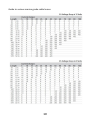
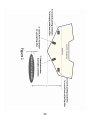
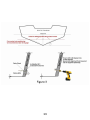
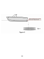
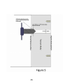
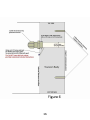
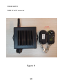
Lampsea™ High Performance Submersible Marine LED Spotlights Installation/User Manual/Warranty Model: Z40CRC XL submersible use only Version 1.1 Please read this manual carefully before proceeding 1 CONTENTS Welcome……………………………………………………………page3 Packing List………………………………………………………..page3 Structure……………………………………………………………page3-4 Specifications…………………………………………….………page4 Installation………………………………………………………..page5-7 Operation………………………………………………………….page7-8 Warranty…………………………………………………………..page8 Safety tips…………………………………………………………page9 Pics and Diagrams…………………………………………….page10-20 2 WELCOME Thank you for choosing one of Lampsea™ innovative spotlight products. Lampsea™ Z series transom patented spotlights claim to be world’s smallest, lightest, brightest, toughest, marine spotlights ever built. Our products are designed to provide you with exceptional and flawless performance for many years. Please follow our recommendations submitted herein and be the first to recommend our products to your friends. PACKING LIST 1. 2. 3. 4. 5. Z40CRC XL spotlights pair. Wireless or wired power supply (upon your choice). Cross connection splash proof marine box (one unit). Dedicated special power cable. Mounting screws SS316 (8 pieces). STRUCTURE Z series spotlights are made of high quality low carbon austenitic Stainless Steel Alloy AISI316L capable to withstand the most aggressive environmental conditions which are met in the seawater. Internally they are equipped with a high performance and patented heat exchanger which keeps the LED running cool provided the spotlights are used within the sea. Additionally a thermal protection is embedded within each spotlight to protect it from overheating in case an accidental operation is taking place off water. All spotlights carry a special and patented sealing which has been approved according to IP66/68 standard up to 100 meters deep for internal wiring. The lens is made of Borosilicate fireproof glass and its converging angle is 40 degrees. All Lampsea™ High Performance LED Spotlights are Nitrogen 3 Gas Charged for Crystal Clear operation under any environmental temperatures. They never create internal humidity which is caused by trapped air and extreme temperature impacts at freezing temperatures. Moreover all the internal construction is galvanically isolated meaning that neither the positive nor the negative power wires have contact with the spotlight’s housing. This is done for advanced corrosion resistance. Z40CRC XL SPECIFICATIONS Inclined SS316L precision machined body 32 Watts Single high power LED multi-die emitter made by Cree® 4000 lumens per spotlight Up to 125 lumens per Watt 5700 Kelvin Cool White Patented high performance heat exchanger Overheat protection Patented sealing IP66/IP68 certified up to 10 Atm or 100 meters respectively 99.96% pure Nitrogen gas charged LED chamber Multi-perspective Total Internal Reflection (TIR Collimator), with high transmittance and high directivity, made from 500⁰C fireproof Borosilicate3.3 glass, protected by ring extension Self cleaned from sea growth provided the spotlights are activated underwater accordingly. Weight to lumens ratio: as low as 0.13 grams per lumen (the least globally known). PWM precision power supply with reverse polarity protection and efficiency up to 92%. Wireless at 433MHz or wired dimming control availability Wireless diming at 433MHz 20meters radio coverage(open field) 4 INSTALLATION ΑΤΤΕΝΤΙΟΝ!!! The following instructions are NOT covering any mitigating corrosion procedures as this is out of the installation scope. Installation procedure requires professional sκill and adequate knowledge by the installer. An ABYC® certified marine engineer is strongly recommended to do your wiring. WARNING: All below procedures are indented to be carried out by qualified personnel with the boat on the trailer OUT OF THE SEA! Any attempt to drill holes on the transom while the boat is in the sea can cause severe injury, boat sinking or death. STEP 1: Before proceeding observe your personnel’s and personal safety doing an initial check for fuel leakages and fumes within the working area and the cabin. You may need a special fume detector for this. This is A MUST when performing electro-mechanical works inside a boat. DO NOT PROCEED if an alarm signal for Fuel leakage is sounding. You can ONLY proceed to the next steps if Fuel leakage test is FULLY PASSED. STEP 2: For essential security reasons carefully disconnect vessel’s battery/ies prior starting the process and remove all objects placed by the rear side of your boat’s transom. Free your space for work. STEP 3: Clean the transom Internal and External surfaces with a mild kitchen soap and rinse with clean water thoroughly. Let the surfaces well dry. STEP 4: Using a laser gage locate the exact drill spots being absolutely sure that you will not cause any damage to the boat’s safety chambers. STEP 5: After spotting the exact positions of installation, be sure the external transom’s surface is perfectly flat and then carefully mark 5 the Left and Right cable holes paying attention not to install the spotlight at a lower level from the one recommended. Check Figure 2. Failure to do so can cause damage to the boat and the spotlight. STEP 6: Using a long shank 3-5mm drill and a vertical support drive drill the cable hole which goes all the way in the transom up until it exits the other side. Check Figures 3,5 and 6. STEP 7: Using a 7mm long shank drill and a vertical drive support repeat step 6 in order to reach the exact hole diameter. STEP 8: Gently insert the spotlight’s cable and can mark the 4 blind securing holes. STEP 9: Check included A4 mounting screws diameter and height. STEP 10: Open the 1 blind hole at 15-25% smaller diameter than the original external diameter of the mounting screws. STEP11: Now insert the mounting screw and create the thread within the mounting holes. Be careful not to over rev. the screw as it can get overheated and damaged. Check the video installation included. STEP 12: Repeat the procedure for the remaining screws. Using an alcohol based cleaner now clean the transom’s surface to proceed to next step. STEP 13: Now from the inside of the boat you drill a 5mm inclined daughter hole which will meet the master cable hole at no more than 2cm length. Check Figure 6.This is done for better sealing performance and in order to use the cable glands included in your package to secure and seal the cable from inside the boat. STEP 14: Now re-bore the rear end of the hole meaning the one inside the boat using an 11.5mm drill and DO NOT go deeper than 10mm. Once done please use a ¼” pipe tap wrench to make the appropriate cable gland’s internal thread seat. STEP15: Next attach the gland and remove the cover so you can now insert the spotlight’s cable through the transom’s body. STEP 16: Tighten temporarily the gland’s cover, insert the marine silicone’s dispenser nozzle in the daughter hole and press up until the compound (we recommend marine grade Sikaflex 291i or similar) exits to the outer side. This is an additional sealing protection procedure not shown in the video. 6 STEP 17: Once done apply silicone compound in all 4 blind holes as well. Also apply silicone compound all over the rear spotlight’s base. Un-tighten the gland so as to push gently the cable and tighten the 4 external mounting spotlight screws at no more than 4.5 Nm or 40 foot pounds force. In this process excess silicone compound agent will overflow the spotlight’s bottom. Don’t worry. STEP 18: Pull inside and gently the cable and hand tighten the cable gland’s cover nut. STEP 19: Spread around the spotlight’s base the compound and then wipe it gently off in order to make a nice uniform sealing. Re-check secure installation and leave the boat off the water for at least 24hours for the sealing-bonding agent to cure. After that time you can launch the vessel in the sea. STEP 20: Finally when the vessel is launched you MUST make a final inspection for leakages to ensure everything is well done. BEFORE POWERING UP THE UNITS: Following the included electrical safety instructions diagram mount and connect the power supply using also the connection box supplied along. Avoid using long battery marine cables to run over under the hull. The longer the cables the thicker the wire core you must select. Use only marine grade cables. The system MUST be powered through a separate 12VDC fused switch at the range of 6Amps fuse. OPERATION POWERING UP THE UNITS To check correct operation power up the unit and press the ON button on the spotlight’s remote control. The spotlights must turn ON. You can check diming the spotlights by continuously soft pressing the DOWN arrow on the remote control. 7 It takes 15-20seconds to reach the lowest limit. The spotlights will seem dimmed. You can return now to full power by gently pressing respectively the UP arrow for 20 seconds approximately. Avoid using the spotlights OFF water for more than 2 minutes otherwise they will get overheated and they may start flashing once the protector is engaged. These spotlights dissipate heat into the sea and therefore they need to operate exclusively underwater. Let the spotlights to cool and silicone to cure for at least 24 hours before launching the boat. WARRANTY Your Lampsea™ product has undergone handmade assembly to comply with our high quality standards withstanding harsh environmental stresses as those met in sea water. Each Lampsea™ product is covered for 2 years warranty free from defects in workmanship to any component. This warranty does not cover failures caused by: Unauthorized attempt to open the units, bad installations, overvoltage or lightning impacts, misuse, abuse, carriage impacts during shipping, any other external cause including fires, weather disasters or failure to comply with our required prerequisites. Under these circumstances but not limited to, warranty will be void. Should you have any problem please call your dealer where you purchased the product bringing along the receipt. You can always communicate with us at: [email protected] or call us at +30-210-284-7981 We will be very happy to assist you. 8 SAFETY TIPS Spotlights MUST be installed in a safe transom’s location not overhanging or interfering to boat’s tack. Check Figures 2 and 3. Spotlights MUST NOT be galvanically attached or connected to any other boat’s metal part on the transom. DO NOT STARE at spotlights when in operation. Eye injury can result. Spotlight’s body can get hot while testing off water. AVOID touching. Use safety mask and clothes while performing installation procedure. Use safety welding goggles to check operation of the spotlights. DO NOT use impact pressure to install the spotlights. Always use a separate fused switch to control your spotlights. Check Figure 10. Use your Lampsea™ downlights for safe anchorage or shallow access. When operating for long time at night be sure your batteries have enough power and are fully charged. Always preserve boat passengers’ safety including yours. When your boat is left for a long time in a marina, sea-growth may normally cover the spotlight’s body and lens. Sea-growth will automatically be removed once you switch ON the spotlights. Under no circumstance try to open or modify the spotlights including the power supply as this will cause damage to the spotlight and will permanently void your warranty. Your spotlights need to be plugged to their own power supply. Do not try to connect the spotlights to any third party power supply as this will damage your spotlights and will consequently affect your warranty. If your spotlights get overheated then you will notice they are flashing. This will normally happen only if you “push” them to operation off water. To obtain maximum performance and long service life avoid using the spotlights off water. 9 Guide to various marine grade cable losses: 10 11 12 13 14 15 16 17 Figure 8 18 POWER SUPPLY PWM DC to DC converter Figure 9 19 POWER SUPPLY PWM DC to DC converter approved wiring Figure 10 20 NOTES ………………………………………………………………………………………………………………… ………………………………………………………………………………………………………………… ………………………………………………………………………………………………………………… ………………………………………………………………………………………………………………… ………………………………………………………………………………………………………………… ………………………………………………………………………………………………………………… ………………………………………………………………………………………………………………… ………………………………………………………………………………………………………………… ………………………………………………………………………………………………………………… ………………………………………………………………………………………………………………… ………………………………………………………………………………………………………………… ………………………………………………………………………………………………………………… ………………………………………………………………………………………………………………… ………………………………………………………………………………………………………………… ………………………………………………………………………………………………………………… ………………………………………………………………………………………………………………… ………………………………………………………………………………………………………………… ………………………………………………………………………………………………………………… ………………………………………………………………………………………………………………… ………………………………………………………………………………………………………………… ………………………………………………………………………………………………………………… ………………………………………………………………………………………………………………… ………………………………………………………………………………………………………………… ………………………………………………………………………………………………………………… ………………………………………………………………………………………………………………… ………………………………………………………………………………………………………………… …………………………………………………………………………………………………………………. 21 Complies to IP66/68 standard up to 100meters operational depth. Complies to EN-60945: 2002 standard. Complies to ASTM B117 standard. Lampsea™: 8 Agiou Georgiou P. Iraklio/Attikis/14122Athens/Greece. Tel: +30-210-284-7981 or +30-690-687-1020 www.lampsea.com email: [email protected] Lampsea™ MRN01594 is an official member of Recycling Appliances SA. for alternative management of W.E.E.E. 22