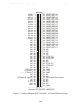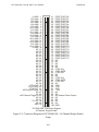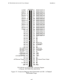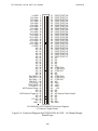
1
PCI-DAS1000,
PCI-DAS1001
&
PCI-DAS1002
Multifunction
Analog & Digital I/O
User’s Manual
Revision 2, March, 2002
© Copyright 2002, Measurement Computing Corporation
MEGA-FIFO, the CIO prefix to data acquisition board model numbers, the PCM prefix to data
acquisition board model numbers, PCM-DAS08, PCM-D24C3, PCM-DAC02, PCM-COM422,
PCM-COM485, PCM-DMM, PCM-DAS16D/12, PCM-DAS16S/12, PCM-DAS16D/16, PCMDAS16S/16, PCI-DAS6402/16, Universal Library, InstaCal, Harsh Environment Warranty and
Measurement Computing Corporation are registered trademarks of Measurement Computing
Corporation.
IBM, PC, and PC/AT are trademarks of International Business Machines Corp. Windows is a
trademark of Microsoft Corp. All other trademarks are the property of their respective owners.
Information furnished by Measurement Computing Corp. is believed to be accurate and reliable.
However, no responsibility is assumed by Measurement Computing Corporation neither for its use;
nor for any infringements of patents or other rights of third parties, which may result from its use.
No license is granted by implication or otherwise under any patent or copyrights of Measurement
Computing Corporation.
All rights reserved. No part of this publication may be reproduced, stored in a retrieval
system, or transmitted, in any form by any means, electronic, mechanical, by
photocopying, recording or otherwise without the prior written permission of
Measurement Computing Corporation.
NOTICE
Measurement Computing Corporation does not authorize any Measurement
Computing Corporation product for use in life support systems and/or
devices without the written approval of the President of Measurement
Computing Corporation Life support devices/systems are devices or
systems which, a) are intended for surgical implantation into the body, or b)
support or sustain life and whose failure to perform can be reasonably
expected to result in injury. Measurement Computing Corp. products are not
designed with the components required, and are not subject to the testing
required to ensure a level of reliability suitable for the treatment and
diagnosis of people.
HM PCI-DAS100#.doc
ii
Table of Contents
1
Introduction........................................................................................................... 1-1
2
Installation............................................................................................................. 2-1
2.1
2.2
2.3
2.4
3
Programming & Applications.............................................................................. 3-1
3.1
3.2
3.3
4
Software Installation ....................................................................................... 2-1
Hardware Installation...................................................................................... 2-1
Connector Pinout Diagrams ............................................................................ 2-2
Connecting Signals to the PCI-DAS1000 ....................................................... 2-7
Programming Languages ................................................................................ 3-1
Packaged Application Programs ..................................................................... 3-1
Register Level Programming .......................................................................... 3-1
Calibration............................................................................................................. 4-2
4.1
Calibration Configuration - Analog Inputs ..................................................... 4-2
4.2
Calibration Configuration - Analog Outputs (PCI-DAS1001 & PCI-DAS1002
Only) 4-3
5
Specifications: PCI-DAS1000 & 1001 ................................................................. 5-1
6
Specifications: PCI-DAS1002 .............................................................................. 6-1
iii
This page is blank.
PCI-DAS1000, 1001 & 1002 User's Manual
Introduction
1 Introduction
The PCI-DAS1000, PCI-DAS1001 and PCI-DAS1002 are multifunction analog and
digital I/O boards designed to operate in computers with PCI bus accessory slots. The
boards have the following capabilities:
•
16 single-ended or eight differential analog inputs with sample rates as high as
250 kHz.
•
24-bits of parallel digital I/O
•
Three, user-accessible, 16-bit counters.
•
Two analog output channels (PCI-DAS1001 and PCI-DAS1002 only)
The board’s analog input ranges are as follows:
PCI-DAS1000, PCI-DAS1002
Bipolar:
±10V, ±5V, ±2.5V, and ±1.25V
Unipolar: 0 to 10V, 0 to 5V, 0 to 2.5V and 0 to 1.25V
PCI-DAS1001
Bipolar:
±10V, ±1.0V, ±0.1V, ±0.01V
Unipolar: 0 to 10V, 0 to 1.0V, 0 to 0.1V, 0 to 0.01V
The PCI-DAS1000 series is fully plug-and-play with no switches or jumpers to set. The
boards are self-calibrating with no potentiometers to adjust. All calibration is performed
via software and on-board trim D/A converters.
The PCI-DAS1000 series is fully supported by the powerful Universal Library software as
well as a wide variety of application software packages including SoftWIRE.
NOTE:
Unless a specific model code is required, this manual references the PCI-DAS1000 as a
general term.
1-1
PCI-DAS1000, 1001 & 1002 User's Manual
Installation
2 Installation
2.1
Software Installation
The board has no switches or jumpers to set. The simplest way to configure your board is
to use the InstaCalTM program provided on the CD (or floppy disk). InstaCalTM will create
a configuration file that your application software (and the optional Universal LibraryTM)
will refer to so the software you use will automatically have access to the exact
configuration of the board.
Please refer to the Software Installation Manual regarding the installation and operation of
InstaCal.
2.2
Hardware Installation
The PCI-DAS1000 series boards are completely plug and play. There are no switches or
jumpers to set. Configuration is controlled by your systems’ BIOS. Follow the steps
shown below to install your PCI board.
WARNING
Do not unplug the computer when installing the board.
Doing so removes the computer’s ground.
1.
Turn your computer off, open it up, and insert the PCI-DAS1000 board into
any available PCI slot.
2.
Close your computer up and turn it on.
3.
If you are using an operating system with support for Plug and Play (such as
Windows 95 or 98), a dialog box will pop up as the system loads indicating
that new hardware has been detected. If the information file for this board is
not already loaded onto your PC, you will be prompted for a disk containing
it. The InstaCal software supplied with your board contains this file. Insert
the disk or CD and click OK.
2-1
PCI-DAS1000, 1001 & 1002 User's Manual
2.3
Installation
Connector Pinout Diagrams
The PCI-DAS1000 series boards use a 100-pin I/O connector. See Figures 2-1 and 2-2 for
the PCI-DAS1000.
See Figures 2-3 and 2-4 for the PCI-DAS1001 and PCI-DAS1002, 8-channel differential
and 16-channel single ended respectively.
2-2
PCI-DAS1000, 1001 & 1002 User's Manual
LLGND
CH0 HI
CH0 LO
CH1 HI
CH1 LO
CH2 HI
Ch2 LO
Ch3 HI
Ch3 LO
CH4 HI
Ch4 LO
Ch5 HI
Ch5 LO
Ch6 HI
Ch6 LO
Ch7 HI
Ch7 LO
LLGND
NC
NC
NC
NC
NC
NC
NC
NC
NC
NC
NC
NC
NC
NC
NC
NC
NC
NC
NC
NC
CTR4 CLK
CTR4 GATE
CTR4 OUT
A/D External Pacer
NC
NC
A/D External Trigger In
NC
NC
PC +5V
NC
GND
Installation
1
2
3
4
5
6
7
8
9
10
11
12
13
14
15
16
17
18
19
20
21
22
23
24
25
26
27
28
29
30
31
32
33
34
35
36
37
38
39
40
41
42
43
44
45
46
47
48
49
50
51
52
53
54
55
56
57
58
59
60
61
62
63
64
65
66
67
68
69
70
71
72
73
74
75
76
77
78
79
80
81
82
83
84
85
86
87
88
89
90
91
92
93
94
95
96
97
98
99
100
FIRST PORT A0
FIRST PORT A1
FIRST PORT A2
FIRST PORT A3
FIRST PORT A4
FIRST PORT A5
FIRST PORT A6
FIRST PORT A7
FIRST PORT B0
FIRST PORT B1
FIRST PORT B2
FIRST PORT B3
FIRST PORT B4
FIRST PORT B5
FIRST PORT B6
FIRST PORT B7
FIRST PORT C0
FIRST PORT C1
FIRST PORT C2
FIRST PORT C3
FIRST PORT C4
FIRST PORT C5
FIRST PORT C6
FIRST PORT C7
NC
NC
NC
NC
NC
CTR6 CLK
CTR6 GATE
CTR6 OUT
NC
NC
CTR5 CLK
CTR5 GATE
CTR5 OUT
NC
GND
+12V
GND
–12V
NC
NC
A/D Internal Pacer Output
NC
NC
NC
NC
GND
PCI-DAS1000 Connector Diagram
8 Channel, DIFFERENTIAL ANALOG-IN
Figure 2-1. Connector Diagram for PCI-DAS1000 - 8-Channel Differential Usage
2-3
PCI-DAS1000, 1001 & 1002 User's Manual
LLGND
Ch0 High
Ch8 High
Ch1 High
Ch9 High
Ch2 High
Ch10 High
Ch3 High
Ch11 High
Ch4 High
Ch12 High
Ch5 High
Ch13 High
Ch6 High
Ch14 High
Ch7 High
Ch15 High
LLGND
NC
NC
NC
NC
NC
NC
NC
NC
NC
NC
NC
NC
NC
NC
NC
NC
NC
NC
NC
NC
CTR4 CLK
CTR4 GATE
CTR4 OUT
A/D External Pacer
NC
NC
A/D External Trigger In
NC
NC
PC +5V
NC
GND
Installation
1
2
3
4
5
6
7
8
9
10
11
12
13
14
15
16
17
18
19
20
21
22
23
24
25
26
27
28
29
30
31
32
33
34
35
36
37
38
39
40
41
42
43
44
45
46
47
48
49
50
51
52
53
54
55
56
57
58
59
60
61
62
63
64
65
66
67
68
69
70
71
72
73
74
75
76
77
78
79
80
81
82
83
84
85
86
87
88
89
90
91
92
93
94
95
96
97
98
99
100
FIRST PORT A0
FIRST PORT A1
FIRST PORT A2
FIRST PORT A3
FIRST PORT A4
FIRST PORT A5
FIRST PORT A6
FIRST PORT A7
FIRST PORT B0
FIRST PORT B1
FIRST PORT B2
FIRST PORT B3
FIRST PORT B4
FIRST PORT B5
FIRST PORT B6
FIRST PORT B7
FIRST PORT C0
FIRST PORT C1
FIRST PORT C2
FIRST PORT C3
FIRST PORT C4
FIRST PORT C5
FIRST PORT C6
FIRST PORT C7
NC
NC
NC
NC
NC
CTR6 CLK
CTR6 GATE
CTR6 OUT
NC
NC
CTR5 CLK
CTR5 GATE
CTR5 OUT
NC
GND
+12V
GND
–12V
NC
NC
A/D Internal Pacer Output
NC
NC
NC
NC
GND
PCI-DAS1000 Connector Diagram
16 Channel, Single-Ended
Figure 2-2. Connector Diagram for PCI-DAS1000 - 16-Channel Single-Ended
Usage
2-4
PCI-DAS1000, 1001 & 1002 User's Manual
LLGND
CH0 HI
CH0 LO
CH1 HI
CH1 LO
CH2 HI
Ch2 LO
Ch3 HI
Ch3 LO
CH4 HI
Ch4 LO
Ch5 HI
Ch5 LO
Ch6 HI
Ch6 LO
Ch7 HI
Ch7 LO
LLGND
NC
NC
NC
NC
NC
NC
NC
NC
NC
NC
NC
NC
NC
NC
NC
NC
D/A GND 0
D/A OUT 0
D/A GND 1
D/A OUT 1
CTR4 CLK
CTR4 GATE
CTR4 OUT
A/D External Pacer
NC
NC
A/D External Trigger In
NC
NC
PC +5V
NC
GND
Installation
1
2
3
4
5
6
7
8
9
10
11
12
13
14
15
16
17
18
19
20
21
22
23
24
25
26
27
28
29
30
31
32
33
34
35
36
37
38
39
40
41
42
43
44
45
46
47
48
49
50
51
52
53
54
55
56
57
58
59
60
61
62
63
64
65
66
67
68
69
70
71
72
73
74
75
76
77
78
79
80
81
82
83
84
85
86
87
88
89
90
91
92
93
94
95
96
97
98
99
100
FIRST PORT A0
FIRST PORT A1
FIRST PORT A2
FIRST PORT A3
FIRST PORT A4
FIRST PORT A5
FIRST PORT A6
FIRST PORT A7
FIRST PORT B0
FIRST PORT B1
FIRST PORT B2
FIRST PORT B3
FIRST PORT B4
FIRST PORT B5
FIRST PORT B6
FIRST PORT B7
FIRST PORT C0
FIRST PORT C1
FIRST PORT C2
FIRST PORT C3
FIRST PORT C4
FIRST PORT C5
FIRST PORT C6
FIRST PORT C7
NC
NC
NC
NC
NC
CTR6 CLK
CTR6 GATE
CTR6 OUT
NC
NC
CTR5 CLK
CTR5 GATE
CTR5 OUT
NC
GND
+12V
GND
–12V
NC
NC
A/D Internal Pacer Output
NC
NC
NC
NC
GND
PCI-DAS1001 & PCI-DAS1002 Connector Diagram
8 Channel, DIFFERENTIAL ANALOG-IN
Figure 2-3. Connector Diagram for PCI-DAS1001 & 1002 - 8-Channel
Differential Usage
2-5
PCI-DAS1000, 1001 & 1002 User's Manual
LLGND
Ch0 High
Ch8 High
Ch1 High
Ch9 High
Ch2 High
Ch10 High
Ch3 High
Ch11 High
Ch4 High
Ch12 High
Ch5 High
Ch13 High
Ch6 High
Ch14 High
Ch7 High
Ch15 High
LLGND
NC
NC
NC
NC
NC
NC
NC
NC
NC
NC
NC
NC
NC
NC
NC
NC
D/A GND 0
D/A OUT 0
D/A GND 1
D/A OUT 1
CTR4 CLK
CTR4 GATE
CTR4 OUT
A/D External Pacer
NC
NC
A/D External Trigger In
NC
NC
PC +5V
NC
GND
Installation
1
2
3
4
5
6
7
8
9
10
11
12
13
14
15
16
17
18
19
20
21
22
23
24
25
26
27
28
29
30
31
32
33
34
35
36
37
38
39
40
41
42
43
44
45
46
47
48
49
50
51
52
53
54
55
56
57
58
59
60
61
62
63
64
65
66
67
68
69
70
71
72
73
74
75
76
77
78
79
80
81
82
83
84
85
86
87
88
89
90
91
92
93
94
95
96
97
98
99
100
FIRST PORT A0
FIRST PORT A1
FIRST PORT A2
FIRST PORT A3
FIRST PORT A4
FIRST PORT A5
FIRST PORT A6
FIRST PORT A7
FIRST PORT B0
FIRST PORT B1
FIRST PORT B2
FIRST PORT B3
FIRST PORT B4
FIRST PORT B5
FIRST PORT B6
FIRST PORT B7
FIRST PORT C0
FIRST PORT C1
FIRST PORT C2
FIRST PORT C3
FIRST PORT C4
FIRST PORT C5
FIRST PORT C6
FIRST PORT C7
NC
NC
NC
NC
NC
CTR6 CLK
CTR6 GATE
CTR6 OUT
NC
NC
CTR5 CLK
CTR5 GATE
CTR5 OUT
NC
GND
+12V
GND
–12V
NC
NC
A/D Internal Pacer Output
NC
NC
NC
NC
GND
PCI-DAS1001 & PCI-DAS1002 Connector Diagram
16 Channel, Single-Ended
Figure 2-4. Connector Diagram for PCI-DAS1001 & 1002 - 16-Channel SingleEndedUsage
2-6
PCI-DAS1000, 1001 & 1002 User's Manual
2.4
Installation
Connecting Signals to the PCI-DAS1000
The 100-pin connector provides a far greater signal density than the traditional 37-pin Dtype connector. For a mating cable, use the C100FF-2. This cable assembly has a 100-pin
connector that fans out to a pair of 50-pin ribbon cables. The two 50-pin ribbon cable legs
are terminated with standard 50-pin header connectors. A pair of CIO-MINI50 screw
terminal boards, a single CIO-TERM100 screw terminal board or a single SCB-50
breakout box can be used to terminate field signals and route them to the PCI-DAS1000.
The BNC16/8 series interface box provides convenient and reliable BNC connections to
each of the analog outputs.
There is additional information regarding analog signal connection and configuration at
http://www.measurementcomputing.com/signals/signals.pdf.
2-7
PCI-DAS1000, 1001 & 1002 User's Manual
Programming & Applications
3 Programming & Applications
3.1
Programming Languages
The Universal Library provides complete access to the PCI-DAS1000 functions from the
full range of Windows programming languages. If you are planning to write programs, or
would like to run the example programs for Visual Basic or any other language, please
refer to the Universal Library manual.
3.2
Packaged Application Programs
Many packaged application programs, such as SoftWIRE have drivers for the PCIDAS1000. If the software you use does not have drivers for the PCI-DAS1000, please fax
or e-mail the package name and the revision number from the install disks. We will
research the package for you and advise how to obtain the necessary drivers.
Some application drivers are included with the Universal Library package, but not with
the Application package. If you have purchased an application package directly from the
software vendor, you may need to purchase our Universal Library and drivers. Please
contact us for more information on this topic.
3.3
Register Level Programming
The PCI-DAS1000 is supported by the powerful Universal Library. We strongly
recommend that you take advantage of the Universal Library as your software interface.
The complexity of registers used for automatic calibration, combined with the PCI BIOS's
dynamic allocation of addresses and internal resources, make the PCI-DAS1000 series
challenging to program via direct register I/O operations. Direct I/O programming should
be attempted only by experienced programmers.
Although the PCI-DAS1000 is part of the larger DAS family, there is no correspondence
between register locations of the PCI-DAS1000 and boards in the CIO-DAS16 family.
Software written at the register level for the other DAS boards will not work with the PCIDAS1000. However, software based on the Universal Library should work with the PCIDAS1000 with few or no changes.
If you decide that register level programming is required for your application, information
on the register functions can be found at
http://www.measurementcomputing.com/registermaps/.
3-1
PCI-DAS1000, 1001 & 1002 User's Manual
Calibration
4 Calibration
The PCI-DAS1000 is shipped fully-calibrated from the factory with calibration
coefficients stored in nvRAM. At run time, these calibration factors are loaded into system
memory and are automatically retrieved each time a different DAC/ADC range is
specified. The user has the option to recalibrate with respect to the factory-measured
voltage standards at any time by selecting the "Calibrate" option in InstaCal. Full
calibration typically requires less than two minutes and requires no other user intervention.
4.1
Calibration Configuration - Analog Inputs
The PCI-DAS1000 provides self-calibration for the analog input and measurement
circuits, eliminating the need for external equipment and user adjustments. All
adjustments are made via 8-bit calibration DACs or 7-bit digital potentiometers referenced
to an on-board factory-calibrated standard. Calibration factors are stored on the serial
nvRAM.
A variety of methods are used to calibrate the different elements on the board. The analog
front-end has several software “knobs” to turn. Offset calibration is performed in the
instrumentation amplifier gain stage. Front-end gain adjustment is performed via a
variable attenuator/gain stage.
Figure 4-1 is a block diagram of the analog input front-end calibration system:
C al
R ef
PGA
V ariab le G ain
ADC
O ffse t A d j
7
8
T rim D ac
O ffset
D igita l O ffset P o t
(C o a rse )
T rim D ac
(Fine)
Figure4-1. Analog Front-End Calibration Block Diagram
4-2
PCI-DAS1000, 1001 & 1002 User's Manual
Calibration
4.2 Calibration Configuration - Analog Outputs (PCIDAS1001 & PCI-DAS1002 Only)
The calibration scheme for analog outputs is in Figure 4-2. The function is duplicated for
DAC0 and DAC1.
12
R ef
Trim D ac
(coarse)
Trim D ac
(fine)
DAC
A n alo g O u t
G a in A d j.
O ffset A d j.
Trim D ac
Figure 4-2. Analog Output Calibration Block Diagram - PCI-DAS1001 and PCI-DAS1002
Only
4-3
PCI-DAS1000, 1001 & 1002 User's Manual
Specifications: PCI-DAS1000 & 1001
5 Specifications: PCI-DAS1000 &
1001
Typical for 25°C unless otherwise specified
Power Consumption
+5V Operating (A/D converting to FIFO)
0.8A typical, 1.0A max
Analog input Section
A/D converter type
Resolution
Number of channels
Input Ranges
PCI-DAS1000
PCI-DAS1001
Polarity
A/D pacing
Burstmode
PCI-DAS1000
PCI-DAS1001
A/D Trigger sources
A/D Triggering Modes
Digital:
Pre-trigger:
Data transfer:
A/D conversion time:
7800
12 bits
8 differential or 16 single-ended, software
selectable
±10V, ±5V, ±2.5V, ±1.25V, 0 to 10V, 0
to 5V, 0 to 2.5V, 0 to 1.25V
fully programmable
±10V, ±1V, ±0.1V, ±0.01V, 0 to 10V, 0
to 1V, 0 to 0.1V, 0 to 0.01V
fully programmable
Unipolar/Bipolar, software selectable
Programmable: internal counter or
external source (A/D External Pacer,
positive or negative edge selectable by
software) or software polled
Software selectable option, rate = 4µs
Software selectable option, rate = 6.67µs
External digital (A/D External Trigger)
Software enabled, rising edge, hardware
trigger
Unlimited pre- and post-trigger samples.
Total # of samples must be > 512.
From 1024-sample FIFO via REPINSW,
interrupt, or software polled
3 µs
5-1
PCI-DAS1000, 1001 & 1002 User's Manual
Throughput
PCI-DAS1001
PCI-DAS1000
Relative Accuracy
Differential Linearity error:
Integral Linearity error
Gain Error (relative to calibration
reference)
0.01V Range
All other Ranges
No missing codes guaranteed
Calibration
Gain drift (A/D specs)
Zero drift (A/D specs)
Common Mode Range
CMRR @ 60Hz
Input leakage current
Input impedance
Absolute maximum input voltage
PCI-DAS1001
PCI-DAS1000
Noise Distribution (Rate = 1-250KHz,
Average % ±2 bins, Average % ±1 bin,
Average # bins)
PCI-DAS1000
All Bipolar ranges
All Unipolar ranges
PCI-DAS1001
10V Ranges
1V Ranges
0.1V Ranges
Bipolar 0.01V Range
Unipolar 0.01V Range
Specifications: PCI-DAS1000 & 1001
150 kHz
250 kHz
±1.5 LSB
±0.75 LSB
±0.5 LSB typ, ±1.5 LSB max
± 0.4% of reading Max
± 0.02% of reading Max
12 bits
Auto-calibration, calibration factors for
each range stored on board in nonvolatile RAM
±6ppm/°C
±1ppm/°C
±10V
70dB
200nA
10Meg Ohms Min
±35V
Channels 1-15: -40V to +55V power on
or off
Channel 0 : ±15V
100% / 99.5% / 4 bins
100% / 99% / 5 bins
3 bins (100%)
4 bins (100%)
10 bins (100%)
20 bins (100%)
32 bins (100%)
5-2
PCI-DAS1000, 1001 & 1002 User's Manual
Specifications: PCI-DAS1000 & 1001
Analog Output (PCI-DAS1001 only)
D/A type
Resolution
Number of channels:
Output Ranges
AD7847AR
12 bits
2
±10V, ±5V, 0 to 5V, 0 to 10V. Each
channel independently programmable.
D/A pacing
Data transfer
Offset error
Gain error
Differential nonlinearity
Integral nonlinearity
Monotonicity
D/A Gain drift
D/A Bipolar offset drift
D/A Unipolar offset drift
Software
Programmed I/O.
±600µV max, all ranges (calibrated)
±0.02% FSR max (calibrated)
±1LSB max
±1LSB max
12 bits
±2 ppm/°C max
±5 ppm/°C max
±5 ppm/°C max
Throughput
Settling time (to 0.01% of 10V step):
Slew Rate
PC-dependent
4µs typ
7V/µS
Current Drive
Output short-circuit duration
Output Coupling
Amp Output Impedance
±5 mA min
25 mA indefinite
DC
0.1 Ohms max
Miscellaneous
Power up and reset, all DAC's cleared to
0 volts, ±200mV
5-3
PCI-DAS1000, 1001 & 1002 User's Manual
Specifications: PCI-DAS1000 & 1001
Digital Input / Output
Digital Type
Configuration
Number of channels
Output High
Output Low
Input High
Input Low
Power-up / reset state
Interrupts
Interrupt enable
Interrupt sources
82C55A
2 banks of 8, 2 banks of 4,
programmable by bank as input or
output
24 I/O
3.0 volts min @ –2.5mA
0.4 volts max @ 2.5 mA
2.0 volts min, +5.5 volts absolute max
0.8 volts max, -0.5 volts absolute min
Input mode (high impedance)
INTA# - mapped to IRQn via PCI BIOS
at boot-time
Programmable
Residual counter, End-of-channel-scan,
AD-FIFO-not-empty, AD-FIFO-half-full
Counter section
Counter type
Configuration
82C54A:
82C54
Two 82C54 devices. 3 down counters per 82C54, 16
bits each
Counter 0: ADC residual sample counter.
Source: ADC Clock Gate: Internal
programmable source
Output: End-of-Acquisition interrupt
Counter 1: ADC Pacer Lower Divider
Source: 10 MHz oscillator
Gate: Tied to Counter 2 gate, programmable
source.
Output: Chained to Counter 2 Clock.
Counter 2: ADC Pacer Upper Divider
Source: Counter 1 Output.
Gate: Tied to Counter 1 gate,
programmable source.
Output: ADC Pacer clock (if
software selected),
available at user
connector (A/D
Internal Pacer Output).
5-4
PCI-DAS1000, 1001 & 1002 User's Manual
82C54B:
Clock input frequency
High pulse width (clock
input)
Low pulse width (clock
input)
Gate width high
Gate width low
Input low voltage
Input high voltage
Output low voltage
Output high voltage
Specifications: PCI-DAS1000 & 1001
Counter 0: Pretrigger Mode
Source: ADC Clock.
Gate:
External trigger
Output: End-of-Acquisition
interrupt
Counter 0 - User Counter 4 (when in non-Pretrigger
Mode)
Source: User input at 100pin connector
(CTR4 CLK) or internal 10MHz
(software selectable)
Gate:
User input at 100pin
connector (CTR4 GATE)
Output: Available at 100pin connector
(CTR4 OUT)
Counter 1: User Counter 5
Source: User input at 100pin connector
(CTR5 CLK)
Gate:
User input at 100pin connector
(CTR5 GATE)
Output: Available at 100pin connector (CTR5
OUT)
Counter 2: User Counter 6
Source: User input at 100pin connector (CTR6
CLK)
Gate:
User input at 100pin connector
(CTR6 GATE)
Output: Available at 100pin connector (CTR6
OUT)
10 Mhz max
30 ns min
50 ns min
50 ns min
50 ns min
0.8V max
2.0V min
0.4V max
3.0V min
5-5
PCI-DAS1000, 1001 & 1002 User's Manual
Specifications: PCI-DAS1000 & 1001
Environmental
Operating temperature range
Storage temperature range
Humidity
0 to 70°C
–40 to 100°C
0 to 90% non-condensing
5-6
PCI-DAS1000, 1001 & 1002 User's Manual
Specifications: PCI-DAS1002
6 Specifications: PCI-DAS1002
Typical for 25°C unless otherwise specified.
Power consumption
+5V
0.8A typical, 1.0A max
Analog input section
A/D converter type
Resolution
Number of channels
Input ranges
A/D pacing
(software programmable)
A/D trigger sources
A/D triggering modes
A/D pre-trigger mode
Burst mode
Data transfer
A/D conversion time
Analog front end settling time
Calibrated throughput
Calibration
ADS7800 or equivalent
12 bits
16 single-ended / 8 differential, software
selectable
±10V, ±5V, ±2.5V, ±1.25V, 0 to 10V, 0 to 5V, 0
to 2.5V, 0 to 1.25V software programmable
Internal counter - 82C54.
External source (A/D External Pacer) software
programmable for rising or falling edge
Software polled
External edge trigger (A/D External Trigger)
Rising or falling edge trigger - software
selectable
Unlimited pre- and post-trigger samples. Total
number of samples must be greater than 512.
Software selectable option, burst rate = 150kHz
From 1024 sample FIFO via REPINSW
Programmed I/O
3µs max
6µs for a full scale step to 1 LSB
200KHz
Auto-calibration, calibration factors for each
range stored on board in nonvolatile RAM
6-1
PCI-DAS1000, 1001 & 1002 User's Manual
Specifications: PCI-DAS1002
Accuracy
Accuracies are listed for a 200KHz sampling rate, 100 sample average, single channel
operation, a 15 minute warm-up, and operational temperatures within ±2degC of internal
calibration temperature. The calibrator test source high side is tied to Channel 0 In and the
low side tied to AGND.
Table 1 – Absolute Accuracy
Range
±10.00V
±5.000V
±2.500V
±1.250V
0 to 10.00V
0 to 5.000V
0 to 2.500V
0 to 1.250V
Absolute Accuracy
±2.5 LSB max
±2.5 LSB max
±2.5 LSB max
±2.5 LSB max
±2.5 LSB max
±2.5 LSB max
±2.5 LSB max
±2.5 LSB max
Each PCI-DAS1002 is tested at the factory to assure the board’s overall error does not
exceed accuracy limits described in Table 1 above.
Table 2 – Calibrated Accuracy Components (in LSB)
Range
Gain Error
Offset Error
DLE
All ranges
±1.0 max
±1.0 max
±0.75 max
ILE
±0.5 max
As shown in Table 2, total board error is a combination of Gain, Offset, Differential
Linearity and Integral Linearity error. The theoretical worst-case error of the board may be
calculated by summing these component errors. Worst case errors are realized only in the
unlikely event that each of the component errors are at their maximum level, and causing
error in the same direction.
Crosstalk
Crosstalk is defined here as the influence of one channel upon another when scanning two
channels at the maximum rate. A full scale 100Hz triangle wave is input on Channel 1;
Channel 0 is tied to Analog Ground at the 100 pin user connector. The table below
summarizes the influence of Channel 1 on Channel 0 with the effects of noise removed.
The residue on Channel zero is described in LSB’s.
Condition
All Ranges
Crosstalk
2 LSB pk-pk
Per channel Rate
100 KHz
6-2
ADC Rate
200 KHz
PCI-DAS1000, 1001 & 1002 User's Manual
A/D Full-Scale Gain drift
A/D Zero drift
Common Mode Range
CMRR @ 60Hz
Input leakage current
Input impedance
Absolute maximum input
voltage
Warm-up time
Specifications: PCI-DAS1002
±0.25 LSB/°C max
±0.25 LSB/°C max
±10V min
-70dB min
±20nA max
10 MOhms min
±35 volts
15 minutes
Noise Performance
Table 3 below summarizes the noise performance for the PCI-DAS1002. Noise
distribution is determined by gathering 50K samples at 200kHz with inputs tied to ground
at the user connector.
Table 3 – Board Noise Performance
Range
0 to 1.250V
All other ranges
% within ±2 LSB
100%
100%
% within ±1 LSB
99%
100%
LSBs
4
3
LSBrms*
0.61
0.45
* RMS noise is defined as the peak-to-peak bin spread divided by 6.6
Analog output section
D/A converter type
Resolution
Number of channels
Configuration
Output Range
D/A pacing
Data transfer
AD7847AR or equivalent
12 bits
2
Voltage Output, Single-ended
±10V, ±5V, 0 to 10V, or 0 to 5V. Software
selectable. Each channel independently
programmable.
Software
Programmed I/O
6-3
PCI-DAS1000, 1001 & 1002 User's Manual
Specifications: PCI-DAS1002
Absolute Accuracy
All Ranges
±3 LSB
Calibrated Accuracy Components
Gain Error
Offset Error
Integral Linearity Error
Differential Linearity Error
±1.0 LSB max
±0.5LSB max
±1.0 LSB max
±1.0 LSB max
Each PCI-DAS1002 is tested at the factory to assure absolute accuracy.
Total board error is a combination of Gain, Offset, Integral Linearity and Differential
Linearity error. The theoretical worst-case error of the board may be calculated by
summing these component errors. Worst case error is realized only in the unlikely event
that each of the component errors are at their maximum level, and causing error in the
same direction. Although an examination of the chart and a summation of the maximum
theoretical errors shows that the board could theoretically exhibit a ±3.5 LSB error, our
testing assures this error is never realized in a board that we ship.
Monotonicity
Overall Analog Output drift
Settling time
Slew Rate
Current Drive
Output short-circuit duration
Output coupling
Output impedance
Miscellaneous
Guaranteed monotonic over temperature
±0.03 LSB/°C max
4µs to 0.01% of 10V step
7V/µs min
±5 mA min
Indefinite @25mA
DC
0.1 ohms max
Double buffered output latches
Output voltage on power up and reset: ±200mV
6-4
PCI-DAS1000, 1001 & 1002 User's Manual
Specifications: PCI-DAS1002
Counter section
Counter type
Configuration
Counter 1 – ADC residual
sample counter
Counter 2 - ADC Pacer Lower
Divider
Counter 3 - ADC Pacer Upper
Divider
Counter 4 – Pre-trigger mode
Counter 4 – Non-Pre-Trigger
mode
Counter 5 - User counter
Counter 6 - User counter
Clock input frequency
High pulse width (clock input)
Low pulse width (clock input)
Gate width high
Gate width low
Input low voltage
Input high voltage
Output low voltage
82C54
Two 82C54 devices, 3 down counters per 82C54,
16 bits each
Source: ADC clock
Gate:
Internal programmable source
Output: End of acquisition interrupt
Source: 10 MHz internal source
Gate:
Internal, programmable on/off
Output: Chained to Counter 3 Clock
Source: Counter 2 Output
Gate:
Internal, programmable on/off
Output: Programmable as ADC Pacer clock.
Available at user connector (ADC
Pacer out)
Source: ADC clock for pre-trigger mode
Gate:
External trigger for pre-trigger mode
Output: End of acquisition interrupt for pretrigger mode
Source: External at connector (CTR4 CLK)
Gate:
External at connector (CTR4 GATE)
Output: Available at connector (CTR4 OUT)
Source: External at connector (CTR5 CLK)
Gate:
External at connector (CTR5 GATE)
Output: Available at connector (CTR5 OUT)
Source: External at connector (CTR6 CLK)
Gate:
External at connector (CTR6 GATE)
Output: Available at connector (CTR6 OUT)
10Mhz max
30ns min
50ns min
50ns min
50ns min
0.8V max
2.0V min
0.4V max
6-5
PCI-DAS1000, 1001 & 1002 User's Manual
Output high voltage
Crystal Oscillator Frequency
Frequency accuracy
Specifications: PCI-DAS1002
3.0V min
10MHz
50ppm
Digital input/output section
Digital Type
Number of I/O
Configuration
Input high voltage
Input low voltage
Output high voltage (IOH = -2.5mA)
Output low voltage (IOL = 2.5mA)
Power-up / reset state
82C55
24 (Port A0 through Port C7)
• 2 banks of 8 and 2 banks of 4 or
• 3 banks of 8 or
• 2 banks of 8 with handshake
2.0V min, 5.5V absolute max
0.8V max, –0.5V absolute min
3.0V min
0.4V max
Input mode (high impedance)
6-6
PCI-DAS1000, 1001 & 1002 User's Manual
Specifications: PCI-DAS1002
Interrupt section
Interrupts
Interrupt enable
Interrupt sources
PCI INTA# - mapped to IRQn via PCI BIOS
at boot-time
Programmable. Default = disabled.
• Residual sample counter
• A/D End-of-channel-scan
• A/D FIFO-not-empty
• A/D FIFO-half-full
• A/D Pacer
Miscellaneous
+5 Volts
+12 Volts
-12 Volts
Available at I\O connector (PC+5V)
Available at I\O connector (PC +12V)
Available at I\O connector (PC –12V)
Environmental
Operating Temperature Range
Storage Temperature Range
Humidity
0 to 70°C
-40 to 100°C
0 to 95% non-condensing
Mechanical
Card dimensions
PCI half card: 174.63mm(L) x 106.86mm(H)
x 14.48mm(D)
6-7
PCI-DAS1000, 1001 & 1002 User's Manual
Specifications: PCI-DAS1002
Connector and Pin Out
8 Channel Differential Mode
Pin
1
2
3
4
5
6
7
8
9
10
11
12
13
14
15
16
17
18
19
20
21
22
23
24
25
26
27
28
29
30
31
32
33
34
35
36
37
38
39
40
41
42
43
44
45
46
47
48
49
50
Signal Name
LLGND
CH0 HI
CH0 LO
CH1 HI
CH1 LO
CH2 HI
CH2 LO
CH3 HI
CH3 LO
CH4 HI
CH4 LO
CH5 HI
CH5 LO
CH6 HI
CH6 LO
CH7 HI
CH7 LO
LLGND
N/C
N/C
N/C
N/C
N/C
N/C
N/C
N/C
N/C
N/C
N/C
N/C
N/C
N/C
N/C
N/C
D/A GND 0
D/A OUT 0
D/A GND 1
D/A OUT 1
CTR4 CLK
CTR4 GATE
CTR4 OUT
A/D EXTERNAL PACER
N/C
N/C
A/D EXTERNAL TRIGGER IN
N/C
N/C
PC +5V
N/C
GND
Pin
51
52
53
54
55
56
57
58
59
60
61
62
63
64
65
66
67
68
69
70
71
72
73
74
75
76
77
78
79
80
81
82
83
84
85
86
87
88
89
90
91
92
93
94
95
96
97
98
99
100
6-8
Signal Name
FIRST PORT A 0
FIRST PORT A 1
FIRST PORT A 2
FIRST PORT A 3
FIRST PORT A 4
FIRST PORT A 5
FIRST PORT A 6
FIRST PORT A 7
FIRST PORT B 0
FIRST PORT B 1
FIRST PORT B 2
FIRST PORT B 3
FIRST PORT B 4
FIRST PORT B 5
FIRST PORT B 6
FIRST PORT B 7
FIRST PORT C 0
FIRST PORT C 1
FIRST PORT C 2
FIRST PORT C 3
FIRST PORT C 4
FIRST PORT C 5
FIRST PORT C 6
FIRST PORT C 7
N/C
N/C
N/C
N/C
N/C
CTR6 CLK
CTR6 GATE
CTR6 OUT
N/C
N/C
CTR5 CLK
CTR5 GATE
CTR5 OUT
N/C
GND
+12V
GND
-12V
N/C
N/C
A/D INTERNAL PACER OUTPUT
N/C
N/C
N/C
N/C
GND
PCI-DAS1000, 1001 & 1002 User's Manual
Specifications: PCI-DAS1002
16 Channel Single-Ended Mode
Pin
1
2
3
4
5
6
7
8
9
10
11
12
13
14
15
16
17
18
19
20
21
22
23
24
25
26
27
28
29
30
31
32
33
34
35
36
37
38
39
40
41
42
43
44
45
46
47
48
49
50
Signal Name
LLGND
CH0 HI
CH8 HI
CH1 HI
CH9 HI
CH2 HI
CH10 HI
CH3 HI
CH11 HI
CH4 HI
CH12 HI
CH5 HI
CH13 HI
CH6 HI
CH14 HI
CH7 HI
CH15 HI
LLGND
N/C
N/C
N/C
N/C
N/C
N/C
N/C
N/C
N/C
N/C
N/C
N/C
N/C
N/C
N/C
N/C
D/A GND 0
D/A OUT 0
D/A GND 1
D/A OUT 1
CTR4 CLK
CTR4 GATE
CTR4 OUT
A/D EXTERNAL PACER
N/C
N/C
A/D EXTERNAL TRIGGER IN
N/C
N/C
PC +5V
N/C
GND
Pin
51
52
53
54
55
56
57
58
59
60
61
62
63
64
65
66
67
68
69
70
71
72
73
74
75
76
77
78
79
80
81
82
83
84
85
86
87
88
89
90
91
92
93
94
95
96
97
98
99
100
6-9
Signal Name
FIRST PORT A 0
FIRST PORT A 1
FIRST PORT A 2
FIRST PORT A 3
FIRST PORT A 4
FIRST PORT A 5
FIRST PORT A 6
FIRST PORT A 7
FIRST PORT B 0
FIRST PORT B 1
FIRST PORT B 2
FIRST PORT B 3
FIRST PORT B 4
FIRST PORT B 5
FIRST PORT B 6
FIRST PORT B 7
FIRST PORT C 0
FIRST PORT C 1
FIRST PORT C 2
FIRST PORT C 3
FIRST PORT C 4
FIRST PORT C 5
FIRST PORT C 6
FIRST PORT C 7
N/C
N/C
N/C
N/C
N/C
CTR6 CLK
CTR6 GATE
CTR6 OUT
N/C
N/C
CTR5 CLK
CTR5 GATE
CTR5 OUT
N/C
GND
+12V
GND
-12V
N/C
N/C
A/D INTERNAL PACER OUTPUT
N/C
N/C
N/C
N/C
GND
EC Declaration of Conformity
We, Measurement Computing Corporation, declare under sole responsibility that
the products:
Part Number
Description
PCI-DAS1000
High speed analog input board for
the PCI bus
PCI-DAS1001
High speed analog input board for
the PCI bus
PCI-DAS1002
High speed analog input board for
the PCI bus
to which this declaration relates, meets the essential requirements, is in
conformity with, and CE marking has been applied according to the relevant EC
Directives listed below using the relevant section of the following EC standards
and other normative documents:
EU EMC Directive 89/336/EEC:
electromagnetic compatibility.
Essential
requirements
relating
to
EU 55022 Class B: Limits and methods of measurements of radio interference
characteristics of information technology equipment.
EN 50082-1: EC generic immunity requirements.
IEC 801-2: Electrostatic discharge requirements for industrial process
measurement and control equipment.
IEC 801-3: Radiated electromagnetic field requirements for industrial process
measurements and control equipment.
IEC 801-4: Electrically fast transients for industrial process measurement and
control equipment.
Carl Haapaoja, Director of Quality Assurance
Measurement Computing Corporation
16 Commerce Boulevard,
Middleboro, Massachusetts 02346
(508) 946-5100
Fax: (508) 946-9500
E-mail: [email protected]
www. measurementcomputing.com