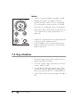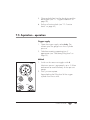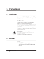
1
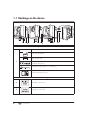
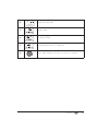
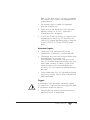
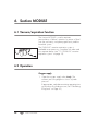
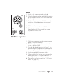
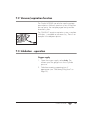
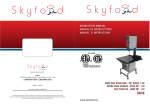
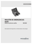
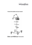
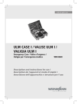
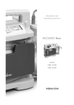
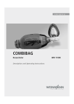
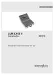
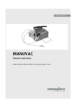
Module System
Oxygen MODULE
WM 22200
Suction MODULE
WM 22220
Combi MODULE
WM 22210
Interface MODULE
WM 22230
CPAP MODULE
WM 29100
Description and instructions for use
Contents
1. Overview . . . . . . . . . . . . . . . . . . . . 3
1.1 Markings on the device . . . . . . . 4
2. Description of device . . . . . . . . . . . . 6
2.1 Intended use . . . . . . . . . . . . . . . 6
2.2 User qualification . . . . . . . . . . . . 6
2.3 Combination options . . . . . . . . . 7
2.4 Storage . . . . . . . . . . . . . . . . . . 7
3. Safety instructions . . . . . . . . . . . . . . 8
3.1 Safety instructions . . . . . . . . . . . . 8
3.2 Contraindications . . . . . . . . . . . 11
3.3 Side effects . . . . . . . . . . . . . . . 12
4. Assembly . . . . . . . . . . . . . . . . . . . 13
4.1 Assembling the modules . . . . . . 13
4.2 Connecting oxygen supply. . . . . 14
4.3 External oxygen connection . . . . 16
4.4 Assembling breathing station . . . 17
4.5 Assembling the bubble humidifier 17
4.6 Assembling the OMNIVAC
secretion aspiration system . . . . . 18
4.7 Assembling the CPAP valve . . . . 20
5. Oxygen MODULE . . . . . . . . . . . . . 21
5.1 Inhalation function . . . . . . . . . . 21
5.2 Operation . . . . . . . . . . . . . . . 22
5.3 Stop inhalation . . . . . . . . . . . . 23
6. Suction MODULE . . . . . . . . . . . . . . 24
6.1 Vacuum/aspiration function . . . . 24
6.2 Operation . . . . . . . . . . . . . . . 24
6.3 Stop aspiration . . . . . . . . . . . . 25
7. Combi MODULE . . . . . . . . . . . . . . 26
7.1 Inhalation function . . . . . . . . . . 26
7.2 Vacuum/aspiration function . . . . 27
7.3 Inhalation - operation . . . . . . . . 27
7.4 Stop inhalation . . . . . . . . . . . . 28
7.5 Aspiration - operation . . . . . . . . 29
7.6 Stop aspiration . . . . . . . . . . . . 30
8. Interface MODULE . . . . . . . . . . . . . 31
8.1 Coupling/oxygen connection
function . . . . . . . . . . . . . . . . . 31
8.2 Operation . . . . . . . . . . . . . . . 31
9. CPAP MODULE . . . . . . . . . . . . . . .32
2
EN
Contents
9.1 CPAP function . . . . . . . . . . . . . 32
9.2 Operation . . . . . . . . . . . . . . . . 32
10. OMNIVAC secretion aspiration
system . . . . . . . . . . . . . . . . . . . . .35
10.1 Starting work. . . . . . . . . . . . . . 36
10.2 Aspiration. . . . . . . . . . . . . . . . 36
10.3 Stop aspiration . . . . . . . . . . . . 38
11. Hygiene treatment . . . . . . . . . . . . .39
11.1 Preparing the OMNIVAC
secretion aspiration system. . . . . 39
11.2 Cleaning, disinfecting and
sterilizing . . . . . . . . . . . . . . . . 40
11.3 Assembling the OMNIVAC
secretion aspiration system. . . . . 41
12. Function check . . . . . . . . . . . . . . . .42
12.1 Intervals . . . . . . . . . . . . . . . . . 42
12.2 Check filling . . . . . . . . . . . . . . 43
12.3 Test leaktightness . . . . . . . . . . . 44
12.4 Checking inhalation . . . . . . . . . 45
12.5 Checking aspiration . . . . . . . . . 46
12.6 Checking oxygen flow . . . . . . . 47
12.7 Testing the pressure gauge. . . . . 47
13. Troubleshooting . . . . . . . . . . . . . .48
13.1 Adjusting pressure gauge . . . . . 49
14. Servicing . . . . . . . . . . . . . . . . . . . .50
14.1 Intervals . . . . . . . . . . . . . . . . . 50
14.2 Scope of servicing . . . . . . . . . . 50
14.3 Disposal. . . . . . . . . . . . . . . . . 51
15. Scope of supply . . . . . . . . . . . . . . .52
15.1 Standard scope of supply . . . . . 52
15.2 Accessories. . . . . . . . . . . . . . . 54
15.3 Replacement parts . . . . . . . . . . 56
16. Technical data . . . . . . . . . . . . . . . .57
16.1 Determining oxygen
concentration . . . . . . . . . . . . . 58
16.2 External oxygen output . . . . . . . 61
16.3 Oxygen output, inhalation . . . . . 62
16.4 Aspiration performance . . . . . . . 62
17. Warranty . . . . . . . . . . . . . . . . . . .64
18. Declaration of conformity . . . . . . .65
1. Overview
1
2
1
3
2
3
MODUL
Oxygen
O2
Inhalation
MODUL
Suction
I
I
Medium
Vac
0
0
2,7 - 6 bar
O2
8
7
l/min
2,7 - 6 bar
O2
8
5 4
2
6
Suction MODULE
Oxygen MODULE
1
5 4
l/min
3
1
2
3
MODUL
Combi
Medium
Vac
I
O2
0
0
2,7 - 6 bar
O2
9
I
l/min
7
6 5 4
8
Combi MODULE
1
2
8
Interface MODULE
Key
3
MODUL
CPAP
I
2,7 - 6 bar
O2
O2
8 10
11 5
CPAP MODULE
4
0
hPa
1 Oxygen inlet with nonreturn valve (not seen)
2 Display
3 Oxygen outlet
4 Toggle switch
5 Regulator dial
6 Vacuum connection
7 Inhalation connection
8 External oxygen connection
9 Vacuum on/off switch
10 Pressure measurement tube connection
11 CPAP valve connection
Overview
EN
3
1.1 Markings on the device
O2
2
3 8
1
4
5 8
6
78
ID plate for MODULES
SN
Serial number of device
Date of manufacture
Type of gas: O2
CE symbol (confirms that the product conforms to the applicable
European directives)
1
:
Permitted inlet pressure 2.7 - 6 bar O2
Follow instructions for use
Other markings
4
2
Inhalation connection
3
Aspiration connection
EN
Overview
4
O2
Oxygen inlet and outlet
2,7-6 bar
5
6
Oxygen outlet
O2
CPAP
O2 outlet for CPAP
7
Permitted inlet pressure 2.7 - 6 bar O2
8
Service label: indicates when the next service is required.
Overview
EN
5
2. Description of device
2.1 Intended use
Oxygen Suction Combi Interface CPAP
MODULE MODULE MODULE MODULE MODULE
Intended use
To increase the percentage proportion by volume of
oxygen in inhaled air
X
–
X
–
X
To create a vacuum to enable relatively large
accumulations of blood, mucus, saliva etc. as well as
viscous and solid pieces of food to be extracted from
the oral cavity, the pharyngonasal cavity and the
bronchial system with the aid of a secretion aspiration
system
–
X
X
–
–
To pass the oxygen supply on to other devices via the
coupling connection
X
X
X
X
X
To facilitate an external oxygen supply via the
coupling connection
X
X
X
X
X
To supply the CPAP valve (Boussignac CPAP valve for
CPAP MODULE) via a regulatable oxygen flow rate to
achieve and display a desired therapy pressure
–
–
–
–
X
2.2 User qualification
The modules may only be used and operated by
people with the following qualifications:
6
EN
•
medical training and instruction in non-invasive
ventilation technology.
•
instruction in how the modules work.
Description of device
2.3 Combination options
You can use modules individually or connected in
series of up to three modules.
Another option is to connect up to three modules to the
MEDUMAT ventilation device.
Always operate only one module or one
Medumat at a time. If you use modules
simultaneously, it is possible the supply of
O2 will be inadequate.
2.4 Storage
If a module is not used for an extended period, we
recommend the following procedure.
1. Perform a hygiene treatment (see “11. Hygiene
treatment” on page 39).
2. Store the module in dry conditions.
Description of device
EN
7
3. Safety instructions
3.1 Safety instructions
For your own safety and that of your patients, and in
accordance with the requirements of directive 93/
42/EEC, observe the points below.
General
8
EN
Safety instructions
•
Please read these instructions for use through
carefully. They are a constituent part of the device
and must be available at all times.
•
Read carefully through the instructions for use for
the accessories used. They form part of the
accessories.
•
Before you work with the modules, you must have
understood how to operate them.
•
Follow the section entitled “11. Hygiene
treatment” on page 39 to prevent an infection or
bacterial contamination.
•
Do not use the modules in a toxic or dusty
atmosphere.
•
Use the modules only in the permitted ambient
conditions (see “16. Technical data” on
page 57).
•
Use only the accessories mentioned in Section 15.
•
Use the modules only for the intended purpose
described (see “2.1 Intended use” on page 6).
•
You may never operate more than one device
simultaneously, otherwise it is impossible to
guarantee compliance with the specified technical
data. For the same reason, you may not operate
the modules whilst oxygen is being tapped off for
external devices.
•
The modules are not suitable for hyperbaric
(pressure chamber) use.
•
Please monitor that the devices are functioning
perfectly during use, as well – especially if
cylinder pressure is dropping.
•
In the event of a device failing, you need to have
an alternative to hand, e.g. for aspiration, the
MANUVAC manual aspiration pump in case the
Suction MODULE or Combi MODULE breaks
down.
Accessories/repairs
•
Have repair work performed only by the
manufacturer, Weinmann, or authorized staff.
•
If third-party items are used, functional failures and
restricted fitness for use may result.
Biocompatibility requirements may also not be
met. You should be aware that in these cases, any
claim under warranty or liability will be void if
neither the accessories recommended in the
instructions for use nor genuine replacement parts
are used.
•
Protect rubber parts from UV light and prolonged
exposure to sunlight, otherwise they may become
brittle and friable.
Oxygen
In combination with flammable substances (grease,
oil, alcohol etc.), highly-compressed oxygen can lead
to spontaneous explosive reactions.
•
Keep the devices and all screwed connections
absolutely free of oil and grease.
Safety instructions
EN
9
Important
•
It is essential to wash your hands before working
on the oxygen supply.
•
Smoking and naked flames are strictly prohibited
in the vicinity of fittings which carry oxygen.
•
During assembly and when changing cylinders,
tighten all screwed connections on the oxygen
supply and on the pressure reducer only by hand.
Under no circumstances may you use tools.
Excessive tightening damages the threads and
seals and then leads to leaks.
•
Secure oxygen cylinders so they cannot tip over. If
the cylinder falls on the pressure reducer or the
valve, these could be torn off, triggering a violent
explosion.
•
Ensure that the respiratory gas is adequately
temperature-controlled. Excessively warm or cold
gas may harm the patient. Please also observe the
permitted ambient conditions (see “16. Technical
data” on page 57).
•
Always open the cylinder valve slowly to prevent
hammering on the fittings.
•
Do not empty cylinders completely, otherwise
damp ambient air may penetrate and lead to
corrosion.
Inhalation
•
If you use Weinmann inhalation masks, a
dangerous rise in pressure is not possible.
•
However, please ensure that the exhaled
respiratory gas can flow away freely.
Aspiration
•
10
EN
Safety instructions
Use the Suction MODULE and the Combi
MODULE only if you are medically trained and
familiar with aspiration technology. Severe
physical injuries can be caused by incorrect use.
Important!
•
Pay particular attention during aspiration to ensure
that no injuries are caused to the patient’s oropharyngeal cavities, e.g. to the mucous membranes.
•
For bronchial aspiration, work under sterile
conditions and use only sterile aspiration catheters.
•
Dispose of fluids such as blood and secretions, as
well as parts contaminated with these fluids, as
per the guidelines in the Federal Health Gazette
entitled “Anforderungen der Hygiene an die
Abfallentsorgung” [Hygiene requirements when
disposing of waste] (published by the Federal
Office of Health and obtainable from Carl
Heymanns Verlag, Cologne).
•
Please ensure that the aspirate bottles are always
upright during aspiration, otherwise the ball of the
overflow cutout cannot reliably block the outlet.
CPAP therapy
•
The CPAP MODULE is not licensed for inhalation.
•
Use the CPAP MODULE only if you are medically
trained and familiar with CPAP therapy. Severe
physical injuries can be caused by incorrect use.
3.2 Contraindications
Observe the contraindications for the therapies in
question. These may include (examples):
•
impaired consciousness
•
lung diseases requiring intubation
•
use of mask impossible
•
undrained pneumothorax
•
intracranial hypertension.
Safety instructions
EN
11
3.3 Side effects
If the contraindications are taken into account, no side
effects are likely in use with normal oxygen.
However, observe the side effects mentioned in the
patient information leaflet entitled “Medical oxygen” in
the case of
12
EN
Safety instructions
•
newborns
•
administration of 100 % oxygen
•
administration of oxygen under elevated pressure.
4. Assembly
If the modules are supplied complete on a LIFE-BASE
or LIFE-BASE Mini carrying platform, they are
operational and you need not perform any further
assembly.
4.1 Assembling the modules
Connecting
1. Release the connection to the oxygen supply (see
“Removing an empty cylinder” on Page 15).
2. Unscrew the cover of the oxygen outlet from the
module.
If you screw the cover back on later, tighten it just
hand-tight to prevent damage to the housing.
3. Push the protective ring supplied over oxygen
outlet 3. The protective ring prevents dirt
penetrating the housing.
O–ring
Protective
ring
4. Plug the modules together.
The seal is made by the O-ring.
Assembly
EN
13
5. Connect any other modules in exactly the same
way.
No more than 3 modules may be connected,
otherwise it is impossible to guarantee compliance
with the specified technical data.
6. Screw the modules and, if appropriate, the
MEDUMAT onto the assembly plate from the back
as shown in the assembly instructions provided,
or
screw the modules to a solid wall from the back.
Please note that screws should protrude no more
than 5.5 mm into the modules.
4.2 Connecting oxygen supply
Wash your hands thoroughly before any work on the
oxygen supply. Hydrocarbon compounds (e.g. oil,
greases, alcohols for cleaning, hand cream or sticking
plaster) can lead to explosive reactions if they come
into contact with highly-compressed oxygen.
Under no circumstances use spanners or other tools
to tighten up the union nuts.
14
EN
Assembly
You should always connect the oxygen supply at the
extreme left-hand module, as oxygen inlet 1 of all
modules is equipped with a nonreturn valve.
Inlet with
nonreturn valve
The nonreturn valve ensures that the oxygen can get in
but cannot get out at this connection.
Oxygen outlet 3 has no non-return valve.
Outlet without
nonreturn valve
For the same reason, the MODULE which allows
connection to an additional external oxygen supply (in
this case an Interface MODULE) should always be
attached the furthest to the left.
Removing an empty cylinder
1. Close the valve on the oxygen cylinder.
2. Switch on a module. This allows any residual
oxygen to escape and the device is
depressurized. The screwed connection may not
be undone until the pressure gauge on the
pressure reducer is displaying “0”.
3. Switch the module off again.
4. Undo the manual screwed connection to the
cylinder.
Connecting a new cylinder
1. Briefly open the valve on the new oxygen cylinder
and close it again. This is intended to blow away
any particles of dust.
Point the valve opening away from your body as
you do this so that you injure neither yourself nor
any other person with any particles which may fly
out!
Assembly
EN
15
2. Screw the pressure reducer with the corrugated
union nut to the cylinder valve. Tighten the union
nut hand-tight.
3. Screw the pressure tube with the G 3/8 union nut
to the pressure reducer outlet.
4. Screw the other end of the pressure tube to oxygen
inlet 1 of the module.
4.3 External oxygen connection
In addition to oxygen inlet 1, you can use external
oxygen connection 8 to tap off or feed in oxygen.
Tapping off oxygen
You may not operate a module at the same time as
tapping off oxygen, otherwise the specified technical
data will not be maintained.
Feeding in oxygen
You can use the external oxygen feed for example to
allow continued working with the modules when the
oxygen cylinder is being changed.
Due to the nonreturn valves in oxygen inlet 1, oxygen
should always be fed in at the module fitted on the
extreme left.
16
EN
Assembly
4.4 Assembling breathing station
Disposable inhalation mask and nasal cannula
The disposable nasal cannula and inhalation masks
with or without economy bag are made of transparent
plastic. For hygiene reasons, they may only be used
for one patient.
1. If necessary, screw union nut 7 supplied onto the
corresponding threaded connection of the
Oxygen MODULE or the Combi MODULE.
2. When the module is used, plug the tube onto the
union nut.
4.5 Assembling the bubble humidifier
1. Unscrew the tank from the top part of the bubble
humidifier.
Assembly
EN
17
2. Screw the top part of the bubble humidifier onto
the corresponding threaded connection of the
Oxygen MODULE or the Combi MODULE by
hand.
3. Fill the bottom part up to the mark with distilled
water (aqua dest.) and screw the tank back on.
4. Push the tube for the breathing station onto the
outlet stub of the bubble humidifier.
4.6 Assembling the OMNIVAC secretion aspiration
system
The OMNIVAC secretion aspiration system is required
for aspiration using the Suction MODULE or the Combi
MODULE.
1. Screw the holder for the secretion aspirate bottles
to a suitable point.
18
EN
Assembly
2. Put both aspirate bottles in the holder.
3. Connect the bottles and the module with the
appropriate tubes. Ensure that the bottle with the
overflow cutout is connected to the module first.
We recommend fitting a hydrophobic bacteria filter
WM 22291 for the exhaust air to prevent secretion
and bacteria penetrating the module. Filter
WM 22291 is obtainable as an accessory,
individually or in sets. It is a disposable item and must
be replaced after every aspiration operation.
4. Take the vacuum tube off the module.
5. Cut a piece about 6 cm long off the vacuum tube.
6. Put this short piece of tube onto the side of the filter
marked with “TO PUMP”.
7. Plug the other end of the short piece of tube onto
the vacuum connection of the module.
8. Put the free end of the vacuum tube on the filter.
Assembly
EN
19
4.7 Assembling the CPAP valve
1. Connect the CPAP valve to the CPAP module
using the connecting tubes.
Ensure that the tubes are guided cleanly so that
they do not impede one another.
2. Perform a function check (see “12.6 Checking
oxygen flow” on page 47).
O2
Pressure
measurement
tube
20
EN
Oxygen
outlet
Assembly
5. Oxygen MODULE
5.1 Inhalation function
You can perform oxygen inhalation using the Oxygen
MODULE.
Conditions of use
Oxygen inhalation only makes sense in emergency
patients who are still breathing spontaneously. This is
the case with breathing disorders, for example.
In the event of respiratory failure, inhalation of oxygen
is by no means adequate and artificial ventilation will
be required here. The pressure of the oxygen during
inhalation is not adequate to overcome the resistance
of the respiratory tract, so not enough oxygen reaches
the lungs.
The patient is supplied with oxygen via an inhalation
mask or nasal cannula.
You can also connect the inhalation tube to a
ventilation bag to allow ventilation at an increased
oxygen concentration.
To prevent mucous membranes drying out in the case
of prolonged oxygen inhalation, you can fit a bubble
humidifier (see “4.5 Assembling the bubble humidifier”
on page 17).
Oxygen MODULE
EN
21
5.2 Operation
Oxygen supply
1. Open the oxygen supply valve slowly. The
contents pressure gauge now shows cylinder
pressure.
2. Calculate remaining operating time, if
appropriate (see “Calculating filling level” on
Page 43).
Method
MODUL
Oxygen
1. Switch on oxygen inhalation at toggle switch 4.
2. Regulate the quantity of oxygen coming out
infinitely between 0 and 15 l/min using dial 5.
This corresponds to three revolutions of the dial.
The value set is displayed on pressure gauge 2.
O2
Inhalation
I
Determine oxygen concentration if necessary (see
“16.1 Determining oxygen concentration” on
page 58).
0
2,7 - 6 bar
O2
l/min
3. The device is operational when oxygen can be felt
coming out at the inhalation mask.
4. Put the inhalation mask or nasal cannula on the
patient. Attach these in position using the head
band or ear-hooks.
22
EN
Oxygen MODULE
5.3 Stop inhalation
1. Check the oxygen reserve at the contents pressure
gauge of the pressure reducer.
2. Close the oxygen supply valve and wait until the
system is depressurized.
3. Turn dial 5 to the left-hand stop (to “zero”). This
prevents the pressure gauge being damaged by
hammering when the device is switched back on.
4. Switch the module off using toggle switch 4.
5. Clean and disinfect/sterilize the device and the
device parts (see “11. Hygiene treatment” on
page 39).
6. Perform a function check (see “12. Function
check” on page 42).
Oxygen MODULE
EN
23
6. Suction MODULE
6.1 Vacuum/aspiration function
The Suction MODULE is used to aspirate
accumulations of blood, secretions or pieces of food
from the oral cavity, nasopharyngeal cavity and the
bronchial system.
The OMNIVAC secretion aspiration system is
available as an accessory, complete with tubes and
two aspirate bottles (see “10. OMNIVAC secretion
aspiration system” on page 35).
6.2 Operation
Oxygen supply
1. Open the oxygen supply valve slowly. The
contents pressure gauge now shows cylinder
pressure.
If appropriate, calculate remaining operating time
as a function of cylinder pressure (see “Calculating
filling level” on Page 43).
24
EN
Suction MODULE
Method
MODUL
Suction
I
Medium
Vac
2. Close the fingertip regulator and hold the opening
of the end-piece closed so that no more air can
flow through it.
3. Regulate the vacuum using dial 5. There are three
revolutions of the dial between minimum and
maximum.
4. Check the value set at pressure gauge 2.
0
2,7 - 6 bar
O2
1. Switch on the vacuum at toggle switch 4.
l/min
5. Now you can aspirate.
Keep checking the filling level of the oxygen
cylinder from time to time.
6.3 Stop aspiration
1. Check the oxygen reserve at the contents pressure
gauge of the pressure reducer.
2. Close the oxygen supply valve and wait until the
system is depressurized.
3. Turn dial 5 to the left-hand stop (to “zero”). This
prevents the pressure gauge being damaged by
hammering when the device is switched back on.
4. Switch the module off using toggle switch 4.
5. Clean and disinfect/sterilize the device and the
device parts (see “11. Hygiene treatment” on
page 39).
6. Then perform a function check (see “12. Function
check” on page 42).
Suction MODULE
EN
25
7. Combi MODULE
You can use the Combi MODULE to perform oxygen
inhalation or aspiration. Oxygen inhalation and
aspiration may not be used simultaneously, otherwise
oxygen output is reduced during inhalation.
7.1 Inhalation function
Conditions of use
Oxygen inhalation only makes sense in emergency
patients who are still breathing spontaneously. This is
the case with breathing disorders, for example.
In the event of respiratory failure, inhalation of oxygen
is by no means adequate and artificial ventilation will
be required here. The pressure of the oxygen during
inhalation is not adequate to overcome the resistance
of the respiratory tract, so not enough oxygen reaches
the lungs.
The patient is supplied with oxygen via an inhalation
mask or nasal cannula.
You can also connect the inhalation tube to a
ventilation bag to allow ventilation at an increased
oxygen concentration.
To prevent mucous membranes drying out in the case
of prolonged oxygen inhalation, you can fit a bubble
humidifier (see “4.5 Assembling the bubble humidifier”
on page 17).
26
EN
Combi MODULE
7.2 Vacuum/aspiration function
The Combi MODULE can also be used to aspirate
accumulations of blood, secretions or bits of food from
the oral cavity, the nasopharyngeal cavity and the
bronchial system.
The OMNIVAC secretion aspiration system, complete
with tubes, is available as an accessory. There is an
example in the adjacent picture.
7.3 Inhalation - operation
Oxygen supply
1. Open the oxygen supply valve slowly. The
contents pressure gauge now shows cylinder
pressure.
2. Calculate remaining operating time, if
appropriate (see “Calculating filling level” on
Page 43).
Combi MODULE
EN
27
Method
MODUL
Combi
1. Switch on oxygen inhalation at toggle switch 4.
2. Regulate the quantity of oxygen coming out
infinitely between 0 and 15 l/min using dial 5.
This corresponds to three revolutions of the dial.
The value set is displayed on pressure gauge 2.
Medium
Vac
I
O2
0
I
Determine oxygen concentration if necessary (see
“16.1 Determining oxygen concentration” on
page 58).
0
2,7 - 6 bar
O2
l/min
3. The device is operational when oxygen can be felt
coming out at the inhalation mask.
4. Put the inhalation mask or nasal cannula on the
patient. Attach these in position using the head
band or ear-hooks.
7.4 Stop inhalation
1. Check the oxygen reserve at the contents pressure
gauge of the pressure reducer.
2. Close the oxygen supply valve and wait until the
system is depressurized.
3. Turn dial 5 to the left-hand stop (to “zero”). This
prevents the pressure gauge being damaged by
hammering when the device is switched back on.
4. Switch off the module by setting toggle switch 4 to
“0”.
28
EN
Combi MODULE
5. Clean and disinfect/sterilize the device and the
device parts (see “11. Hygiene treatment” on
page 39).
6. Perform a function check (see “12. Function
check” on page 42).
7.5 Aspiration - operation
Oxygen supply
1. Open the oxygen supply valve slowly. The
contents pressure gauge now shows cylinder
pressure.
2. Calculate remaining operating time, if
appropriate (see “Calculating filling level” on
Page 43).
Method
MODUL
Combi
1. Switch on the vacuum at toggle switch 9.
Maximum vacuum is permanently set to –0.5 bar
and cannot be read off directly on the pressure
gauge.
2. Now you can aspirate.
Medium
Vac
I
O2
0
2,7 - 6 bar
O2
I
Keep checking the filling level of the oxygen
cylinder from time to time.
0
l/min
Combi MODULE
EN
29
7.6 Stop aspiration
1. Check the oxygen reserve at the contents pressure
gauge of the pressure reducer.
2. Close the oxygen supply valve and wait until the
system is depressurized.
3. Turn dial 5 to the left-hand stop (to “zero”). This
prevents the pressure gauge being damaged by
hammering when the device is switched back on.
4. Switch the module off using toggle switch 9.
5. Clean and disinfect/sterilize the device and the
device parts (see “11. Hygiene treatment” on
page 39).
6. Then perform a function check (see “12. Function
check” on page 42).
30
EN
Combi MODULE
8. Interface MODULE
8.1 Coupling/oxygen connection function
The Interface MODULE allows oxygen (2.7 – 6 bar) to
be tapped off or additional oxygen to be fed in from
an external supply.
The Interface MODULE serves as an interface - to the
central oxygen supply, for example. You can order it
with different quick-fit couplings depending on your
requirements.
The Interface MODULE has a pressure gauge of 0 10 bar to enable oxygen pressure to be monitored.
8.2 Operation
Making the connection
To tap off or feed in oxygen, plug the connector into
external oxygen connector 8. Push the connector far
enough in for it to latch automatically.
Releasing the connection
To release the connector again, push the release collar
towards the module.
Release collar
Please note that this disconnection must be carried out
directly at oxygen connection 8.
Interface MODULE
EN
31
9. CPAP MODULE
9.1 CPAP function
You can use the CPAP MODULE to perform CPAP
therapy in conjunction with a CPAP valve approved by
Weinmann.
Conditions of use
Therapy may only be carried out on emergency
patients who are breathing spontaneously.
In the event of respiratory failure, CPAP therapy is by
no means adequate and artificial ventilation will be
required here.
The patient is supplied with oxygen via a CPAP valve
and a breathing mask.
Risk to patient!
Ensure that the free end of the CPAP valve is not
covered or sealed off.
The patient must be able to breathe freely.
9.2 Operation
CPAP therapy
1. Slowly open the oxygen supply valve.
The contents pressure gauge indicates cylinder
pressure.
32
EN
CPAP MODULE
2. Calculate remaining operating time (see
“Calculating filling level” on page 43).
Method
MODUL
CPAP
1. Switch on the oxygen supply to the CPAP valve by
switching toggle switch 4 to I.
2. If oxygen escapes from the O2 outlet, switch it off
by turning dial 5 to the left until you feel it reach
the stop.
3. Connect the CPAP valve to the CPAP MODULE
(see “4.7 Assembling the CPAP valve” on
page 20).
I
2,7 - 6 bar
O2
0
hPa
4. Connect the CPAP valve to the breathing mask.
5. Put the breathing mask on the patient.
6. If the patient tolerates the breathing mask, attach it
in position using the head band.
7. Increase CPAP pressure to a pressure of approx.
2 mbar by turning the regulator dial to the right.
8. Check that the breathing mask is properly located
so it does not leak. Correct the position of the
breathing mask if necessary.
9. Increase or reduce the flow of oxygen using the
regulator dial until the desired CPAP therapy
pressure is reached. To increase therapy
acceptance, increase pressure slowly (approx.
1 mbar/ 30 seconds).
10. Check the position of the breathing mask again for
leaks or for excessive pressure on the patient’s
face. Correct the position of the breathing mask if
necessary.
11. Monitor the patient’s therapy with the aid of the
displays (CPAP MODULE and gas cylinder
pressure gauges).
CPAP MODULE
EN
33
Stop CPAP therapy
1. Check the oxygen reserve at the contents pressure
gauge of the pressure reducer.
2. Close the oxygen supply valve and wait until the
system is depressurized.
3. Turn dial 5 anti-clockwise until you feel it reach the
stop.
This will prevent the next patient inadvertently
obtaining too high a CPAP pressure.
4. Switch off the CPAP MODULE using toggle
switch 4.
5. Take the breathing mask off the patient.
6. Clean and disinfect/sterilize the device and the
device parts (see “11. Hygiene treatment” on
page 39).
7. Perform a function check (see “12. Function
check” on page 42).
34
EN
CPAP MODULE
10. OMNIVAC secretion aspiration
system
The OMNIVAC secretion aspiration system consists of
one or two aspirate bottles and the necessary tubing.
The aspirate bottles are available in capacities of
250 ml, 500 ml or 1000 ml.
An overflow cutout in the lid of the bottle stops
secretion penetrating the module by a ball floating on
the surface of the secretion and blocking the outlet.
A tube which is connected to the tube stub of the
aspirate bottle lid is provided for connection to the
vacuum source.
We recommend fitting hydrophobic bacteria filter
WM 22291 for the exhaust air to prevent secretion
and bacteria penetrating the module. The filter is
available as an accessory. It is a disposable item and
must be replaced after every aspiration operation.
A large-lumen aspirating tube with a diameter of
10 mm and a tapered connection is connected for
aspirating. This also functions as an aspiration
intensifier, allowing even viscous and solid pieces of
food to be removed quickly and easily from the mouth
and throat. You are thus able to deal effectively with
aspiration.
You can extend the large-lumen tube with an
aspirating tube with a diameter of 6 mm to adapt
aspiration catheters. This enables you to remove
mucous and blood by the conventional method using
aspirating catheters.
OMNIVAC secretion aspiration system
EN
35
10.1 Starting work
Tip
Fingertip regulator
Catheter
Cleaning will be facilitated if you pour about 50 ml of
disinfectant or water into the aspirate bottle before you
start. The aspirated matter is then less likely to adhere
to the bottom of the bottle.
1. If necessary, adapt the end-piece of an aspirating
catheter of a suitable size for tracheal or
nasopharyngeal aspiration.
Aspirating tube
End-piece
Important!
For effective aspiration of viscous and solid pieces
of food from the oral cavity, take the end-piece off
the aspirating tube and use the aspirating tube on
its own.
2. Switch on the vacuum source, e.g. the Suction
MODULE, and set the desired vacuum if required.
10.2 Aspiration
Pay attention during the aspiration process to ensure
that no injuries are caused to the patient’s
oropharyngeal cavities, especially to the mucous
membranes.
•
You can briefly interrupt suction, for example if the
skin is aspirated, by opening the fingertip
regulator.
You can leave the fingertip regulator permanently
open and hold it closed with a thumb. You then
only need to lift your thumb briefly for venting.
36
EN
OMNIVAC secretion aspiration system
Important!
Please ensure that the aspirate bottles are always
upright during operation, otherwise the ball of the
overflow cutout cannot reliably block the connection to
the vacuum source. This could result in secretion
getting into the vacuum source. For hygiene reasons,
we therefore recommend using hydrophobic bacteria
filter WM 22291.
If the overflow cutout responds during the aspiration
process before the full limit is reached, proceed as
follows.
1. Briefly interrupt the aspiration process.
2. Switch off the vacuum source.
3. Keep the aspirate bottle upright (with its lid
uppermost) and wait until the ball drops back
down.
4. Continue with aspiration.
The aspirate bottle can be removed from the bracket
to allow aspiration to be performed using the largelumen tube.
Note
Keep an eye on the fill level of the aspirate bottle
during aspiration. Always empty the aspirate bottle as
soon as the fill limit is reached. This will prevent the
overflow cutout becoming contaminated and minimize
cleaning effort.
The secretion is aspirated into the front aspirate bottle
first.
When this aspirate bottle is full, it overflows into the
second one. Once this bottle is full too, the overflow
cutout stops aspiration continuing.
OMNIVAC secretion aspiration system
EN
37
Emptying the aspirate bottle
When the aspirate bottle is full to the limit, you must
interrupt the aspiration process and empty the aspirate
bottle.
Important!
When taking off and emptying the aspirate bottle,
please ensure that the lid does not accidentally come
off the bottle and cause the contents to spill.
1. Take off the vacuum tube.
2. Take the aspirate bottle out of the bracket.
3. Carefully take off the lid of the aspirate bottle.
Important!
4. Empty the aspirate bottle.
Comply with the relevant regulations on disposal
(see “3.1 Safety instructions” on page 8).
5. Push the aspirate bottle lid back on.
6. Put the aspirate bottle back into the bracket.
7. Reconnect the vacuum tube.
8. You can now continue aspirating.
10.3 Stop aspiration
When the aspiration process is complete, proceed as
follows.
1. Switch off the vacuum source.
2. Empty the aspirate bottle (see “Emptying the
aspirate bottle” on page 38).
3. Clean the OMNIVAC (see “11. Hygiene
treatment” on page 39).
38
EN
OMNIVAC secretion aspiration system
11. Hygiene treatment
The modules and the accessories used must be
subjected to a hygiene treatment after every use.
After that, you should always perform a function check
(see “12. Function check” on page 42).
11.1 Preparing the OMNIVAC secretion aspiration
system
Note
When taking off and emptying aspirate bottles, please
ensure that the lid does not accidentally come off an
aspirate bottle and cause the contents to spill.
1. Take the tubes off the aspirate bottles and the
module.
2. Take the aspirate bottles out of the holder.
3. Take off the aspirate bottle lid.
4. Empty the aspirate bottles.
Comply with the relevant regulations on disposal
(see “3.1 Safety instructions” on page 8).
5. Remove the connectors and the ball from the
overflow cutout in the aspirate bottle lids.
Hygiene treatment
EN
39
11.2 Cleaning, disinfecting and sterilizing
The individual parts can be cleaned, disinfected and
sterilized as listed in the table below.
Follow the instructions for use for the disinfectant used.
We recommend TERRALIN. It is recommended that
suitable gloves (e.g. household or disposable gloves)
are used for disinfecting.
Parts
Modules
Disinfect
Wipe down with a
damp cloth
Disinfect by
wiping
Clean cloth, possibly
moistened with clean
water
Oxygen fittings
OMNIVAC secretion aspiration system
Clean
Washing
machine cycle
Sterilize
Not permitted
Not permitted
Lid of aspirate
bottles
Ball of overflow
cutout
Connectors
Aspirate bottles
Not permitted
In hot water with a
mild household
detergent
Immerse in dilute
solution (1)
Hot-steam
Washing cycle
sterilization up
up to 95 °C
to 134 °C (2)
Aspirating tube
Intermediate tube
Vacuum tube
End-piece with
fingertip regulator
Bacteria filter
Disposable items, re-use not permitted, replace for every patient
Cannula/mask for inhalation,
disposable
Mask for inhalation, reusable
CPAP valve
In hot water with a
mild household
detergent
Immerse in dilute
solution (1)
Hot-steam
Washing cycle
sterilization up
up to 95 °C
to 134 °C (2)
Disposable item, re-use not permitted, replace for every patient
(1) After disinfecting the parts, rinse them thoroughly in distilled
water and then leave them to dry.
40
EN
Hygiene treatment
(2) Hot steam sterilization at 134 °C in devices to EN 285,
dwell time 5 minutes.
11.3 Assembling the OMNIVAC secretion aspiration
system
Following the hygiene treatment, reassemble the parts
in reverse sequence (see “11.1 Preparing the
OMNIVAC secretion aspiration system” on page 39).
Hygiene treatment
EN
41
12. Function check
If you find any faults or deviations from specified
values during the function check, you may not use the
modules or OMNIVAC again until the faults have
been remedied.
We recommend that you always keep in stock:
•
•
seal for tube connection
and for inhalation connection
WM 1145/31
seal for plug connection
WM 1145/68
12.1 Intervals
To ensure that you always have modules in perfect
working order available, you should observe the
following intervals.
Before every use
•
Perform a function check (see following sections).
After every use
•
Clean and disinfect/sterilize the device and the
device parts (see “11. Hygiene treatment” on
page 39).
•
Perform a function check (see following sections).
At least every 6 months, if not used in between
•
42
EN
Function check
Perform a function check (see following sections).
12.2 Check filling
Open the oxygen supply valve slowly. You can now
read off cylinder pressure at the pressure gauge of the
pressure reducer. A display of 200 bar, for example,
means that the cylinder is full, whilst at 100 bar, it is
still half full.
You should ensure that you have a refill or reserve
cylinder ready to guarantee the operational readiness of
the device – for example, if the pressure gauge displays
50 bar or less.
Calculating filling level
Oxygen volume = cylinder volume x cylinder pressure.
Cylinder volume
x cylinder pressure
= oxygen reserve
Example 1
10 l
x 200 bar
= 2000 l
Example 2
2l
x 100 bar
= 200 l
Calculating operating time for oxygen inhalation
Example:
O2 reserve = 1000 l; setting for O2 inhalation 6 l/
min:
Operating time for inhalation (min) =
1000 l
6 l/min
= 166 min = 2 h 46 min
Calculating operating time for aspiration
Example:
O2 reserve = 1000 l; consumption for aspiration
17 l/min (max.):
Operating time for aspiration (min) =
1000 l
17 l/min
= 58 min
Function check
EN
43
Calculating operating time for CPAP therapy
Example:
O2 reserve = 1000 l; setting for CPAP 5 hPa = O2consumption of 20 l/min:
Operating time for CPAP therapy (min) =
1000 l
= 50 min
20 l/min
Set CPAP therapy pressure
[hPa]
Consumption with Boussignac
CPAP valve for CPAP MODULE
[l/min]
1
approx. 7,5
2
approx. 12
3
approx. 15
4
approx. 17.5
5
approx. 20
6
approx. 22.5
7
approx. 25
8
approx. 27.5
9
approx. 30
10
approx. 32.5
12.3 Test leaktightness
Important for CPAP MODULE!
Never seal the CPAP valve completely during
operation. This may damage the pressure gauge.
1. Close the oxygen supply valve.
2. Switch on a module. This allows any residual
oxygen to escape and depressurizes the system.
3. Switch the module off again.
44
EN
Function check
4. Check that all screwed connections and tube
connections are secure. Tighten up screwed
connections by hand if necessary.
Under no circumstances may you tighten up the
screwed connections with a spanner or other tools.
5. Open the oxygen supply valve slowly.
6. Close the valve again.
7. Watch the needle of the pressure gauge on the
pressure reducer for approx. 1 minute.
If the needle position remains constant, the system
is leaktight.
If the needle keeps dropping, there is a leak.
Eliminating a leak
We recommend keeping
replacement seals for the
connections in stock.
1. Prepare a solution of soap and water using
unperfumed soap.
2. Use this solution to wet all connections, whether
screwed, tube or plug connections. Bubbles will
now form at the site of any leak.
3. Depressurize the system (shut off the oxygen
supply, briefly switch on the module then switch it
off again).
4. Replace the damaged sealing rings.
5. Then check for leaks again.
12.4 Checking inhalation
Required for Oxygen
MODULE and Combi
MODULE
1. Connect the inhalation mask to the threaded
connection for inhalation.
2. Open the oxygen supply valve slowly.
3. Switch on the module.
4. Use the dial to set oxygen output to 6 l/min.
Function check
EN
45
5. The oxygen must be felt to come out at the
breathing station.
6. Switch off inhalation immediately afterwards to
save oxygen.
12.5 Checking aspiration
Required for Suction
MODULE and Combi
MODULE
1. Open the oxygen supply valve slowly.
2. Switch on aspiration.
3. Suction MODULE: turn the dial to the right-hand
stop. Take off the vacuum tube and hold vacuum
connection 6 closed.
Combi MODULE: the vacuum is permanently set to ≥ –
0.5 bar (at 4.5 bar O2 inlet pressure) and cannot
be read off directly on the pressure gauge. You
should therefore plug Weinmann test pressure gauge
WM 15294 onto connection for the vacuum 6.
4. Read off the value which becomes constant on the
pressure gauge (Suction MODULE) or on the test
pressure gauge (Combi MODULE). This value must
be at least – 0.5 bar at a feed pressure of 4.5 bar.
5. Suction MODULE: to check that the OMNIVAC
secretion aspiration system is leaktight, connect
the vacuum tube again and hold the aspiration
opening of the end-piece closed instead.
Combi MODULE: to check that the OMNIVAC
secretion aspiration system is leaktight, connect
Weinmann test pressure gauge WM 15294 to
the end-piece of the fingertip regulator. Hold the
fingertip regulator closed as you do so.
6. After no more than 30 seconds, at least – 0.5 bar
must be displayed.
If this value is not reached, the connections must be
checked for leaks.
46
EN
Function check
12.6 Checking oxygen flow
Required for the CPAP
MODULE
1. Switch on the MODULE.
2. Use the dial to open the oxygen supply.
The oxygen must be felt to come out at the CPAP
valve connection.
3. Switch off the oxygen supply immediately
afterwards to save oxygen.
12.7 Testing the pressure gauge
Required for the CPAP
MODULE
1. Plug the test set (WM 15665) onto pressure
measurement tube connection 10.
2. Crush the test set. Pressure on the pressure gauge
must rise.
O2
3. Kink the test set in the centre and hold in this
position for about 5 seconds. Pressure may not
drop continuously during this time.
O2
Function check
EN
47
13. Troubleshooting
Fault
Cause of fault
Unusually high oxygen
consumption
Remedy
Leak in system
Find and eliminate leak (see “12.3
Test leaktightness” on page 44)
Oxygen cylinder empty
Replace oxygen cylinder (see “4.2
Connecting oxygen supply” on
page 14)
Module incorrectly assembled
Check assembly (see “4.1 Assembling
the modules” on page 13)
Tube connections wrong way round
Check connections (see “4. Assembly”
on page 13)
Module defective
Have repaired
Leak in system
Eliminate leak (see “12.3 Test
leaktightness” on page 44)
Bacteria filter blocked (e.g. due to
moisture)
Change filter;
if necessary, take out and complete
aspiration without filter
Module defective or contaminated
inside
Have repaired
Leak in system
Eliminate leak (see “12.3 Test
leaktightness” on page 44)
Module defective or contaminated
inside
Have repaired
Noises when vacuum
generated
Spring in nonreturn valve vibrating
Not required, as function not impaired
Noises during CPAP
therapy
Required for function
No remedy required
Module not working
Inadequate vacuum or
none at all
Inadequate O2 output
during inhalation
CPAP valve failing to build Connections wrong way round
up any pressure
Leaks, kinks in tubes
Check tubes and free of kinks if
necessary
CPAP pressure does not
change
Check tubes and free of kinks if
necessary
Tubes kinked or blocked
Needle of pressure gauge
Pressure gauge needs adjusting
not at zero
48
EN
Troubleshooting
Adjust pressure gauge needle (see
following section)
13.1 Adjusting pressure gauge
If the needle of the pressure gauge does not show zero
when at rest (device switched off and oxygen cylinder
connected), perform the steps which follow.
MODUL
CPAP
1. Carefully lever out the plastic cover of the
adjusting screw.
2. Adjust the needle using the adjusting screw. Use a
small screwdriver (e.g. a watchmaker's
screwdriver) to do this.
3. Put the plastic cover back on.
Adjusting
I
screw
0
Troubleshooting
EN
49
14. Servicing
14.1 Intervals
Every 4 years
•
Manufacturer, or professionals expressly
authorized by the manufacturer, to service oxygen
fittings (e.g. pressure reducer).
•
Manufacturer, or professionals expressly
authorized by the manufacturer, to service
modules.
Every 10 years
•
Repeat test by TÜV of conventional oxygen
cylinders made of steel and aluminum. You can
read off the test date from the shoulder of the
cylinder.
14.2 Scope of servicing
Note
Remember that a final check needs to be performed after
any repair.
We recommend having maintenance measures such
as servicing or repair work carried out by the
manufacturer, Weinmann, or by professionals
expressly authorized by the manufacturer to do this.
The devices should be serviced every 4 years. The
device should be cleaned and disinfected
50
EN
Servicing
beforehand(see “11. Hygiene treatment” on
page 39).
Take the following into account.
•
Visual inspection:
–
–
mechanical damage
labeling of components
•
Accuracy of the pressure display
•
Leaktightness of system
•
Oxygen output and aspiration performance
•
Replace wear parts, compulsory change parts.
You should also check intervals for the regular function
check (see “12. Function check” on page 42).
14.3 Disposal
Do not dispose of the device in domestic waste. To
dispose of the device properly, contact a licensed,
certified disposal company. You can obtain the
address from your Environment Officer or your local
authority. The device packaging (cardboard and
inserts) can be disposed of in paper recycling
facilities.
Servicing
EN
51
15. Scope of supply
15.1 Standard scope of supply
1. Oxygen MODULE
consisting of:
–
–
–
–
module for oxygen inhalation
instructions for use
set of assembly elements
connecting bushing with union nut
– G 3/8 (up to year of manufacture 2009)
– UNF (from year of manufacture 2010)
2. Oxygen MODULE with angled connecting bushing
consisting of:
–
–
–
–
module for oxygen inhalation
instructions for use
set of assembly elements
angled connecting bushing with union nut
– G 3/8 (up to year of manufacture 2009)
– UNF (from year of manufacture 2010)
3. Suction MODULE
consisting of:
–
–
–
module for vacuum
instructions for use
set of assembly elements
4. Combi MODULE
consisting of:
–
–
–
–
52
module for oxygen inhalation and for vacuum
instructions for use
set of assembly elements
connecting bushing with union nut
– G 3/8 (up to year of manufacture 2009)
EN
Scope of supply
WM
22200
WM
WM
16201
15288
WM
WM
1470
31122
WM
22360
WM
WM
16201
15288
WM
WM
22319
31130
WM
22220
WM
WM
16201
15288
WM
22210
WM
WM
16201
15288
WM
1470
–
– UNF (from year of manufacture 2010)
test pressure gauge set for vacuum
5. Combi MODULE with angled connecting bushing
consisting of:
–
–
–
–
–
module for oxygen inhalation and for vacuum
instructions for use
set of assembly elements
angled connecting bushing with union nut
– G 3/8 (up to year of manufacture 2009)
– connecting bushing with union nut, angled at 90°,
Ø 6 mm, UNF 9/16
test pressure gauge set for vacuum
6. Interface MODULE
consisting of:
–
–
–
module with DIN coupling for central gas system
with pressure display
instructions for use
set of assembly elements
7. CPAP MODULE
consisting of:
–
–
–
–
–
–
–
–
–
–
–
CPAP module with Walther coupling
instructions for use
connecting bushing with union nut, angled at 90°,
Ø 6 mm, UNF 9/16
assembly set
Boussignac CPAP valve for CPAP MODULE, disposable, 10x
2x CPAP/NIV disposable silicone mask, size S (child),
incl. retaining ring for attaching to head
4x CPAP/NIV disposable silicone mask,
size M (adult), incl. retaining ring for attaching to head
4x CPAP/NIV disposable silicone mask, size L
(large adult), incl. retaining ring for attaching to head
silicone head attachment
pressure gauge test set
sign, O2 consumption
WM
WM
31122
15294
WM
22370
WM
WM
16201
15288
WM
WM
22319
29140
WM
15294
WM
22230
WM
WM
16201
15288
WM
29100
WM
WM
WM
29105
16201
29140
WM
WM
WM
15288
15638
20703
WM
20704
WM
20705
WM
WM
WM
20702
15665
76300
Scope of supply
EN
53
8. CPAP MODULE
consisting of:
WM
29125
WM
WM
WM
29105
16201
31130
WM
15288
WM
20704
WM
WM
WM
20702
15665
76300
1. Oxygen cylinder, 2 liter
WM
1822
2. Lightweight aluminum oxygen cylinder, 2 liter
WM
1814
3. Weinmann pressure reducer
WM
30301
4. Weinmann pressure reducer with inhalation option
WM
30851
6. Set for permanently fitting a module
WM
15197
7. Supplementary set for permanently fitting another module
WM
15199
8. Connector DIN 13260 – S – O2
WM
2057
9. Adapter M 12x1 – G3/8
for connecting a pressure tube
WM
22265
WM
15294
–
–
–
–
–
–
–
–
–
CPAP module with Walther coupling
instructions for use
connecting bushing with union nut 9/16 UNF,
angled at 90°
assembly set
Boussignac CPAP valve for CPAP MODULE, disposable,
individual part
CPAP/NIV disposable silicone mask, size M
(adult), incl. retaining ring for attaching to head
silicone head attachment
pressure gauge test set
sign, O2 consumption
15.2 Accessories
5. Weinmann pressure tube for 10 bar, with connecting bushing
and union nut G 3/8, on the other side optionally union
nut G 3/8 or connector for oxygen supply
Accessories for vacuum
1. Test pressure gauge set for vacuum
54
EN
Scope of supply
2. OMNIVAC secretion aspiration system 500 ml
WM
2260
3. Bracket for aspirate bottle
WM
2245
4. Set of bacteria filters, 1x
WM
22291
5. Set of bacteria filters, 10x
WM
15237
6. Set of bacteria filters, 50x
WM
15238
7. Aspiration catheter CH 6, Ø 2 mm
WM
5156
8. Aspiration catheter CH 10, Ø 3 mm
WM
5158
9. Aspiration catheter CH 12, Ø 4 mm
WM
5159
1. Bubble humidifier
WM
13790
2. Nasal cannula without ear-hooks
WM
1925
3. Nasal cannula with ear-hooks
WM
1929
4. Insufflation catheter
WM
1922
5. Inhalation mask with ventilating bag
WM
1422
6. Inhalation mask
WM
1429
1. CPAP/NIV disposable silicone mask, size S (child),
incl. retaining ring for attaching to head
WM
20703
2. CPAP/NIV disposable silicone mask, size M (adult),
incl. retaining ring for attaching to head
WM
20704
3. CPAP/NIV disposable silicone mask,
size L (large adult), incl. retaining ring for attaching to head
WM
20705
4. CPAP/NIV reusable silicone mask,
size S (child)
WM
20713
5. CPAP/NIV reusable silicone mask,
size M (adult)
WM
20714
6. CPAP/NIV reusable silicone mask,
size L (large adult)
WM
20715
Accessories for inhalation
Accessories for CPAP
Scope of supply
EN
55
7. Set of disposable masks (one each of disposable
CPAP/NIV mask in sizes S, M and L), each incl. retaining
ring for attaching to head
WM
15807
8. Set of reusable masks
WM
(one each of CPAP/NIV disposable mask in sizes S, M and L)
15808
9. Boussignac CPAP valve for CPAP MODULE, disposable, 10x
WM
15638
10. Silicone head attachment
WM
20702
11. Retaining ring for head attachment
WM
20701
12. Pressure gauge test set
WM
15665
15.3 Replacement parts
1. Seal for Weinmann tube
WM 1145/31
2. Seal for plug connection
WM 1145/68
3. Blind plug for housing
WM
4. Protective ring for plug connection
WM 1145/84
5. Connecting bushing with union nut 5.2 mm
WM
1470
6. Set of assembly elements
WM
15288
7. Cap for plug connection
WM
22204
8. End-piece with fingertip regulator and plug
WM
2251
9. Ball for overflow cutout for OMNIVAC
WM
2279
10. Connecting bushing 9/16 UNF for Oxygen, Combi MODULE WM
31122
22229
11. Connecting bushing mit union nut 9/16 UNF, 90° angle
–
–
56
for CPAP MODULE
for Oxygen, Combi MODULE
EN
Scope of supply
WM
WM
29140
31130
16. Technical data
Oxygen
MODULE
Suction
MODULE
Dimensions
W x H x D in mm
Weight
Combi MODULE
100 x 130 x 90
0.9 kg
0.9 kg
Temperature range
– operation
– storage
0.95 kg
Interface
MODULE
CPAP
MODULE
100 x 172 x
90
100 x 145 x
90
0.65 kg
0.9 kg
–18 °C to +60 °C
–40 °C to +70 °C
Operating gas
Medical oxygen
Operating pressure
2.7 – 6 bar possible, recommended: 4.5 bar
Req. gas quantity
≥ 80 l/min O2
Compressed gas
connection
External thread G3/8; NIST adapter available on request
Oxygen output
Infinitely
adjustable
from 0 to
15 l/min
Infinitely adjustable
from 0 to
15 l/min
Tolerance range
At 0–3.9 l/min
±15 %
At 4–15 l/min
±10 %
At 0–3.9 l/min
±15 %
At 4–15 l/min
±10 %
Infinitely
adjustable from
0 to approx.
43 l/min
Maximum CPAP
(at feed pressure
4.5 bar, ambient
conditions 1013 hPa/
21 °C )
Approx.
15 ±3 hPa*
Class to 93/42/EEC
IIa
Classification to
EN ISO 10079-3
Medium vacuum
Accuracy of pressure
display
Flow outlet
Standards applied
Class 1.6
9/16-UNF
9/16-UNF
DIN coupling
9/16-UNF
EN 1789
* If ambient conditions and feed pressures differ from these, the
specified performance data may also deviate.
The right to make design modifications is reserved.
Technical data
EN
57
16.1 Determining oxygen concentration
Oxygen and Combi MODULES
Oxygen concentration depends on the flow rate of the
oxygen and on the patient’s respiratory minute volume.
You can determine the relevant reference values from
the diagram below.
8
=
n
co
E
y
om
e
lum
vo
ute
in
m
ry
to
ira
sp
Re
Oxygen concentration in %
l/
m
in
in
g
ba
te
inu
me
lu
vo
=
12
l/m
e
olum
=8
in
l/m
v
ym
inute
nula
tor
ry m
o
t
l can
a
r
a
i
s
p
s
a
min
s
Re
Re
12 l/
k/n
Mas ute volume =
min
atory
Respir
a
pir
Flow rate in l/min
Example
Set flow rate is 6 l/min, respiratory minute volume is
10 l/min, breathing station with economy bag in use;
from this information, the above-mentioned diagram
produces an oxygen concentration of approx. 65 %.
58
EN
Technical data
CPAP MODULE
Oxygen concentration depends on the following
factors:
–
–
–
respiratory frequency
tidal volume
CPAP
The corresponding reference values can be
determined from the diagrams below.
CPAP = 5 hPa
ϭϬϬ
O2 concentration in %
ϵϬ
Tidal
volume
ϴϬ
ϮϱϬ
ϱϬϬ
ϳϬ
ϳϱϬ
ϭϬϬϬ
ϭϮϱϬ
ϲϬ
ϱϬ
ϰϬ
ϭϬ
ϭϱ
ϮϬ
Ϯϱ
ϯϬ
ϯϱ
ϰϬ
ϰϱ
ϱϬ
Respiratory frequency in 1/min
Technical data
EN
59
CPAP = 7.5 hPa
ϭϬϬ
O2 concentration in %
ϵϬ
Tidal
volume
ϴϬ
ϮϱϬ
ϱϬϬ
ϳϬ
ϳϱϬ
ϭϬϬϬ
ϭϮϱϬ
ϲϬ
ϱϬ
ϰϬ
ϭϬ
ϭϱ
ϮϬ
Ϯϱ
ϯϬ
ϯϱ
ϰϬ
ϰϱ
ϱϬ
Respiratory frequency in 1/min
CPAP = 10 hPa
O2 concentration in %
ϭϬϬ
ϵϬ
Tidal
volume
ϴϬ
ϮϱϬ
ϱϬϬ
ϳϬ
ϳϱϬ
ϭϬϬϬ
ϭϮϱϬ
ϲϬ
ϱϬ
ϰϬ
ϭϬ
ϭϱ
ϮϬ
Ϯϱ
ϯϬ
ϯϱ
Respiratory frequency in 1/min
60
EN
Technical data
ϰϬ
ϰϱ
ϱϬ
16.2 External oxygen output
The following outputs apply to oxygen output for other
devices.
Interface MODULE
Inlet
Oxygen output
2.7 bar dynamic back pressure
min. 70 l/min
at 80 l/min
of Weinmann pressure reducer
WM 1102/106
min. 100 l/min
of Weinmann pressure reducer
WM 30301
min. 90 l/min
Several modules
If several modules are switched in series, output falls
the further the relevant module is from the oxygen feed.
This is due to the increased flow resistance when
oxygen is passed through several modules.
The values quoted relate to the fact that oxygen is only
output by one module at a time.
Inlet
Oxygen output
A
B
C
2.7 bar dynamic back pressure min.
min.
min.
at 80 l/min
76 l/min 73 l/min 70 l/min
of Weinmann pressure reducer
WM 1102/106
min.
100 l/
min
min.
min.
95 l/min 90 l/min
of Weinmann pressure reducer min.
min.
min.
WM 30301
91 l/min 88 l/min 85 l/min
Technical data
EN
61
16.3 Oxygen output, inhalation
Inlet pressure
in operation
2.7 bar
Max. O2 output
3.0 bar
3.5 bar
6.0 bar
11 l/min 12 l/min 15 l/min 15 l/min
Tolerance ±10 %
16.4 Aspiration performance
Maximum performance
Maximum performance for the Combi MODULE and
the Suction MODULE depend on the inlet pressure of
the oxygen supply in operation. The measurements
relate to an aspirate bottle with a capacity of 2 liters.
Inlet pressure
Max. aspiration
p2
Max. vacuum
performance
O2
consumption
2.7 bar
– 0.40 bar
8.4 l/min
9.3 l/min
3.0 bar
– 0.44 bar
8.6 l/min
10.1 l/min
3.5 bar
– 0.53 bar
8.8 l/min
11.4 l/min
4.0 bar
– 0.58 bar
9.0 l/min
12.2 l/min
4.5 bar
– 0.60 bar
9.0 l/min
14.0 l/min
5.0 bar
– 0.60 bar
9.0 l/min
15.0 l/min
5.5 bar
– 0.60 bar
8.7 l/min
17.0 l/min
6.0 bar
– 0.60 bar
8.5 l/min
19.0 l/min
Tolerance ±10 %. If the bacteria filter is used,
aspiration performance is reduced as a function of
humidity by approx. 1 to 3 l/min.
62
EN
Technical data
Suction MODULE aspiration performance
The aspiration performance of the Suction MODULE at
any particular time depends on the vacuum set. The
measurements relate to an aspirate bottle with a
capacity of 2 liters.
Vacuum set
Aspiration
performance
O2
consumption
Required inlet
pressure p2
- 0.2 bar
5.3 l/min
6.5 l/min
2.7 – 6 bar
- 0.3 bar
6.5 l/min
7.7 l/min
2.7 – 6 bar
- 0.4 bar
8.4 l/min
9.3 l/min
2.7 – 6 bar
- 0.5 bar
8.3 l/min
10.5 l/min
3.5 – 6 bar
- 0.6 bar
9.0 l/min
14.0 l/min
4.5 bar
Tolerance ±10 %. If the bacteria filter is used,
aspiration performance is reduced by approx. 1 to
3 l/min.
Technical data
EN
63
17. Warranty
64
EN
Warranty
•
Weinmann offers a warranty that the product, when
used in accordance with requirements, will remain free
from defects for a period of two years from date of
purchase. For products whose durability is clearly indicated as less than two years, the warranty expires on the
expiration date indicated on the packaging or in the
user’s manual.
•
Claims against the warranty can be made only when
accompanied by the sales receipt, which must show
salesperson and date of purchase.
•
We offer no warranty in the case of:
– Disregard of usage instructions
– Operating errors
– Improper use or handling
– Third-party intervention by non-authorized persons for
the purpose of device repair
– Acts of God, e.g., lightning strikes, etc.
– Transport damage as a result of improper packaging
of returned items
– Lack of maintenance
– Operational and normal wear and tear, which includes, for example, the following components
– Filter
– Batteries / recheargable batteries
– Articles for one-time usage, etc.
– failure to use original spare parts.
•
Weinmann is not liable for consequential harm caused
by a defect if it is not based on intention or gross negligence. Weinmann is also not liable for minor physical
injury to life or limb resulting from negligence.
•
Weinmann reserves the right to decide whether to eliminate defects, to deliver a defect-free item or to reduce
the purchase price by a reasonable amount.
•
If Weinmann rejects a claim against the warranty, it assumes no expense for transport between customer and
manufacturer.
•
Implied warranty claims remain unaffected by these
changes.
18. Declaration of conformity
Weinmann Geräte für Medizin GmbH + Co. KG declares herewith that the product complies fully with the
respective regulations of the Medical Device Directive
93/42/EEC. The unabridged text of the Declaration
of Conformity can be found on our website at
www.weinmann.de
Declaration of conformity
EN
65
Weinmann
Geräte für Medizin GmbH+Co.KG
P.O.Box 540268 • D-22502 Hamburg
Kronsaalsweg 40 • D-22525 Hamburg
T: +49-(0)40-5 47 02-0
F: +49-(0)40-5 47 02-461
E: [email protected]
www.weinmann.de
Weinmann
Geräte für Medizin GmbH+Co.KG
Siebenstücken 14
D-24558 Henstedt-Ulzburg
T: +49-(0)4193-88 91-0
F: +49-(0)4193-88 91-450
WM16201k - 06.2011
Center for
Production, Logistics, Service