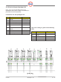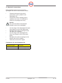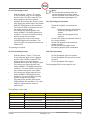
1
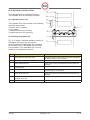
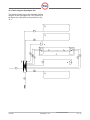
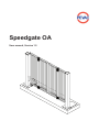
Speedgate OA
User manual, Version 1.5
© Pevac 06-2002
Nothing in this manual may be reproduced and/or published by means of print, photocopy,
microfilm or any other means whatsoever, without the prior permission of Pevac B.V.
This also applies for the associated illustrations.
07-2002
Speedgate - OA
en - 2
Pevac Speedgate OA
With the Speedgate OA, Pevac B.V. has
produced a high quality product for optimal
object and terrain security. A steel quick-folding
gate can open or close the entrance in only
a few seconds. When installed in the line of
fencing, the Speedgate OA ensures hermetic
sealing of incoming and outgoing gates. If
opened, there is no limitation in the traffics
height.
Declaration of agreement
The Speedgate OA is accompanied by a
manufacturer’s declaration.
With this, the product complies with the New
Approach guidelines, which guarantees optimal
safety. The declaration of conformance is
included at the back of this manual.
The Speedgate OA is hydraulically driven with a
special designed proportional unit.
The hydraulic drive is electrically operated.
There are a great number of possibilities for
operation, from simple, manual operation to
advanced entry control systems.
07-2002
Speedgate - OA
en - 3
Contents
1
USE OF THIS INSTALLATION
MANUAL
Related documents
Use according to destination
5
SAFETY
Safety and health risks
Safety precautions of the
Speedgate OA
Recommended environmental
safety provisions
Safety precautions and
maintenance
6
6
6
3
3.1
GUARANTEE
Liability
8
8
4
4.1
4.2
4.3
4.4
MACHINE DESCRIPTION
Technical data
Main components
Product identification
Principles of operation
9
10
13
14
14
5
OPERATION AND USE
15
6
PERIODIC INSPECTION BY OWN 15
PERSONAL
7
7.1
7.2
STORAGE AND TRANSPORT
Storage of the Speedgate OA
Transport of the Speedgate OA
16
16
16
8
8.1
8.2
8.3
8.4
8.5
8.6
8.7
17
17
17
17
18
18
18
19
8.8
8.9
8.10
8.11
INSTALLATION
Installation preparations
Installation conditions
Materials to be used
Preparing the foundation frame
Pit in asphalt or concrete
Pit in cobbled road
Placing the Speedgate OA
foundation
Fitting the jacked sleeves
Sealing the pit
Installation of the Speedgate OA
Installation of hoses and cables
9
9.1
9.2
9.3
HYDRAULIC SYSTEM
Hydraulic drive unit HB-OA
Hydraulic system
Hand pump system
21
21
21
22
1.1
1.2
2
2.1
2.2
2.3
2.4
07-2002
5
5
10
10.1
10.2
10.3
10.4
ELECTRICAL INSTALLATION
Hydraulic drive unit
Placing Speedgate OA
Cabling diagram Speedgate OA
Electrical diagram Speedgate OA
23
23
23
24
26
11
27
6
11.3
7
11.4
CONNECTION OF THE
SPEEDGATE OA
Electrical connections
Placing and connecting the
controller box
Bleeding air from the hydraulic
hoses
Hydraulic connections
12
12.1
12.1.1
12.1.2
12.1.3
12.1.4
12.2
12.2.1
12.2.2
12.3
12.4
COMMISSIONING
Adjusting the Speedgate OA
All wings in one line while closed
Height of the wings
Bending of the wings
Adjusting the top of the wings
Testing the functionality
Preventing access
Permitting access
Checking the operation
Final assembly
29
29
29
29
29
29
29
30
30
30
30
13
GENERAL INSPECTION AND
MAINTENANCE
Service intervals
31
32
14.1
THE SPEEDGATE OA AND THE
ENVIRONMENT
End of life spam
15
CE DECLARATION
33
11.1
11.2
13.1
14
27
27
27
28
31
32
19
19
19
20
Speedgate - OA
en - 4
1 USE OF THE INSTALLATION MANUAL
The manual is intended for persons who
are responsible for installing, operating and
maintaining the Speedgate OA. This manual
describes how the Speedgate OA can be safely
installed, used and maintained.
Read the manual completely before installing or
using the Speedgate OA.
Keep this manual in the control room.
In this manual the following pictograms and
symbols are used:
Warning
Danger of injury to operator or
bystanders, or danger of major damage
to the Speedgate OA or to other objects.
Follow the instructions carefully.
Danger
Life threatening danger or danger of
serious injury. Follow the instructions
carefully.
Note
Tip to make work easier.
1.1 Related documentation
As well as this manual for the Speedgate OA,
there are also the following documents:
- Maintenance book Speedgate OA.
- Log card.
- Parts book.
- Hydraulic drive unit manual.
- Controller manual.
1.2 Use according to destination
The Speedgate OA may NOT be used on a
public road. In terrains where the Speedgate
OA has been installed, a maximum speed of 30
km/hour must be observed.
The Speedgate OA may not be used for
moped riders, cyclists, motorcycle riders and
pedestrians.
The Speedgate OA can be used in the following
situations:
Environment
Remark regarding the environmental
impact of the Speedgate OA in
operation and of the Speedgate OA
should be disposed of.
Action
Actions to be taken.
This manual has been drafted with the utmost
care. Pevac B.V. is not liable for damage that
occurs as a result of any inaccuracies in this
manual. We request that you inform us, as a
matter of urgency, of any inaccuracies you may
find.
Security of amongst others:
- Industrial area’s
- Storage and cross-shipping
companies;
- Financial institutions;
- Auto(dealership) companies;
- Embassy’s
- Lease companies.
Any other or extended use does not comply
with the intended use. Use and install the
Speedgate OA only when it is in technically
perfect condition.
07-2002
Speedgate - OA
en - 5
2 SAFETY
In this chapter, the safety aspects of the Pevac
Speedgate OA are discussed.
Read this chapter thoroughly before use of the
Speedgate OA.
2.3 Recommended environmental safety
provisions
2.1 Safety and health risk
The Speedgate OA has been safely
constructed. At each installation in a certain
environment, new risks can occur that can be
different for each installation. The customer
must carefully assess beforehand what risks
can occur after the installation. In general the
following risks can be distinguished:
- Collision with the Speedgate OA due to
bad visibility;
- Collision due to excessive speed;
- Possible injury to moped riders,
cyclists, motorcycle riders and
pedestrians because they are too close
to the Speedgate OA.
During the design of the Speedgate OA, safety
precautions were taken to reduce these risks
as much as possible. By taking account of
the above risks and by following the safety
regulations, these risks are limited even more.
2.2 Safety precautions of the Speedgate OA
To make the use of the Speedgate OA as safe
as possible, the following safety measures have
been taken:
- To prevent the entrapment of body
parts, the Speedgate OA does not
have any protruding parts;
- To prevent the entrapment of body
parts, the Speedgate OA has as last
openings as possible;
- The opening of the Speedgate OA is
supplied with an photo-electric sensor
which detects is any object is inbetween the columns before closing;
- The wings of the Speedgate OA are
supplied with several safety edges, for
opening and closing;
07-2002
Speedgate - OA
Warning
Environmental measures must be
taken for the safe use of the Speedgate
OA. The necessary measures will be
different for each situation. In general
the following measures will contribute to
decreasing risks for road users.
Danger
The environment must be adapted in
such a way that a high speed (higher
than 30 km/hour) is hard to reach, for
example by bumps in the road surface,
an S-curve (with unobstructed
view) in the road and maximum speed
signs.
Danger
In order to ensure the safety of moped
riders, cyclists, motorcycle riders and
pedestrians, they must not be permitted
in the vicinity of the Speedgate OA. For
this group of road-users it’s necessary
to install a pedestrian-gate in the
surrounding area. Establishing a danger
zone with the help of traffic signs, text
signs, pictograms, road markings and
the physical separation of traffic flows
can facilitate this.
Warning
Traffic lights, warning boards, and
lighting should be placed in the vicinity
to insure good visibility of the Speedgate
OA.
Danger
If a traffic light is to be utilized, the green
light may only be given if the wings of
the Speedgate OA ore fully opened: this
indicates that the passage is completely
unobstructed. The traffic light must
change to red several seconds before
the Speedgate OA starts closing in order
to give road users sufficient time to stop.
The traffic light must remain red while
the Speedgate OA is moving and while it
is closed.
en - 6
Warning
It is forbidden to stop or to park inbetween the wings of the Speedgate
OA. Traffic signs can also indicate this.
Note
It is advisable to make recordings with
a security camera in the vicinity of the
Speedgate OA.
This has the advantage of providing
a record of a possible collision and
allowing a determination of the
possible cause. Furthermore, sabotage
can be witnessed and recorded.
Warning
The obstacle must not rise if vehicles are
in-between the wings of the Speedgate
OA. To this end, detection systems such
as detection strips in the road surface,
photocells, or cameras can be used.
Warning
Fault detection can be used. In the event
of a fault, the traffic light must change
to red and remain red. Additionally, in
that case, a signal must be sent to the
central control room.
2.4 Safety precautions and maintenance
•
•
•
•
•
07-2002
Check the Speedgate OA on every first
working day of the week for proper
functioning.
Check the visibility of the Speedgate OA
every first working day.
Carry out maintenance in accordance
with the specifications in the
maintenance and repair logbook.
During installation and maintenance
work, the drive must be disengaged.
The Speedgate OA can only be
operated by personnel who are
adequately trained and familiar with the
operation.
Speedgate - OA
en - 7
3 GUARANTEE
- The complaint is not immediately
reported to a qualified installer or
service organisation;
- Repairs are carried out without the
prior permission of Pevac BV;
- Parts are replaced without prior
permission from Pevac BV;
- Original parts are not used during
repair;
- The damage was caused by use other
than mentioned in § 1.2 “Use according
to intended purpose”;
- Claims do not take place within eight
days after the complaint was
discovered or reasonably should have
been discovered.
Guarantee is given according to the conditions
stated in the “Conditions of the Metal Union”.
Pevac BV, however, gives a guarantee for a
period of 24 months instead of 6 months, as
stated in 14.1 of the conditions of the metal
union. A copy of these conditions can be
obtained from Pevac BV.
The Speedgate OA has been manufactured
with the utmost care. Therefore, Pevac BV
gives the initial user a guarantee for 24 months,
taken from the invoice date.
The guarantee implies that Pevac BV makes
replacement parts available, free of charge, for
all parts that show any shortcomings, within the
term mentioned, due to imperfections of the
material or manufacture.
Excluded from guarantee are all parts
that should be replaced according to the
maintenance schedule and the safety edges.
The safety-edges always have to be send to
Pevac BV for inspection of the cause of the
failure.
The guarantee concerns the replacement of
defective parts, exclusive of installation, at the
discretion of Pevac BV.
Pevac BV explicitly rejects all further claims for
compensation of damage, of any nature.
The guarantee does not apply for faults that
have occurred due to injudicious, incorrect or
careless handling, incorrect use, incorrect
connection or connection by unqualified parties.
The guarantee expires if:
- Unauthorised parties have carried out
repairs or maintenance to the
installation;
- The installation was not used in
accordance with the normal
intended use or was used under
abnormal circumstances;
- It cannot be shown that the installation
was inspected by a qualified installer
or service organisation in accordance
with the maintenance schedule;
07-2002
The repair or replacement of parts during the
period of guarantee does not result in the
extension of this term. Replaced parts become
property of Pevac BV.
If necessary, Pevac BV can require that the
parts are shipped postage-paid to Pevac BV.
Postage-paid return is made if the repair was
carried out under guarantee.
Excluded from guarantee is all damage that
has occurred to the Speedgate OA by persons,
vehicles, or adjacent moveable or immovable
property.
3.1 Liability
Pevac BV accepts no liability for damage or
physical injury that occurs due to:
- Not following the instructions in this
manual;
- Carelessness during the use,
maintenance, repositioning, installing,
dismantling or repair of the Speedgate
OA;
- Use that is not in compliance with the
intended purpose.
Speedgate - OA
en - 8
4 MACHINE DESCRIPTION
The Speedgate OA consists of a steel frame
that is filled with concrete on site. In the
foundation are the connections for the jacket
sleeve and the drain tubes. These connections
are shown on drawing Fig. 4.1. The function of
the openings is mentioned in the table 4.1.
Connections of the foundation:
No Intended for
Function
A
Drain tube
Rain water drainage
connection to the sewer
B
Conduit
Feed-through for controller
cable and hydraulic
C
Hoisting
Feed-through hoisting straps or
chains
Table 4.1: Function of openings in foundation
Figure 4.1: Connections in foundation
On the foundation, two columns are installed,
with a drive-axle inside. Below the column,
inside the pits in the foundation, the hydraulic
cylinders are installed. The cylinders are
connected to the drive-axle. The outer wings
are mounted to the drive-axle. The inner wings
are mounted to the outer wings with hinges.
07-2002
Speedgate - OA
en - 9
4.1 Technical data
Figure 4.2 shows the standard dimensions of the Speedgate OA. The actual dimensions are
shown in the table below.
Sizes of Speedgate OA:
Type
A
B
C
D
E
2000 OA 2500
2500 mm
3450 mm
3700 mm
845 mm
2090 mm
2000 OA 3000
3000 mm
3950 mm
4200 mm
1095 mm
2090 mm
2000 OA 3500
3500 mm
4450 mm
4700 mm
1345 mm
2090 mm
2000 OA 4000
4000 mm
4950 mm
5200 mm
1595 mm
2090 mm
2000 OA 4500
4500 mm
5450 mm
5700 mm
1845 mm
2090 mm
2000 OA 5000
5000 mm
5950 mm
6200 mm
2095 mm
2090 mm
2000 OA 5500
5500 mm
6450 mm
6700 mm
2345 mm
2090 mm
2000 OA 6000
6000 mm
6950 mm
7200 mm
2595 mm
2090 mm
2000 OA 6500
6500 mm
7450 mm
7700 mm
2845 mm
2090 mm
2000 OA 7000
7000 mm
7950 mm
8200 mm
3095 mm
2090 mm
2500 OA 2500
2500 mm
3450 mm
3700 mm
845 mm
2590 mm
2500 OA 3000
3000 mm
3950 mm
4200 mm
1095 mm
2590 mm
2500 OA 3500
3500 mm
4450 mm
4700 mm
1345 mm
2590 mm
2500 OA 4000
4000 mm
4950 mm
5200 mm
1595 mm
2590 mm
2500 OA 4500
4500 mm
5450 mm
5700 mm
1845 mm
2590 mm
2500 OA 5000
5000 mm
5950 mm
6200 mm
2095 mm
2590 mm
2500 OA 5500
5500 mm
6450 mm
6700 mm
2345 mm
2590 mm
2500 OA 6000
6000 mm
6950 mm
7200 mm
2595 mm
2590 mm
2500 OA 6500
6500 mm
7450 mm
7700 mm
2845 mm
2590 mm
2500 OA 7000
7000 mm
7950 mm
8200 mm
3095 mm
2590 mm
3000 OA 2500
2500 mm
3450 mm
3700 mm
845 mm
3090 mm
3000 OA 3000
3000 mm
3950 mm
4200 mm
1095 mm
3090 mm
3000 OA 3500
3500 mm
4450 mm
4700 mm
1345 mm
3090 mm
3000 OA 4000
4000 mm
4950 mm
5200 mm
1595 mm
3090 mm
3000 OA 4500
4500 mm
5450 mm
5700 mm
1845 mm
3090 mm
3000 OA 5000
5000 mm
5950 mm
6200 mm
2095 mm
3090 mm
3000 OA 5500
5500 mm
6450 mm
6700 mm
2345 mm
3090 mm
3000 OA 6000
6000 mm
6950 mm
7200 mm
2595 mm
3090 mm
3000 OA 6500
6500 mm
7450 mm
7700 mm
2845 mm
3090 mm
3000 OA 7000
7000 mm
7950 mm
8200 mm
3095 mm
3090 mm
Table 4.2: Sizes of the Speedgate OA
07-2002
Speedgate - OA
en - 10
Figure 4.2: Over all dimmensions of the Speedgate OA
07-2002
Speedgate - OA
en - 11
Sizes and weights of foundation:
Type
A
B
C
Weight (with concrete)
XXXX OA 2500
3700 mm
1360 mm
400 mm
4800 kg
XXXX OA 3000
4200 mm
1360 mm
400 mm
5450 kg
XXXX OA 3500
4700 mm
1360 mm
400 mm
6100 kg
XXXX OA 4000
5200 mm
1360 mm
400 mm
6750 kg
XXXX OA 4500
5700 mm
1360 mm
400 mm
7400 kg
XXXX OA 5000
6200 mm
1360 mm
400 mm
8050 kg
XXXX OA 5500
6700 mm
1360 mm
400 mm
8700 kg
XXXX OA 6000
7200 mm
1360 mm
400 mm
9400 kg
XXXX OA 6500
7700 mm
1360 mm
400 mm
10050 kg
XXXX OA 7000
8200 mm
1360 mm
400 mm
10700 kg
Table 4.3: Sizes and weights of foundation.
Figure 4.3: Over all dimmensions of the foundation
Hydraulic cylinders:
Qty
Type
2
07-2002
Volume bottom side
40/25, stroke 300 mm
377 cc
Speedgate - OA
Volume piston side
230 cc
en - 12
4.2 Main components
Figure 4.4 shows the main components of the
Speedgate OA.
The Speedgate OA consists of the following
components:
1.
Foundation frame.
2.
Right column.
3.
Right outer wing.
4.
Right inner wing.
5.
Left inner wing.
6.
Left outer wing.
7.
Left column.
8.
Hinge.
9.
Guiding wheel.
10.
Top plate.
11.
Proximity switches and electrical
connection board.
Figure 4.4: Main parts of the Speedgate OA
07-2002
Speedgate - OA
en - 13
4.3 Product identification
The type plate shown in figure 4.5 contains the
following data:
1. Type number
2. Serial number
3. Year of construction
4. Weight
4.4 Principles of operation
According to the “fast open, fast close”
principle, two wings can fold to the left and
to the right hand side of the Speedgate. This
provides a dynamic blockade of the terrain.
Each wing is moved with a hydraulic cylinder to
block a passage or to make the passage free.
The arrow in the illustration (figure 4.6)
indicates the “attack side”.
Figure 4.5: Product Identification
Figure 4.6: Attack side of Speedgate OA
There are four proximity switches mounted in
the top of each column of the Speedgate OA.
This makes a total amount of eight proximity
switches. With the help of these switches, the
following positions can be detected.
Left wing open
Left wing almost open
Left wing almost closed
Left wing closed
Right wing open
Right wing almost open
Right wing almost closed
Right wing closed
07-2002
With the proximity switches it’s also possible to
detect a fault.
The Speedgate OA can be, depending on
the controller used, manually or automatically
operated.
Speedgate - OA
en - 14
5 OPERATION AND USE
Depending on the manner in which the
Speedgate OA is installed, a separate user
manual for operation may be applicable. See
the user manual included with the controller
system.
07-2002
6 PERIODIC INSPECTION BY OWN
PERSONAL
To guarantee the safety and the proper
functioning of the Speedgate OA maintenance
is necessary.
Every week the following actions must be taken:
•
Check the Speedgate OA for correct
functioning.
•
Check the visibility of the Speedgate
OA.
•
Remove dirt from the Speedgate OA.
•
Check that the guiding rail is clear.
Speedgate - OA
en - 15
7 STORAGE AND TRANSPORT
Warning
Ensure that for lifting work, the strength
of the hoisting belts or chains can handle
the weight to be hoisted. For the weight
of the foundation see the technical
specifications in chapter 4.
Warning
Ensure that the foundation of the
Speedgate OA hangs completely
horizontally and in balance during
hoisting.
Order of working when transporting the
foundation of the Speedgate OA:
Pull the 2 hoisting straps trough the
hoisting opening in the frame.
Hoist the foundation of the Speedgate
OA on the truck.
Place the foundation of the Speedgate
OA horizontally on the loading platform.
Fasten the foundation of the Speedgate
OA firmly on the truck, so that it cannot
slide in any direction during
transportation.
The same directions apply for unloading as for
loading.
7.1 Storage of the Speedgate OA
When storing the Speedgate OA, attention
should be paid to the following points:
- Place the Speedgate OA on a flat and stable
surface.
- Protect the Speedgate OA from dirt and
moisture.
- Prevent damage to the zinc coating by placing
the Speedgate OA on a wooden surface.
7.2 Transport of the Speedgate OA
Note
For the weight of the foundation, see
the technical specifications in
chapter 4.
Warning
Prevent damage to the powder coating
and the zinc layer during transport.
Warning
Position the Speedgate OA on a wooden
surface.
07-2002
Speedgate - OA
en - 16
8 INSTALLATION
8.1 Installation preparation
Note
The hydraulic drive unit must be
installed within a radius of 5 m from
one of the columns of the Speedgate
OA.
For successful installation you should prepare
yourself as follows:
Danger
During the installation (and also during
other work on the Speedgate OA), the
hydraulic drive unit should always be
switched off.
8.2 Installation conditions
Warning
The Speedgate OA can only be installed,
inspected, maintained and/ or repaired
by personnel who are qualified by Pevac
BV.
At the place of installation, the necessary
control cables and hoses must be present.
The hydraulic drive unit is mounted inside an
installation cabinet, together with the control
cabinet. A jacket sleeve for the cables and
hoses goes from the installation cabinet to the
one of the openings on the long sides of the
foundation of the Speedgate OA. Also check
drawing 4.1 and installation drawing fig. 8.1.
8.3 Materials to be used
For positioning the Speedgate OA, the following
equipment / tools are necessary:
- Crane truck.
- Hoisting belts or chains.
- Diamond saw (only for asphalt or concrete
hardening).
- Gravel and sand.
- Glass-fibre reinforced concrete.
- PVC jacket sleeve with connectors (ø 100
mm) for the hydraulic hoses and the
electrical cable.
- Pull cord, to pull the cables and hoses
through the jacket sleeve.
- PVC drain tube with sleeves (ø 100 mm) for
the drainage of rainwater (if connection to
the sewer is possible).
- Electrical connection (in the control room)
with main switch.
Depending on the road surface in which the
Speedgate OA must be installed, it will be
necessary, in accordance with the installation to
make a pit and a trench in the road surface in:
- Asphalt hardening (see § 8.4), or
- Cobbled road (see § 8.5).
Figure 8.1: Standard configuration
07-2002
Speedgate - OA
en - 17
8.4 Preparing the foundation frame
8.5 Pit in asphalt or concrete
For the largest versions of the Speedgate OA,
the foundation frame exists in two parts. These
parts have to be mounted together on site.
•
•
If necessary, mount the parts of the
Speedgate OA foundation frame
together.
Put some steel reinforcement in
from one part to the other. Make sure
the reinforcement is in both parts at the
same time.
Put the foundation frame on a smooth
and flat surface.
Fill the frame with concrete. Use a
needle-shaker machine to make sure
the concrete is sealed well.
Leave the foundation to dry according
the guidelines of the concrete
manufacturer.
•
•
•
•
•
•
•
8.6 Pit in cobbled road
•
•
•
Mark off the location on the road surface
where the Speedgate OA should be
positioned and where the jacket sleeve
must be placed (see fig. 8.2). The sizes\
of the pit and the groove for the jacket
sleeve are given in the following tables.
Remove the cobbles at that location.
Dig the pit for the Speedgate OA and
the groove for the jacket sleeve
sufficiently deep.
Note
The length of the groove depends on
the distance between the pit and the
control room. The maximum distance
is 5 m.
Pit sizes:
Type
Mark off the location on the road surface
where the Speedgate OA should be
positioned and where the jacket sleeve
must be placed (see fig. 8.2). The sizes
of the pit and the groove for the jacket
sleeve are given in the following tables.
Cut into the asphalt a few centimetres
with a diamond saw (see also fig. 8.2).
Dig away the asphalt in front of the
Speedgate OA as well as in front of the
jacket sleeve.
Dig the pit for the Speedgate OA and
the groove for the jacket sleeve
sufficiently deep.
Length
Width
Dept
XXXX OA 2500
4300 mm
1900 mm
500 - 600 mm
XXXX OA 3000
4800 mm
1900 mm
500 - 600 mm
XXXX OA 3000
5300 mm
1900 mm
500 - 600 mm
XXXX OA 3000
5800 mm
1900 mm
500 - 600 mm
XXXX OA 3000
6300 mm
1900 mm
500 - 600 mm
XXXX OA 3000
6800 mm
1900 mm
500 - 600 mm
XXXX OA 3000
7300 mm
1900 mm
500 - 600 mm
XXXX OA 3000
7800 mm
1900 mm
500 - 600 mm
XXXX OA 3000
8300 mm
1900 mm
500 - 600 mm
XXXX OA 3000
8800mm
1900 mm
500 - 600 mm
-
250 mm
700 - 800 mm
GROVE
07-2002
Speedgate - OA
en - 18
8.7 Placing Speedgate OA foundation
8.9 Sealing the pit
•
•
•
•
•
•
Fit road cloth at the bottom of the pit
(see fig. 8.3).
Pour about 20 cm of sand in the pit and
flatten it out.
Pull the hoisting straps trough the
hoisting openings of the foundation.
(see chapter 4)
Position the foundation in the pit so that:
- It is completely level.
- The top of the foundation is levelled
with the road surface.
Remove the hoisting straps.
•
•
•
Fill up the space surrounding the
Speedgate OA with glass-fibre
reinforced concrete, in accordance with
the concrete supplier’s specifications.
Smoothen the surface of the concrete.
In the case of a cobblestone road, cover
the opening above the concrete with
previously removed cobblestones.
Leave the concrete to harden.
Note
Put the cobblestones in the
concrete. Do not use sand under the
cobblestones.
8.10 Installation of the Speedgate OA
•
•
•
8.8 Fitting the jacket sleeves
•
Warning
Do not use 90º bends in the corners of
the jacket sleeve for the feed-through of
the hydraulic hoses.
•
•
•
07-2002
•
Install the large bearings on the bottom
of the steel pits in the foundation
frame. Make sure that the grease-nipple
points towards the top-plate. One
bearing in each pit.
Put the column on top of the foundation
and insert the drive-axle in to the large
bearing on the bottom. The drive-axle is
already inside the column. Make sure
that both hedges are between the
columns.
Level the columns and make sure that
they are exact vertically.
Mount the wings on the drive-axle.
Put the cable of the safety-edges trough
the openings to it can’t be damaged.
Insert the hydraulic mechanism in the
pit and connect it on both sides.
Put the jacket sleeve in the groove,
pass one end through the cable opening
in the long side of the foundation and
the other end in the wall feed-through in
the base of the installation cabinet.
Feed the pull cord through the jacket
sleeve.
Fit the drain tube for rain water drainage
and connect it to the sewer at the
openings in both short sides of the
foundation.
Speedgate - OA
en - 19
8.11 Installation of hoses and cables
•
•
•
Pull the four hydraulic hoses and the
two electrical cables through the jacket
sleeve. Use the pull cord in the jacket
sleeve for this purpose.
- Be certain that the hydraulic hoses in
the Speedgate OA are sufficiently
long.
- Be certain that the cables in the
Speedgate OA are sufficiently long.
Pull the two longest hoses to the other
pit trough the conduit that’s inside the
frame.
Pull one cable to the other pit trough the
conduit that’s inside the frame.
Note
Be certain that there are no kinks in the
hydraulic hoses or the cable.
07-2002
Speedgate - OA
en - 20
9 HYDRAULIC SYSTEM
9.1 Hydraulic drive unit HB-OA
The Speedgate OA is driven by a special
designed proportional hydraulic unit HB-OA.
This unit is capable of driving one Speedgate
with two wings. The speed of the wings is
electronically detected and hydraulically
adjusted.
The hydraulic unit has the following
specifications.
Details hydraulic unit HB-OA:
Maximum
working
pressure
Pump
capacity
Tank
capacity
100 bar
11 cc / revolution
50 litre
For operation of the Speedgate OA, the
hydraulic unit is equipped with electricallyoperated proportional hydraulic valves for
opening and closing. There is one valve for
each wing.
For operation of the hydraulic drive unit see the
manufacturer’s directions.
9.2 Hydraulic system
The drawing below shows the hydraulic
diagram of the hydraulic unit HB-OA. The
components shown in the hydraulic diagram
are mounted on the hydraulic drive unit or on
the Speedgate OA. The table on the next page
shows which components are used.
Electrical details hydraulic unit HB-OA:
Motor power
Motor voltage
3 kW
400 VAC (3 phase)
07-2002
Speedgate - OA
en - 21
Standard components used on the hydraulic
unit HB-OA:
Pos. Description
1.
Hand pump
2.
Electric motor (3 phase)
3.
Gear pump
4.
Pressure filter
5.
Tank level indicator
6.
Oil tank
7.
Level switch
8.
Fill cap with filter
9.
Proportional valve unit with pressure protector system
10.
Hand pump valve
11.
Double return valve
12.
Return filter
13.
Quick coupler Female
14.
Quick coupler Male
15.
Hoses with Male and Female Quick coupler
16.
Cylinder
17.
Manometer with manometer valve
9.3 Hand pump system
Open Speedgate:
If the controller gives the command ‘Open
Speedgate’, the gear pump (3) begins to
turn, through which the hydraulic oil becomes
pressurized. As result, both proportional valves
(9) are opened slightly, through which the top
side (or rod side) of the cylinders (17) comes
under pressure and the cylinders are driven
inward. As result, the return valve (11) comes
under pressure, through which it is opened
and the oil, located on the bottom-side of the
cylinders, flows back to the reservoir. Once
the wings start moving, a sensor detects this
condition and the valves (9) are opened more.
This speeds up the Speedgate OA. When
the wings are almost open, this condition is
detected by another sensor and the valves (9)
are closing a little. The speed of the wings is
getting lower. When the wings has reached the
end position, again this condition is detected
and the valves (9) are closing and the pump
(11) is switched off.
07-2002
Close Speedgate:
If the controller gives the command ‘Close
Speedgate’, the gear pump (3) begins to
turn, through which the hydraulic oil becomes
pressurized. As result, both proportional valves
(9) are opened slightly, through which the
under side (or bottom side) of the cylinders
(17) comes under pressure and the cylinders
are driven outwards. The wings start closing.
As result, the return valve (11) comes under
pressure, through which it is opened and the
oil, located on the top-side of the cylinders (or
rod side), flows back to the reservoir. Once
the wings start moving, a sensor detects this
condition and the valves (9) are opened more.
This speeds up the Speedgate OA. When
the wings are almost closed, this condition is
detected by another sensor and the valves (9)
are closing a little. The speed of the wings is
getting lower. When the wings has reached the
end position, again this condition is detected
and the valves (9) are closing and the pump
(11) is switched off.
The hydraulic drive unit HB-OA is equipped with
a hand pump system. The hand pump system
makes it possible to operate the wings of the
Speedgate OA with this hand pump in case of a
power failure.
Note:
In order to operate the pump, a tube is slid in
the pump.
To move the obstacle up and down, the hand
pump valve (10) must be manually set in the
correct position. Now the hand pump (1) can be
operated so that the wings can be opened or
closed. Each wing has a separate hand pump
system.
Speedgate - OA
en - 22
10 ELECTRICAL INSTALLATION
The Speedgate OA is hydraulically driven.
The hydraulic drive is electrically operated.
10.1 Hydraulic drive unit
The hydraulic drive unit consists of the following
electrical components:
• Electric motor (3 phase)
• Level switch
• proportional valve for left wing
• proportional valve for right wing
10.2 Placing Speedgate OA
Fig. 10.1 shows a standard situation in which a
Speedgate OA can be put into service.
In this situation, the Speedgate OA is suitable
for two-way traffic. Traffic lights are also used
in this situation. The installation can, in most
situations, be adapted as desired.
Pos. Description
Function
A.
Open detection loop (auto exit)
Automatic drive-out (auto-exit) Opens the Speedgate
OA automatically in one direction.
B.
Driveway
C.
Safety detection loop
D
Speedgate OA
E.
Traffic light
Warning if the Speedgate OA is not completely open:
Drive-through is not possible!
F.
Safety detection loop
Safety while closing and Automatic closing after the
passage
G.
Installation cabinet with controller and
hydraulic drive unit.
Control of the Speedgate OA.
H.
Push-button console
Operation of the Speedgate OA.
07-2002
Safety while closing and Automatic closing after the
passage
Speedgate - OA
en - 23
10.3 Cable diagram Speedgate OA
The drawing below shows the standard cabling
diagram of the Speedgate OA. The positions in
the figure are equivalent to the positions in fig.
10.1.
07-2002
Speedgate - OA
en - 24
Cables and hoses for Speedgate OA controller from fig. 10.1:
Pos. Cable type
From
To
Function
1.
Power cable - armoured, with tinner
copper ground, 2,5mm (12 AWG)
Power Supply
Controller
3 phase + neutral +
ground
2.
Signal cable - armoured and shielded, 5 twisted pairs, 0,8mm (18
AWG)
Controller
Push button console
Operation
3.
Hydraulic hose 3/8”
Hydraulic unit
Speedgate OA
Open left wing
Hydraulic hose 3/8”
Hydraulic unit
Speedgate OA
Close left wing
Hydraulic hose 3/8”
Hydraulic unit
Speedgate OA
Open right wing
Hydraulic hose 3/8”
Hydraulic unit
Speedgate OA
Close right wing
Signal cable - armoured and shielded, 4 twisted pairs, 0,8mm (18
AWG)
Controller
Speedgate OA
Sensors left column
Signal cable - armoured and shielded, 4 twisted pairs, 0,8mm (18
AWG)
Controller
Speedgate OA
Sensors right column
4.
Power cable - armoured, with tinned
copper ground wire, 3 conductors,
1,5mm (14 AWG)
Controller
Traffic light
Red / Green
5.
Power cable - armoured, with tinned
copper ground wire, 3 conductors,
1,5mm (14 AWG)
Controller
Traffic light
Red / green
6.
Signal cable - armoured and shielded, 1 twisted pair, 0,8mm (18
AWG)
Controller
Detection loop
Detection loop safety
7.
Signal cable - armoured and shielded, 1 twisted pair, 0,8mm (18
AWG)
Controller
Detection loop
Detection loop safety
8.
Signal cable - armoured and shielded, 1 twisted pair, 0,8mm (18
AWG)
Controller
Detection loop
Auto Exit
07-2002
Speedgate - OA
en - 25
10.4 Electrical diagram Speedgate OA
In fig. 10.3, the electrical diagram for the
Speedgate OA is given. Figure 10.4 shows the
print layout for the connections.
Connections for the Speedgate OA:
Pos. Function
Label on print
X1
Control
CONTROLLER
X2
Control
CTRL
X3
Limit switch open
OPEN
X4
Limit switch almost open ALM OPEN
X5
Photo electric transmitter
TRANSM
X6
Limit switch almost
closed
ALM CL
X7
Limit switch closed
CLOSED
X8
Photo electric receiver
RECEIVER
Code
Wire colour
X9
Safety edges
SAFETY
BU
Blue
BN
Brown
BK
Black
WT
White
The colour coding is given in the following
table:
RD
07-2002
Speedgate - OA
LED colour
Red
en - 26
11 CONNECTION OF THE SPEEDGATE OA
Warning
Ensure that the oil tank is always full.
This chapter describes how the Speedgate OA
should be connected electrically and
hydraulically.
11.1 Electrical connections
•
Connect the controller cable to
connection strip ‘X1’ of the Speedgate
OA according to the table below. (see
fig. 10.3). Thereafter, check the
connections carefully.
Note
For air bleeding, see also the user
manual for the hydraulic drive unit.
•
•
Connect the hydraulic hoses in the
Speedgate OA to one another.
Connect the outlets of the hydraulic
drive unit together.
Careful
The hydraulic hoses supplied by Pevac
are already filled with hydraulic oil. For
this reason fasten the hoses well, so that
no oil can escape from the hoses, which
would cause difficulty in the bleeding of
air.
Terminal Function
1
Feed voltage + 24 VDC
2
Ground
3
Wing open (contact proximity switch)
4
Wing almost open (contact proximity
switch)
5
Wing almost closed (contact proximity
switch)
6
Wing closed (contact proximity switch)
7
Photo sensor in
8
Photo sensor blocked (contact photo
electric sensor)
•
•
11.2 Placing and connecting the controller
box
•
•
•
The placement and connection of the
controllers and the push button panel is
dependant on the chosen installation and the
control. The installation thereof is given in the
accompanying documentation.
Open the valve of one of the hand
pumps.
Use the hand pump for several minutes
so that all the air is forced out of the
hoses.
Open the valve of the other hand pump.
Use the second hand pump for several
minutes so that all the air is forced out of
the hoses.
Loosen the hoses of the Speedgate OA
from one another.
- In order to detach the hoses,
the ring of the quick-coupling
must be retracted.
11.3 Bleeding air from the hydraulic hoses
Danger
•
During connection of the
hydraulic hoses, the hoses
MUST NOT be under pressure.
•
The electrical mains power must
be switched off.
Warning
When working with hydraulic systems
be extremely clean: sand and other
contaminants can lead to failures and
excessive wear of the system.
07-2002
Speedgate - OA
en - 27
11.4 Hydraulic connections
If the hydraulic hoses are free of air, the
Speedgate OA can be connected as follows:
•
Connect the hoses to the quickconnectors on the cylinder in the
Speedgate OA.
Loosen the swivel couplings on the
cylinders (as a rule, it is sufficient to
loosen the couplings two turns).
•
Careful
The screw threads in the hydraulic
cylinders must not be damaged!
•
Let the wings of the Speedgate OA open
very slowly by use of the hand pump.
Re-tighten the swivel couplings on the
rod side of the cylinders.
Let the wings of the Speedgate OA
close very slowly by use of the hand
pump.
Re-tighten the swivel couplings on the
bottom side of the cylinders.
Check the oil level once again.
•
•
•
•
Connections for the Speedgate OA:
Connector type
Function
Male
Open the wing
Female
Close the wing
07-2002
Speedgate - OA
en - 28
12 COMMISSIONING
•
12.1 Adjusting the Speedgate
•
Danger
Before the Speedgate OA is tested:
- There can be no cars on or in
the vicinity of the Speedgate
OA;
- The Speedgate OA must be
cleared of obstacles, such as
materials that have been used
for the assembly;
- Personnel must be out of the
vicinity of the Speedgate OA.
12.1.1 All wings in one line while closed
Check if the wings are in one line when closed
hydraulically. If the wings are bended, the
hydraulic cylinder has to be adjusted. The
following steps have to be taken:
•
•
•
Un-tighten the four bolds of the cylinder
bracket on the bottom side.
Adjust the cylinder by the centre-bold
until the wings are in one line.
Tighten and lock the bolds.
12.1.2 Height of the wings
Tighten and lock the bolds of the
bearing.
If necessary the large bearing can also
be adjusted.
12.1.4 Adjusting the top of the wings
Check if the wings are in one line when closed.
Make sure that one of the wings is not bended
to the inside or the outside. If the wings are
not in one line, the following steps have to be
taken:
•
•
•
•
Un-tighten the bolds of the top bearing
inside the column.
Force the drive axle to the inside or
outside until the wings are in one line.
Tighten and lock the bolds of the
bearing.
If necessary the large bearing can also
be adjusted.
12.2 Testing the functionality
In the following description, the functions of the
valves and proximity switches refer to
their functions. The names that are used, are
shown in the table below.
The operation/functioning of the Speedgate OA
is as follows:
Check if the wings of the Speedgate are on the
same level. If one of the wings is lower than the
other, the following steps have to be taken:
•
•
•
Un-tighten the ring of the bearing on the
bottom of the pit.
Lift the lowest wing so it’s as high as the
other wing.
Tighten and lock the ring on the large
bearing.
12.1.3 Bending of the wings
Check if the wings are bending down to the
concrete foundation in the closed position. If so,
the following steps have to be taken:
•
•
07-2002
Un-tighten the bolds of the top bearing
inside the column.
Force the drive axle to left or right until
the wings are horizontally.
Speedgate - OA
en - 29
12.2.1 Preventing access
•
Push the button: “Close”: The motor
of the hydraulic drive unit is engaged
and the valve CLOSE is opened. This
allows pressure into the hydraulic
cylinders that causes the wings to close
If the wings are almost open, limit switch
ALMOST OPEN detects this condition.
The valve CLOSE is opened more and
the wings will move faster.
If the wings are almost closed, limit
switch ALMOST CLOSED detects this
condition. The valve CLOSE is closing
and the wings will slow down.
If the wings are closed, limit switch
CLOSED detects this condition. The
valve CLOSE is closed and the motor is
switched off.
•
•
•
The passage is closed.
Note:
For the specific operation and the
customer adapted controller panel,
see the separate user manual for the
customer adapted Speedgate OA.
12.3 Checking the operation
•
•
•
•
Check all hydraulic connections for
leaks:
- During movement of the wings;
- When the Speedgate OA is
closed;
- When the Speedgate OA is
opened.
Check if the proximity switches detect in
the correct position.
Check if all signals of the electronic
system function.
Check that the Speedgate OA is
functioning properly after installation.
12.2.2 Permitting access
12.4 Final assembly
•
•
•
Push the button: “Open”: The motor
of the hydraulic drive unit is engaged
and the valve OPEN is opened. This
allows pressure into the hydraulic
cylinders that causes the wings to open.
If the wings are almost closed, limit
switch ALMOST CLOSED detects this
condition. The valve OPEN is opened
more and the wings will move faster.
If the wings are almost opened, limit
switch ALMOST OPEN detects this
condition. The valve OPEN is closing
and the wings will slow down.
If the wings are opened, limit switch
OPEN detects this condition. The valve
OPEN is closed and the motor is
switched off.
•
•
•
•
Fit the Speedgate OA cover plates.
Fit the Speedgate OA top covers on the
columns.
Fit the Speedgate OA hedges.
The Speedgate OA is now ready for use.
The passage is now clear.
Type of detector
Name
Function
Proximity switch
Limit switch open
Detects open position of the wing
Limit switch almost open
Detects almost open position of the wing
Limit switch almost closed
Detects almost closed position of the wing
Limit switch closed
Detects closed position of the wing
Valve open
Opening the wing
Valve close
Closing the wing
Valve
Table 11.4: Name of sensors
07-2002
Speedgate - OA
en - 30
13 GENERAL INSPECTION AND
MAINTENANCE
Warning
• When working on the Speedgate OA,
disconnect the mains power!
• When working on the Speedgate OA,
close off the hydraulic pressure.
To guarantee the safety and the proper
functioning of the Speedgate OA, maintenance
by Pevac B.V. qualified personnel is necessary.
Note
See the Pevac B.V. maintenance book
for the first maintenance.
13.1 Service intervals
For the first time:
A month after installation.
After that:
Three months after installation.
Consequently every:
Six months.
Work to be carried out:
- General visual check.
- Cleaning the Speedgate OA and the
mechanism.
- Lubrication of the cylinder eyes.
- Checking the attachment of bolts and
nuts, specifically those of turning
elements.
- Checking the hinges of the wings for
play and, as necessary, replacing the
plastic coating.
- Updating the Pevac B.V. log card. On
this card, the corrective measures
should also be recorded.
- If the log card is full, please send it to
Pevac BV in Zevenhuizen. You will
then receive a new log card by return
mail.
07-2002
Speedgate - OA
en - 31
14 THE SPEEDGATE OA AND THE
ENVIRONMENT
Through the use of biodegradable hydraulic oil,
the environmental impact can be reduced.
Take care, nonetheless, that in the case of
leakage the oil cannot enter the environment
directly. The use of an oil-leak pan in the
installation cabinet can prevent this from
occurring.
The installed hydraulic drive is equipped with an
electronic level detector. This allows early
detection of any possible leakage so that
measures can be taken in a timely manner.
In addition, the hydraulic tank is provided with a
sight glass. This permits checking of
the oil level.
14.1 End of life span
The Pevac B.V. Speedgate OA can have a
technical life span of 15 years under normal
circumstances, with normal use and good
maintenance.
Environment
At the end of the life span the Terrain
Blocker TB should be disposed of as
follows.
Part
Manner of processing
Foundation frame
Scrap
Columns
Scrap
Wings
Scrap
Hydraulic drive unit
Revision
Hydraulic oil
Chemical waste
Plastic parts
Container for plastic
Electrical components
Special recycling companies
Remains
Scrap
07-2002
Speedgate - OA
en - 32
15 CE DECLARATION
EC DECLARATION OF CONFORMITY
(according to annex II A of the machine guideline)
We,
Pevac BV
Nijverheidscentrum 6, Zevenhuizen,
The Netherlands,
declare totally under own responsibility, that the products:
Speedgate
2000 OA 2500,
2000 OA 3000,
2000 OA 3500,
2000 OA 4000,
2000 OA 4500,
2000 OA 5000,
2000 OA 5500,
2000 OA 6000,
2000 OA 6500,
2000 OA 7000,
2500 OA 2500,
2500 OA 3000,
2500 OA 3500,
2500 OA 4000,
2500 OA 4500,
2500 OA 5000,
2500 OA 5500,
2500 OA 6000,
2500 OA 6500,
2500 OA 7000,
3000 OA 2500
3000 OA 3000
3000 OA 3500
3000 OA 4000
3000 OA 4500
3000 OA 5000
3000 OA 5500
3000 OA 6000
3000 OA 6500
3000 OA 7000
which this declaration concerns, are in accordance with the following standards:
•
•
•
NEN-EN 292-1 en NEN-EN 292-2; 1996
NEN-EN 60204; 1995
NEN-EN 4413; 1998
Safety of machines (basis concepts)
electrical equipment of machines
General rules for hydraulic systems
according to the determinations of:
•
the machine guideline 89/392/EEG, amended by guidelines 91/368/EEG, 93/44/EEG,
93/68/EEG
G. Slotman
Director
The Netherlands, Zevenhuizen, July 2002
07-2002
Speedgate - OA
en - 33