1
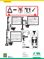
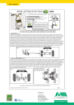
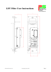
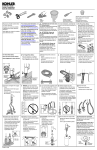
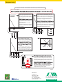
Brugsanvisning
FITTING THE ‘RIDE ON’ ATTACHMENT TO THE ATV (ALL TERRAIN VEHICLE)
IMPORTANT:
***
for the clamp screws, avoiding obvious obstructions wherever possible.
Slide into position
Slide the bracket onto the vehicle
in the required position( forward
of the seat, with the top plate of
the clamp squarelyon the footplate)
and hold in place.
Push the unthreaded part of the screws
though the holes in the bottom plate and
place the clamp head (C) on the top of the
screw to check that it is in a suitable position,
then remove. Push the screw until the
threaded part engages with the threaded
hole, and turn the screw in a clockwise
on the bottom plate to determine
the optimum location to avoid any
chassis obstacles.
Use as many screws as needed,
(a minimum of four) to spread the
load of the clamp over the largest
area possible.
spring washer (A) and locking nut (B) onto the
screw. Repeat this with all the screws
required to secure. Replace the clamp heads
and hand tighten the screws, in rotation, until
all the clamp heads are touching the
underside of the foot plate.
A
C
A
B
B
C
Using a suitable 19mm ratchet
spanner / wrench, gradually tighten
the screws, working in a systematic
pattern to avoid any possibility of
1
3
5
NOT fully tighten screws individually,
to a vehicle)
When the bracket is fully secured,
tighten the locking nuts against the
spring washers to ensure that the
screws do not work loose during use.
4
2
Example of screw tightening sequence
should be in a vertical position with the top
plate square on the foot plate of the vehicle.
It should be positioned as near as possible to
the seat, allowing the operator to reach the
power switch without undue stretching
SEAT
CLAMP IN POSITION ON VEHICLE
into the foot plate, using the top plate of the
bracket as a template, taking care not to
compromise any chassis parts.
Page 1
Distribution:
E. Marker A/S
Okslundvej 8, Bov
DK-6330 Padborg
Tlf.: +45 74 67 08 08
E-mail: [email protected]
www.emarker.dk
www.emarker.dk
Brugsanvisning
14kg +
x2
x1
CAUTION! RISK OF TRAPPING FINGERS IN MOVING PARTS, DURING ASSEMBLY
fig 7 To ensure the correct working
fig 6 *** Fitting the attachment is a
b
two person operation.
Offer the attachment to the
bracket, and locate up to 3 screws
through the backing plate, into the
slots in the bracket. Place the nuts
and washers onto the screws and
hand tighten until the final working
position is determined.
c
a
c
fig 8 When the attachment is fitted to the
required height, tighten the screws
fully.
When manoeuvering on the pitch or
field, it is not necessary to fit the
retaining pin and lynch pin, the unit
will stay in the ‘UP’ position with the
tension of the springs only.
For moving from site to site, secure
with the retaining pin d and lynch
pin b to prevent accidental release
of the attachment during transport.
position, hand tighten the nuts a
and release the lynch pin ( b fig 6 )
securing the retaining pin ( d fig 9), to
allow the attachment to lower to ground
level.At this level, the arms of the
attachment c should be in a position
lower than horizontal, as shown. if this is
not the case, secure the arms again and
adjust the attachment position higher
on the bracket and re-tighten.
FITTINGS SUPPLIED
fig 9
d RETAINING PIN x1
x2
b LYNCH PIN x3
x4
30mm x M12
x5
Line width
adjustment plates
to adjust spray width,
from 4” to 3”
(75 to 100mm approx’)
120mm x M12
x5
a
M12
x10
NUTS
Fit in position
here on
both sides
of spray ‘shoe’
x12
M12
WASHERS
M12
x10
SPRING WASHERS
Auxiliary cable (2mtrs)
Pipe work extension
Page 2
Distribution:
E. Marker A/S
Okslundvej 8, Bov
DK-6330 Padborg
Tlf.: +45 74 67 08 08
E-mail: [email protected]
www.emarker.dk
www.emarker.dk
Brugsanvisning
CONNECTING THE EQUIPMENT PRIOR TO SPRAYING
The next stage is to make the necessary connections
to allow the spraying operation to take place.
STEP 1:
Connect the 2 sets of cables from the spray head
tube near the switch, to the extension cables. One of
the cables is colour coded to avoid errors in
connecting. There is an option to connect the power
unit direct to the battery on the vehicle. To do this,
use the auxiliary cable with the twin forked battery
connectors, and connection box plug connector.
Connect the cable to the battery using the forked
connectors first, then plug into the connection box.
Ensure the machine is turned OFF when connecting.
Step 2:
Connect the length of extension pipe work using the
black plastic push-fit adaptor supplied. Ensure that
the pipe work is inserted firmly into the adaptor and
the spray head outlet on the pump.
Check that all the connections are correct by
turning the machine on, using the switch at the
top of the spray head tube.
fig 10
Spray
Attachment
Power Unit
The spray head tube
The spray head tube is
complete and requires no
additional assembly. It can be
detached from the square tube
by lifting upwards slightly to
clear the height stop B, and
pulling forward out of the
plastic clips A. This will be
useful when marking
penalty spots and
corner quadrants.
A
Do not over-reach
with the tube causing
electrical connections
to dislodge or become
damaged. To prevent
this problem if used A
regularly, detach the
B
switch cable from the
other cables, and
refasten the remaining cables.
SPRAYING PAINT AND CLEANING THE RIDE ON EQUIPMENT
THE ATTACHMENT SHOULD BE IN THE FULLY DOWN POSITION WHEN THE SPRAYING OPERATION COMMENCES
Paint Filter
fig 11
FROM THE
PAINT
CONTAINER
TO THE SPRAYHEAD
BATTERY COVER
Position 1
1
Position 2
No Filter
FROM THE
WATER
CONTAINER
+
PUMP
Spraying Paint:
To spray paint through the system, it is important to
ensure that the valve tap 1 is in the correct position
to draw the paint from the container. The paint probe
is fitted with a filter, and should not be used for the
water delivery at this stage. The valve tap should be
positioned so that it is in line with the paint tube as
shown in fig 11 position 1. Switch on the machine
using the switch on the top of the attachment, to start
the paint flow. As soon as the paint flows freely from
the spray head, spraying can begin. At any time
during the spraying operation, the flow can be
stopped or started using the switch.
To avoid any drying out of paint on the nozzle during
hot or warm weather, when moving from one
pitch / field to another pitch / field, move the valve
tap to position 2 and turn the switch on, to allow
water to flush through the spray nozzle. Then return
to position 1 to return to spraying paint.
Cleaning the Ride On:
To thoroughly clean the Ride On at the end of the day, place the paint delivery probe into the water container,
and turn on the machine. This will allow water to clean the paint probe and filter, the pump and the spray head.
Only perform this operation in an area which will not be affected by the paint in the system that will be
discharged onto the ground. Run water through the system until the spray from the nozzle is clear, or evident
that the system has been cleaned. Replace the cap on the paint container to avoid any spillage during the
transporting of the vehicle back to the storage area. (When familiar with the machines performance, it is
possible to move the paint probe to the water container, turning the valve tap to position 2, before
completing the last part of the marking out operation. This will use the paint already in the system to
complete the marking, before water starts to be dispensed through the spray nozzle. Experience will
determine the distance that can be covered by the remaining paint)
Page 3
Distribution:
E. Marker A/S
Okslundvej 8, Bov
DK-6330 Padborg
Tlf.: +45 74 67 08 08
E-mail: [email protected]
www.emarker.dk
www.emarker.dk