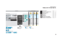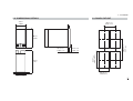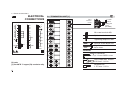
1
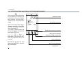
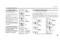
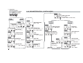
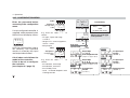
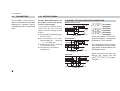
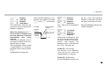
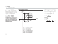
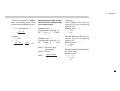
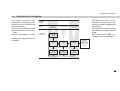
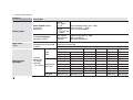
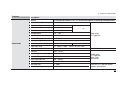
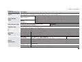
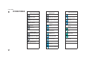
Double action controller
with analogue output
1/ DIN - 48 x 96
8
ASCON spa
ISO 9001
C e r t i f i e d
ASCON spa
20021 Bollate
(Milan) Italy
via Falzarego, 9/11
Tel. +39 02 333 371
Fax +39 02 350 4243
http://www.ascon.it
e-mail [email protected]
c
X3 line
User
Manual
•
M.I.U.X3
-4/04.02 •
Cod.
J30-478-1AX3
C
I E
UL
LISTED
US
Double action controller
with analogue output
1/ DIN - 48 x 96
8
c
X3 line
C
X3
I1 I2 I3
45.80
45.80
UL
LISTED
US
Information
c
NOTES
ON ELECTRIC
SAFETY AND
ELECTROMAGNETIC
COMPATIBILITY
Please, read carefully these instructions before proceeding with the installation of
the controller.
Class II instrument, real panel mounting.
This controller has been designed with compliance to:
Regulations on electrical apparatus (appliance, systems and installations) according to
the European Community directive 73/23/EEC amended by the European Comunity directive 93/68/EEC and the Regulations on the essential protection requirements in electrical
apparatus EN61010-1 : 93 + A2:95.
Regulations on Electromagnetic Compatibility according to the European Community
directive n089/336/EEC, amended by the European Community directive n° 92/31/EEC,
93/68/EEC, 98/13/EEC and the following regulations:
Regulations on RF emissions
EN61000-6-3 : 2001
residential environments
EN61000-6-4 : 2001
industrial environments
Regulation on RF immunity
EN61000-6-2 : 2001
industrial equipment and system
It is important to understand that it’s responsibility of the installer to ensure the compliance
of the regulations on safety requirements and EMC.
The device has no user serviceable parts and requires special equipment and specialised
engineers. Therefore, a repair can be hardly carried on directly by the user. For this purpose,
the manufacturer provides technical assistance and the repair service for its Customers.
Please, contact your nearest Agent for further information.
All the information and warnings about safety and electromagnetic compatibility are
marked with the B sign, at the side of the note.
2
Table of contents
TABLE OF CONTENTS
Operating mode
Resources
Control
Alarms
Retransmission
Main universal input
PV / SP
12
OP1
PV
1
OP2
Auxiliary input
AUX
OP3
(Option)
Digital input
IL1
IL2
IL3
OP4
OP2 OP3 OP5
Single
2 action
3
OP4
OP1 OP2 OP3 OP5
OP5
OP1 OP2 OP3
4
OP1 OP2
INSTALLATION ...................................................Page
ELECTRICAL CONNECTIONS .............Page
PRODUCT CODING ......................................Page
OPERATIONS ......................................................Page
DISPLAYS ...............................................................Page
COMMANDS ........................................................Page
SETPOINT PROGRAMMER ....................Page
TECHNICAL SPECIFICATIONS ...........Page
4
8
18
23
49
50
55
61
OP3 OP5
5
OP1 OP4
OP2 OP3 OP5
Double
6 action OP4 OP2 OP1
OP3 OP5
7
OP1 OP5
OP2 OP3
OP5
(option)
8
OP5 OP2 OP1
OP3
9
OP5 OP4 OP1 OP2 OP3
10 Valve OP1 OP2
OP3 OP5
(Option)
X3
Setpoint
Special functions (option)
OP1
1
2
3
4
5
6
7
8
Fuzzy tuning with automatic selection
Modbus RS485
Parameterisation
Supervision
(option)
One shot
Auto tuning
One shot
Natural Frequency
Digital inputs (IL1,IL2 or IL3) functions
3
1 - Installation
1
INSTALLATION
Installation must only be carried out by
qualified personnel.
1.1 GENERAL DESCRIPTION
IP 20 Terminal block
EN61010 - 1 (IEC1010 - 1)
Panel
surface
Before proceeding with the installation of
this controller, follow the instructions illustrated in this manual and, particularly the
installation precautions marked with the
B symbol, related to the European
Community directive on electrical protection
and electromagnetic compatibility.
B
To prevent hands or metal touching parts
that may be electrically live, the controllers
must be installed in an enclosure and/or
in a cubicle.
Product code label
Mounting clamps
Sealing front panel gasket
Front panel
IP65 protection
EN 650529 (IEC 529)
4
1 - Installation
1.2 DIMENSIONAL DETAILS
1.3 PANEL CUT-OUT
48 mm
1.89 in
65 mm min
2.56 in min
110 mm
4.33 in
10 mm max
0.39 in max
92+0.8 mm
3.62+0.031 in
10 mm max
0.39 in max
113 mm min
4.45 in min
96 mm
3.78 in
45+0.6 mm
1.78+0.023 in
5
1 - Installation
B
1.4 ENVIRONMENTAL CONDITIONS
Operating conditions
M
T
%Rh
Altitude up to 2000 m
Temperature 0…50°C
Relative humidity 5…95 % non-condensing
Suggestions
Special conditions
M
T
%Rh
P
Altitude > 2000 m
Temperature >50°C
6
Use forced air ventilation
Humidity > 95 %
Warm up
Conducting atmosphere
Use filter
Forbidden Conditions
C
E
Use 24Vac supply version
D
Corrosive atmosphere
Explosive atmosphere
1 - Installation
1.5 PANEL MOUNTING [1]
1.5.1 INSERT
THE INSTRUMENT
1.5.2 INSTALLATION
SECURING
1.5.3 CLAMPS
REMOVING
1.5.4 INSTRUMENT
UNPLUGGING
1 Prepare panel cut-out
2 Check-front panel gasket
position
3 Insert the instrument through
the cut-out
1 Fit the mounting clamps
2 Push the mounting clamps
towards the panel surface to
secure the instrument
1 Insert the screwdriver in the
clips of the clamps
2 Rotate the screwdriver
1 Push and
2 Pull to remove the instrument
B
Electrostatic discharges can
damage the instrument
UL note
1MΩ
1
[1] For Use on a
Flat Surface of a
Type 2 and Type
3 ‘raintight’
Enclosure.
Before removing the instrument
the operator must discharge
himself to ground
1
1
2
3
2
2
1
1
2
1
7
2 - Electrical connections
ELECTRICAL
CONNECTIONS
1
13 N/C
25
L
N
2
14 N/C
26
C 3
15 N/C
27
4
16 N/C
28 NC
5
17 N/C
29 C
18 N/C
30 NO
19
31 NO
LOGIC INPUT
RS485
2
6
2
7
TA
TC
3
OP5
OP3
9
21 N/C
33 NO
22 N/C
34
23
35
11
12
b
B
RTD
24
REM
25
2
26
OP1
0,5
Nm
Rear
terminal
cover
36
OP2
OP4
24V—
OUT
5.7 mm
0.22 in
Cable size
1 mm2
(18 AWG)
27
4
28
5
29
6
30
28 screw terminals M3
Option terminals
32 C
20
A
1
3
8
10
mV
1
B
2.1 TERMINATION UNIT [1]
Tightening torque 0.5 Nm
Positive screw-driver PH1
7
19
31
8
20
32
Negative screw-driver
0,8 x 4 mm
Terminals
UL note
[1] Use 60/70 °C copper (Cu) conductor only.
8
9
33
10
34
11
23
35
12
24
36
Pin connector
q 1.4 mm 0.055 in max.
Ø
L
Fork-shape AMP 165004
Ø 5.5 mm - 0.21 in
Stripped wire
L 5.5 mm - 0.21 in
2 - Electrical connections
B
PRECAUTIONS
Despite the fact that the instrument has been designed to work
in an harsh and noisy environmental (level IV of the industrial
standard IEC 801-4), it is recommended to follow the following
suggestions.
Conduit for supply and output cables
A
A
All the wiring must comply with
the local regulations.
The supply wiring should be routed away from the power cables.
Avoid to use electromagnetic
contactors, power Relays and
high power motors nearby.
Avoid power units nearby, especially if controlled in phase angle
Keep the low level sensor input
wires away from the power lines
and the output cables.
If this is not achievable, use
shielded cables on the sensor
input, with the shield connected
to earth.
B
2.2 SUGGESTED WIRES ROUTING
E
C
B
A
1
25
1
25
2
26
2
26
3
27
3
27
4
28
4
28
5
29
5
29
6
30
6
30
7
19
31
7
19
31
8
20
32
8
20
32
9
33
9
33
10
34
10
34
11
23
35
11
23
35
12
24
36
12
24
36
D
E
E
C
D
B
A=
B=
C=
D=
E=
Supply
Outputs
Analog inputs
Analogue output
Digital I/O and
Serial Comm.s
E
Conduit for low level sensor cables
9
2 - Electrical connections
B
2.3 EXAMPLE OF WIRING DIAGRAM (HEAT / COOL CONTROL)
Commands Supervision
RS485
V~
0.5A T
1
2
Power [3]
supply
switch
25
26
3 C
27
OP3
4 C
Alarm
28
5 IL1
29
6 IL2
30
[6]
7 IL3
OP1
19
8
[5]
31
OP5
[5]
Heating
[6]
20
32
[5]
9
OP2
10
33
34
11
23
35
12
24
36
4…20mA
3…15PSI
P
I/P converter
I
CT Current transformer 50 mA ~
10
Cooling
V~
Notes:
1] Make sure that the power supply voltage is
the same indicated on the instrument.
2] Switch on the power supply only after that
all the electrical connections have been
completed.
3] In accordance with the safety regulations,
the power supply switch shall bring the
identification of the relevant instrument. The
power supply switch shall be easily accessible from the operator.
4] The instrument is is PTC protected. In case
of failure it is suggested to return the instrument to the manufacturer for repair.
5] To protect the instrument internal circuits
use:
- 2 AT fuse for Relay outputs (220 Vac);
- 4 AT fuse for Relay outputs (110 Vac);
- 1 AacT fuse for Triac outputs.
6] Relay contacts are already protected with
varistors.
Only in case of 24 Vac inductive loads,
use model A51-065-30D7 varistors (on
request)
2 - Electrical connections
2.3.1 POWER SUPPLY B
Switching power supply with multiple isolation and internal PTC
• Standard version:
nominal voltage:
100...240Vac (-15...+10%)
Frequency 50/60Hz
• Low Voltage version:
Nominal voltage:
24Vac (-25...+12%)
Frequency 50/60Hz
or 24Vdc (-15...+25%)
Included PTC
25
L
26
N
Supply
27
For better protection against
noise, it is recommended not
to connect the earth clamp provided for civilian installations.
B
2.3.2 PV CONTROL INPUT
A L-J-K-S-R-T-B-N-E-W thermocouple type
• Connect the wires with the polarity as shown
• Use always compensation cable of the correct type
for the thermocouple used
• The shield, if present, must be connected to a proper earth.
11
12
B For Pt100 resistance
thermometer
• If a 3 wires system is used, use always cables of the
same diameter (1mm2 min.) (line 20 Ω/lead maximum
resistance)
• When using a 2 wires system, use always cables of the
same size (1,5mm2 min.) and put a jumper between terminals 11 and 12
C For ∆T (2x RTD Pt100) Special
A When the distance between the controller and the
sensor is 15 m using a cable of 1.5 mm2 size, produces an error on the measure of 1°C (1°F).
R1 + R2 must be <320Ω
A
b
B
A
10
11
10
11
R2
A
For 3 wires only.
Maximum line
resistance: 20Ω/line
12
R1
B
wire resistance
150Ω max.
12
Use wires of the same
length and 1.5 mm2
size.
Maximum line
resistance: 20Ω/line
11
2 - Electrical connections
B
2.3.2 PV CONTROL INPUT
D
For mA, mV
D1 With 2 wires transmitter
Transmitter
mV mA
11
Transmitter
4…20mA
PV
D2 With 3 wires transmitter
36 24V–
[1]
36 24V–
PV
[1]
mA
mA
11
External
shunt 2.5Ω
Rj >10MΩ
12
External
shunt 2.5Ω
11
4…20mA
12
12
External
shunt 2.5Ω
[1] Auxiliary power supply for external transmitter 24Vdc ±20%
/30mA max. with no short circuit
protection
12
2 - Electrical connections
B
2.3.3 AUXILIARY INPUT (OPTION)
A - From Remote Setpoint
B- For current transformer CT - Not isolated
Current 0/4…20mA
Input resistance = 30Ω
For the measure of the load current (see page 47)
Voltage
1…5V, 0…5V, 0…10V
Input resistence = 300KΩ
• Primary coil10A…100A
• Secondary coil 50mA default
100mA S3 internal jumper selectable
23
24
mV-V
mA
load
• The input is inactive when the
logic state is OFF, corresponding to the contact open
10…100A
TTL
o.c.
NPN
o.c.
Isolated
contact
4
C1
CT
~
B
• The input is active when the
logic state is ON, corresponding to the contact
closed
5 watt burden resistor
0.5Ω for 1A secondary
transformer coil
0.1Ω for 5A secondary
transformer coil
Rj
2.3.4 DIGITAL INPUT
8
C2
9
C3
Com.
5
IL 1
6
IL 2
7
IL 3
50/100mA
Jumper for
100 mA
secondary
transformer coil
S3
13
2 - Electrical connections
B
2.3.5 OP1 - OP2 - OP3 - OP4 - OP5 OUTPUTS (OPTION)
The functionality associated to
each of the OP1, OP2, OP4 and
OP5 output is defined during the
configuration of the instrument
index n(see page 21).
The suggested combinations
are:
A
B
C
D
E
F
G
H
I
L
Control outputs
Heat
Cool
OP1
Single
OP4
action
OP5
OP1
OP2
OP1
OP4
OP4
OP2
Double
action
OP1
OP5
OP5
OP2
OP5
OP4
Valve drive
OP1
OP2
s
t
AL1
OP1
OP1
Alarms
AL2
OP2
OP2
OP2
OP2
OP1
OP2
OP1
OP1
OP2
where:
OP1 - OP2
OP3
OP4
OP5
14
Relay or Triac output
Relay output (for AL3 only)
SSR drive control or Relay output
Control or retransmission analogue output
AL3
OP3
OP3
OP3
OP3
OP3
OP3
OP3
OP3
OP3
OP3
Retransmission
PV / SP
OP5
OP5
OP5
OP5
OP5
OP5
2 - Electrical connections
2.3.5-A SINGLE ACTION RELAY
(TRIAC) CONTROL OUTPUT
B
2.3.5-D
DOUBLE ACTION
RELAY (TRIAC)/RELAY (TRIAC) CONTROL OUTPUT
Fuse
Fuse
31
OP1
OP1
32
2.3.5-E
34
[1]
[2]
32
B
Static
Relay
OP4
35
Cool
load
Coil of the heat
load contactor
2.3.5-C SINGLE ACTION
ANALOGUE OUTPUT
B
2.3.5-F
19
20
Coil of the cool
load contactor
DOUBLE ACTION
RELAY (TRIAC)/SSR DRIVE CONTROL OUTPUT
OP1
Load
[1]
33
31
OP4
OP5
OP2
Fuse
Static
Relay
35
mA
[1]
Coil of the heat
load contactor
2.3.5-B SINGLE ACTION SSR DRIVE
B
CONTROL OUTPUT
[2]
32
32
Coil of the heat
load contactor
34
Fuse
31
[1]
B
Load
DOUBLE ACTION
SSR DRIVE /RELAY (TRIAC) CONTROL OUTPUT
34
[2]
Static
relay
Fuse
32
OP2
OP4
35
B
Heat
load
[1]
33
Coil of the cool
load contactor
15
2 - Electrical connections
2.3.5-G
HEAT / COOL CONTROL OUTPUT RELAY (TRIAC)/ANALOGUE
B
Fuse
31
OP1
19
[1]
mA
32
20
Coil of the heat
load contactor
2.3.5-H
Cool
load
OP5
HEAT / COOL CONTROL OUTPUT ANALOGUE/RELAY(TRIAC)
B
OP2
Heat
load
Coil of the cool
load contactor
B
HEAT / COOL CONTROL OUTPUT ANALOGUE/SSR DRIVE
34
19
mA
[1]
33
20
2.3.5-I
OP5
Heat
load
20
[2]
Static
Relay
OP4
35
Notes:
[1] Varistor for inductive load 24Vac only.
[2] When basic product code b= 9, OP4 (terminals 34, 35) is a Relay output.
16
Raise
32
OP2
V~
Lower
M
~
33
32
19
OP5
VALVE DRIVE OUTPUT
RELAY (TRIAC) / RELAY (TRIAC)
Valve drive P.I.D. without potentiometer 3
pole output with NO contacts (open, close,
stop).
31
OP1
Fuse
mA
2.3.5-L
Cool
load
Notes:
OP1 - OP2 Relay output
• SPST Relay N.O., 2A/250Vac for resistive
load, fuse 2AT at 250Vac, (4A/120Vac, fuse
4AT at 120Vac).
OP1 - OP2 Triac output
• N.O. contact for resistive load of up to 1A/250
Vac max., fuse 1Aac T.
OP4 not isolated SSR drive output
• 0…5Vdc, ±20%, 30 mA max.
OP4 Relay output
• SPST Relay N.O., 2A/250Vac for resistive
load, fuse 2AT at 250Vac (4A/120Vac, fuse
4AT at 120Vac).
OP5 isolated analogue output
• 0/4…20mA, 750Ω / 15V max.
2 - Electrical connections
B
2.3.6 ALARM OUTPUTS
e The relay/triac output OP1, OP2 and OP3,
can be used as alarm outputs only if they
are not used as control outputs.
2.3.7 OP5 ANALOGUE CONTROL
B
OUTPUT (OPTION)
1
19
mA
OP5
2.3.8 SERIAL COMMUNICATIONS
B
(OPTION)
Load
20
2
Fuse
31
OP1
3 C
AL1 load
[1]
V~
32
OP2
AL2 load
[1]
For control or PV/SP retransmission
• Galvanic isolation 500Vac/1 min.
• 0/4…20mA, (750Ω or 15Vdc max.)
33
• Galvanic isolation 500Vac/1 min.
• Compliance to the EIA RS485 standard
for Modbus/Jbus
• Setting dip switches
Fuse
Fuse
28
AL3 load
[1]
OP3
C
V~
29
AL3 load
[1]
NO
1 2 3 4
NC
30
Fuse
[1] Varistor for inductive load 24Vac only
A Please, read:
gammadue® and deltadue® controller
series serial communication and configuration software
17
3 - Product coding
3
PRODUCT CODING
The complete code is shown on the instrument label. The informations about product
coding are accessible from the front panel
by mean of a particular procedure described
at section 5.2 page 49.
Configuration code (software)
Basic product code (hardware)
O
P
Q
R
L
M
N
B
C
D
X3
I1 I2 I3
Instrument label
3150
Hard
P/N
: X3-3150-0000
CONF : 0320-2301
S/N
: A0A-9909/0013
V~(L-N).100÷240V 50/60 Hz - 4W
18
3 - Product coding
3.1 MODEL CODE
The product code indicates the specific hardware configuration of the instrument, that can be modified by specialized engineers only.
Line
Model:
X 3
Basic
Accessories
A B C D - E F G 0 /
Line
Configuration
1st part
2nd part
I L M N - O P Q R
X 3
Setpoint Programmer - special function
Not fitted
Start-up + Timer
One "8 segments" program
E
0
2
3
Power supply
100...240Vac (-15...+10%)
24Vac (-25...+12%) or 24Vdc (-15....+25%)
A
3
5
Outputs OP1 - OP2 - OP4
Relay - Relay - SSR Drive
Triac - Triac - SSR Drive
Relay - Relay - Relay
B
1
5
9
User manual
Italian/English (std)
French/English
German/English
Spanish/English
F
0
1
2
3
Serial Communications
None
RS485 Modbus/Jbus SLAVE
C
0
5
Front panel colour
Dark (std)
Beige
G
0
1
Options
None
Valve drive output
Analogue output + Remote Setpoint
Valve drive output + Analogue output (retr.) + Remote Setpoint
D
0
2
5
7
19
3 - Product coding
3.2
CONFIGURATION CODING
A 4+4 index code follows the
model of the controller.
The code has to be set to configure the controller
(see chapter 3.1 page 19)
Index
I L M N
1st part of
configuration
code
0320
Con.1
E.g. Enter the code 0320 to choose:
- T/C type J input with range
0...600°C
- Single P.I.D. control algorithm ,
reverse action
- Relay output
Index
O P Q R
2nd part of
configuration
code
2301
Con.2
E.g. Enter the code 2301 to choose:
- AL1 absolute, active high
- AL2 absolute, active low
- AL3 Used by Timer
- Local + 2 Stored Setpoints with
tracking function
20
Input type and range
-99.9…300.0 °C -99.9…572.0 °F
TR Pt100 IEC751
-200…600 °C -328…1112 °F
TR Pt100 IEC751
32…1112 °F
TC L Fe-Const DIN43710 0…600 °C
32…1112 °F
TC J Fe-Cu45% Ni IEC584 0…600 °C
-200 …400 °C -328…752 °F
TC T Cu-CuNi
32…2192 °F
TC K Chromel-Alumel IEC584 0…1200 °C
32…2912 °F
TC S Pt10%Rh-Pt IEC584 0…1600 °C
TC R Pt13%Rh-Pt IEC584 0…1600 °C
32…2912 °F
TC B Pt30%Rh
0…1800 °C
32…3272 °F
Pt6%Rh IEC584
TC N Nicrosil-Nisil IEC584 0…1200 °C
32…2192 °F
TC E Ni10%Cr-CuNi IEC584 0…600 °C
32…1112 °F
TC NI-NiMo18%
0…1100 °C
32…2012 °F
TC W3%Re-W25%Re
0…2000 °C
32…3632 °F
TC W5%Re-W26%Re
0…2000 °C
32…3632 °F
Dc input 0…50mV linear Engineering and units
Dc input 10…50mV linear Engineering and units
Custom input and range [1]
I
0
0
0
0
0
0
0
0
L
0
1
2
3
4
5
6
7
0 8
0
1
1
1
1
1
1
1
9
0
1
2
3
4
5
6
[1] For instance, other thermocouples types, ∆T (with 2 PT 100), custom
linearisation etc.
3 - Product coding
Control mode
ON-OFF reverse action
ON-OFF direct action
P.I.D. single reverse action
P.I.D. single direct action
P.I.D. double action
Output configuration
Single action
Relay (OP1)
SSR drive (OP4)
Analogue (OP5)
Valve drive (OP1 and OP2)
Linear cool output
ON-OFF cool output
Water cool output [2]
Oil cool output [2]
Double action
Heat OP1, Cool OP2
Heat OP1, Cool OP4
Heat OP4, Cool OP2
Heat OP1, Cool OP5
Heat OP5, Cool OP2
Heat OP4, Cool OP5
Heat OP5, Cool OP4
M
0
1
2
3
4
5
6
7
N
0
1
2
3
4
5
6
[2] In consideration of the thermal characteristics of the different cooling liquids,
2 different correcting methods of the control output are available. One for water
and the other for oil
OP water = 100•(OP2/100)2
OP oil = 100•(OP2/100)1,5
[3] Only possible whether "Output configuration" n= 0 or 1) and
meter is different to OFF, see page 31)
Alarm 1 type and function
Disabled
Sensor break/Loop break alarm (LBA)
active high
Absolute
active low
active high
Deviation
active low
active out
Band
active in
active
during ON output state
Heater break
by CT [3]
active during OFF output state
O
0
1
2
3
4
5
6
7
8
9
Alarm 2 type and function
Disabled
Sensor break/Loop break alarm (LBA)
active high
Absolute
active low
active high
Deviation
active low
active out
Band
active in
active during ON output state
Heater break
by CT [3]
active during OFF output state
P
0
1
2
3
4
5
6
7
8
9
HT.FS
. . para21
3 - Product coding
Alarm 3 type and function
Disabled or used by Timer or related to the program
Sensor break/Loop break alarm (LBA)
active high
Absolute
active low
active high
Deviation
active low
active out
Band
active in
active
during ON output state
Heater break
by CT [3]
active during OFF output state
Q
0
1
2
3
4
5
6
7
8
9
Setpoint type
Local only
Local and 2 tracking stored Setpoints
Local and 2 Stand-by stored Setpoints
Local and Remote (only if option is installed)
Local with trim (only with remote Setpoint)
Remote with trim (only if option is installed)
Time programmable (if option installed)
R
0
1
2
3
4
5
6
22
4 - Operations
4
OPERATIONS
Digital input status LEDs (yellows)
ó - IL1 active
ò - IL2 active
ô - IL3 active
8 Status LEDs (greens)
} Communications running
Ä Tuning running
{ Manual operating mode
Ö Timer/Program running
á Program Waiting
Ü Remote Setpoint active
ú
First stored Setpoint active
ù Second stored Setpoint active
4.1.1 KEYS FUNCTIONS AND DISPLAY IN OPERATOR MODE
X3
45.80
45.80
PV control input
in engineering
units
Over
range
Under
range
____ 8888
8888
---SP operating Setpoint
(Local/Remote or Stored)
Control output LEDs (red)
å OP1 ON - ç OP2 OFF
Run/stop Timer or a program
Alarm status LEDs (reds)
Å AL1 ON
Ç AL2 ON
É AL3 ON
Auto/Man
Entry key for selection and value setting confirmation
Setpoint setting
Menu access
23
4 - Operations
4.1.2 KEYS FUNCTIONS AND DISPLAY IN PROGRAMMING MODE
A
The parameter setting procedure
has a timeout. If no keys are
pressed for, at least, 30 seconds,
the controller switches back,
automatically, to the operator
mode.
After having selected the parameter or the code, press $
and % to display or modify the
value (see page 25)
The value is entered when the
next parameter is selected, by
pressing the R key.
Until the $ or % are
pressed or if you wait for 30 seconds the parameter value is not
inserted
Pressing the Q key, the next
group of parameters is presented on the display.
24
X3
35.0
P.b.
Parameter value
Parameter mnemonic
Back to the previous parameter
Entry key for selection
and value setting confirmation
Value modification
Access to the menu for:
Parameter setting
Configuration
4 - Operations
4.2 PARAMETER SETTING
4.2.1 NUMERIC ENTRY
(i.e. the modification of the Setpoint
value from 275.0 to 240.0 )
Press $ or % momentarily to change the value of 1 unit
every push
Continued pressing of $ or
% changes the value, at rate
that doubles every second.
Releasing the button the rate of
change decreases.
In any case the change of the
value stops when it has reached
the max./min limit set for the
parameter.
In case of Setpoint modification:
press $ or % once to display the local Setpoint instead
of working Setpoint.
To evidence this change the display flashes once. Then the
Setpoint can be modified
274.8
275.0
274.8
275.0
Operator
mode
working Setpoint
displayed
Local
Setpoint display
————Lower
274.8
230.0
Setpoint
modification
————Raise
274.8
4.2.2 MNEMONIC CODES SETTING
(e.g. configuration see page 30)
Press the $ or % to display the next or previous mnemonic
for the selected parameter.
Continued pressing of $ or % will display further mnemonics
at a rate of one mnemonic every 0.5 s. The mnemonic displayed
at the time the next parameter is selected, is the one stored in the
parameter.
°C
Unit
°f
Unit
240.0
Engineering
Units
Degree
Centigrade
Degree
Fahrenheit
°f
Unit
none
Unit
Degree
Fahrenheit
no units
defined
after 2 s
°C
240.0
Setpoint entry.
The operation is
acknowledged by
one flash of the
display.
°C
Unit
Degree
Centigrade
ph
Ph
Unit
25
4 - Operations
4.3
PARAMETERISATION - MAIN MENU
Back to the Operator mode
274.8
Operator
mode
Setpoint Menu
(see page 27)
275..0
s.p.
COMMANDS
(if configured)
Setpoint selection
local/remote
(see page 52)
l=r
Menu
Program
Run/
Stop/
Hold
(see page 59)
Configuration Menu
(see pages 30 and 31)
Cont
Ru.pa
Conf
Menu
Menu
Menu
Password Entry
OPTION
(if installed)
Only if Code value
≥5000
Must be equal to the
value of the parameter
s.sel
Code
Timer/Start-up Menu
(see page 29)
5033
pass
YES
OK
Back to the Operator mode
26
Aux. parameters
Menu (see page 29)
Direct access
to the parameter
(only if Code <5000)
stat
Stored
Setpoint selection
(see page 52 )
Control Menu
(see page 28)
NO
Program Menu
(see page 58)
tM.s.U
prog
Menu
Menu
4 - Operations
4.3.1 PARAMETERISATION - SETPOINT MENU
Setpoint menu
éL.réange
s.p.
Setpoint low limit low
s.p. l range…S.P.
Menu
H
éH.réange
é
Setpoint high limit
L…High range
0
é
AIs.p
s.p. H S.P.
AL1 alarm threshold
[1]
(see page 32 )
Note
[1] It is not presented if the controller
has been configured with alarm
n° 2 not active or of sensor break
type. Digit O/P of the configuration code is assigned to 0 or 1.
0
é
A2s.p
AL2 alarm threshold
[1]
(see page 32)
0
A3s.p
AL3 alarm threshold
[1]
(see page 32)
é Off
sl. u
Setpoint ramp up
0ff/0.1…999.9
digit/min
é Off
sl. d
Setpoint ramp down
OFF/0.1…999.9
digit/min
LOCAL, PROGRAMM
configuration index r= O, 6
LOCAL, + 2 STORED.
configuration index r= 1, 2
é :::::::
s.p. I
é :::::::
1st stored
Setpoint
é :::::::
s.p. 2
REMOTE, LOCAL/REMOTE WITH TRIM
configuration index r= 3, 4, 5
rtio
Ratio
Setpoint
é :::::::
1nd stored
Setpoint
bias
Remote
Setpoint bias
27
4 - Operations
Cont
Menu
Control
Menu
4.3.2 PARAMETERISATION - CONTROL MENU
é
0
S.Out
P.I.D.
Algorithm
Output safety value
0.0…100.0%
(-100.0…100.0% for Heat / Cool)
On-Off
Algorithm
é 1:00
é
Control output
hysteresis
0.1...10.0% sc.
0:5
O.C.
hy.
é
é
M.res
strt / StoP
é Off
5:0
p.b.
é
Proportional band
0.5...999.9 of span
Integral time
0ff / 0.1…100.0 min
28
Error
dead band
0ff/0.1...10.0 digit
Derivative time
0ff / 0.01…10.00 min
é
MU.tM
é
t.c.
Op. H
0:5
band
d.bnd Dead
-10.0…10.0%
Motor travel time
15…600 seconds
0:5
é
MU.hy
1:0
relative gain
r.C.G.a Cool
0.1…10.0
Minimum
output step
0.1…5.0%
20
é
Cycle time
(time proportional only)
1…200 seconds
é100:0
é 1:00
t.d.
d.Err
é
5:0
t.i.
Manual reset
(only with integral time = 0ff)
0.0...100.0% output
Heat / Cool
Algorithm
60
50
tune Tune run/stop
é
Valve drive
algorithm
Overshoot control
0.01…1.00
Control output
high limit
10.0…100.0%
é
0:5
Cool
output
hysteresis
(On-Off only)
0.1...10.0% sc.
hy. C
Back to the tune parameter
20
Cool cycle time
time proportiont.c. C (heat/cool
ing only)
1…200 seconds
é100:0
Op.HC
Cool control output
high limit
(P.I.D. only)
10.0…100.0%
4 - Operations
4.3.3 PARAMETERISATION - AUXILIARY PARAMETERS MENU
Au.pa
Menu
é
Auxiliary
parameters
Menu
é
1
st.tM
0:5
A1hy
Timer and
Start-up Menu
Alarm latching
and blocking
functions
none / Ltch
bloc / Lt.bL
LBA delay
(see page 40)
0ff= sensor break
1…9999 s LBA
Filter time constant
In.sh
Soft-start
0ff/0.1…100.0%
Back to the A1hy parameter
START-UP FUNCTION
(only if t.Mod = 1)
TIMER FUNCTION
(only with AL3 enabled)
Input shift
OFF/-60...60 digit
é Off
é
1
Addr
Communication
address
(if option installed)
0ff / 1…247
rt.lo.
Retransmission
low range
(only if installed)
whole range
éH. réange
rt.hi
Retransmission
high range
(only if installed)
whole range
é
t.Act
é
0:5
tiMe
éL. réange
0:5
value
St.OP output
( t.Mod = OFFonly)
Timer/Start-up
operating mode
(see table 1 page 43)
t.Mod
t.fil OFF/1...30 s
é OFF
é
Menu
é Off
AL2 and AL3 parameters
t.Lba
tM.s.U
é Off
AL1 hysteresis
0.1…10.0% of span
énone
A1L.b
Soft-start
activation time
(only if st.Op different than 0ff)
1…9999 s
4.3.4 PARAMETERISATION - TIMER AND START-UP MENU
If options installed
é
0
s.p.sb
Back to the
Timer Action
(only if t.Mod not
equal to Offor to 1)
(see table page 43)
Timer setting
1…9999 s or min.
Stand-by Setpoint
(only if t.Mod = 7)
S.P. L…S.P. H
1
é
t.h.s.U
0
s.p.s.U
é100:0
Op.Hs
Hold time
0…500 min.
Start-up Setpoint
S.P. L…S.P. H
Output high limit
during
Start-up
5.0…100.0%
t.Mod parameter
29
4 - Operations
4.3.5 CONFIGURATION MENU
Index
Enter the password before
accessing to the configuration
menu.
If a not configured controller is
supplied, when powered up for
the first time, the display shows:
9999
Con.1
Until the configuration code is
set correctly, the controller
remains in stand-by with input
and output deactivated.
A 4+4 index code follows the
model of the controller.
It has to be set to configure
the controller.
(see chapter 3.1 page 19)
30
1st part of
configuration
code
Conf
I L M N
Menu
0320
Con.1
E.g. Enter the code 0320 to
choose:
- T/C type J input with range
0...600°C
- Single P.I.D. control algorithm ,
reverse action
- Relay output
Index O P Q R
33
pass
Back to the
operator mode
Password Entry
Only if Code value
<5000
(33 default from factory)
Must be equal to the value
of the parameter Code
NO
OK
YES
é Off
2nd part of
configuration
code
2301
Con.2
Con.1
Entry of digits
I-L-M-N
of the configuration code
(chapter 3.2 pages 20, 21)
Con.2
Entry of digits
O-P-Q-R
of the configuration code
(chapter 3.2 pages 21, 22)
Il2
IL2 digital input
function
(see table 1)
é Off
E.g. Enter the code 2301 to
choose:
- AL1 absolute, active high
- AL2 absolute, active low
- AL3 Used by Timer
- Local + 2 Stored Setpoints with
Tracking function
é Off
Il1
Il3
IL3 digital input
function
(see table 1)
énone
IL1 digital input
function
(see table 1)
Unit
Engineering units
(see table 2)
4 - Operations
LINEAR SCALE
ONLY
N° of decimals
sc.dd 0…3
éM:bus
SERIAL COM.
OPTION
(if installed)
Communication
prot protocol
M.buS / jbuS
é9600
sc.lo
Low range
-999…9999
(min. 100 digit)
Baud rate
baud 1200/2400
4800/9600
Table 1 - Digital input functions
éIl1
Value
Description
none Not used
key.I Keyboard lock
H.PU Measure Hold
A.Man Auto/Man
l=r Local/Remote
éIl2
Value
S.P. I
S.P. 2
Strt
r.=H.
éIl3
Description
1st stored Setpoint
2st stored Setpoint
Run Timer
Run/stop of a program
Table 2 - Engineering units
éunit
sc.Hi
Value
High range
-999…9999
(min. 100 digit)
é4=20
é4=20
REMOTE SETPOINT
(if configured)
Setpoint
input
rs.in Remote
(see table 3)
Output range
retr 0=20 / 4=20 mA
range
Off/1…200 A
Value
A
bar
psI
rh
ph
Description
Ampere
Bar
PSI
Rh
pH
ép:U:
rtH
CT
(only on proportional output other than
the servomotor)
Ht.f.s CT primary high
ANALOGUE OUTPUT
OPTION OP5
(if installed)
Description
°C degree centigrade
°f degree Fahrenheit
none none
mU mV
Volt
U
mA mA
Retransmitted signal
unless used as a control analogue output
P.U. / S.P.
é
Password
0…9999
33 default from factory
Back to the
33
Code
Table 3 - Remote Setpoint input type
érs:In
Value
Description
0=5 0…5 Volt
1=5 1…5 Volt
0=10 0…10 Volt
Value
Description
0=20 0…20 mA
4=20 4…20 mA
Con.1 parameter
31
4 - Operations
4.4
PARAMETERS
For a simpler use of the controller, its parameters have been
organised in groups (menu),
according to their functionality
area.
4.4.1 SETPOINT MENU
The OP1, OP2 or OP3 outputs, can
be used for alarms if they are not
used as control outputs
It is possible to configure up to 4
alarms: AL1, AL2, AL3, AL4 (see
pages 21 and 22), selecting, for each
of them:
A the type and the operating condition of the alarm
B the functionality of the alarm
acknowledgement
(latching)
#ltch (see page 39)
C The blocking function is activated
on start up (see p. 39)
D Loop break or sensor break
(see page 40)
A ALARM TYPE AND OPERATION CONDITIONS
Absolute alarm (full scale)
On Active
Off high
On
Off
Active
low
hy
low range
Alarm threshold
high range
Deviation alarm
On Active
Off high
SP
On
Off
Active
low
hy
- low range
Alarm threshold
+ high range
Band alarm
SP
On Active
Off out
On
Off
hy
full scale
32
hy
alarm threshold
Active
in
full scale
#A1s.P
#A2s.P
#A3s.P
AL1 alarm
threshold
AL2 alarm
threshold
AL3 alarm
threshold
Alarm occurrences of OP1,OP2
and OP3 outputs, respectively
linked to AL1, AL2 and AL3.
The range of the alarm threshold correspond to the whole
span and it is not limited by the
SP Setpoint span.
When the event occures, the
display will shows the red
ledsÅ,Ç or É, respectively on.
4 - Operations
#sl. u
#sl. d
Setpoint
ramp up
Setpoint
ramp down
This parameter specifies the
maximum rate of change of the
Setpoint in digit/min.
When the parameter is OFF,
this function is disabled and
the new Setpoint is reached
immediately after being
entered.
Otherwise, the Setpoint value is
reached according to the configured rate of change.
The new Setpoint value is called
"Target Setpoint". It can be displayed by means the parameter
#t.S.P.
(see procedure at page 49).
When Remote Setpoint is configured, we suggest to disable
#sl. u and #sl. d parameters
Off.
Target Setpoint
= 350°C
Example
Setpoint
change
Initial
Setpoint
= 250°C
#sL. u
= 10
digit/minutes
t
t = 10
# .p. l
s
#s.p. H
Setpoint
low limit
Setpoint
high limit
Low / high limit of the Setpoint
value.
be lost, when the Stand-by
Setpoint is selected. It will operate again when back to Local.
See stored Setpoint selection procedure at page 52
# .p. 1
s
#s.p. 2
1st stored
Setpoint
2nd stored
Setpoint
Values of the two Setpoints, that
are activated by mean of digital inputs, communication parameters, and keypad. The
Setpoint active is indicated by
the ú or ù green led.
If index r= 1 (tracking),
the previous Local Setpoint
value will be lost, when the
stored Setpoint is selected.
If index r= 2 (Stand-by),
the Local Setpoint value will not
33
4 - Operations
4.4.1 SETPOINT MENU
r
# tio
Remote
Setpoint Ratio
Ratio is the coeff. which defines
the remote Setpoint span with
respect to the input span.
Remote Setpoint Bias and Ratio
ab
bias = 20
ratio = 0.1
10V
rtio=
Range
-200
LR
0
100
20
b (a´ )
a (b´ )
Remote
Setpoint span
PV =
LR =
HR =
SR =
a (a´) =
b (b´) =
34
biaS= starting point = a
a´ b´
bias = 100
ratio = –0.1
b
# ias
Remote
Setpoint
Bias defines the starting point of
analogue Remote Setpoint in
eng. units corresponding to the
low limit (current or voltage) of
the remote signal.
If SR starting point is lower then
the ending point, both
expressed in engineering units:
Remote
signal
600 °C
HR
process variable
PV low limit
PV high limit
Remote Setpoint
SR starting point
SR ending point
b-a
HR - LR
Example:
biaS= 20
rtio=
100 - 20
80
=
= 0.1
600 - (-200)
800
4 - Operations
If SR starting point is higher
then the ending point, both
expressed in engineering units
Working Setpoint (SP) as combination of Local Setpoint (SL)
and remote signal
biaS= starting point = a´
Setpoint type Loc.t
(configuration index r= 4 )
SP = SL + (rtio • REM)
+ biaS
rtio=
b´ - a´
HR - LR
Example:
biaS= 100
rtio=
20 - 100
- 80
=
= - 0.1
600 - (-200)
800
Setpoint type reM.t
(configuration index r= 5 )
SP = REM + (rtio • SL)
+ biaS
SIGN = Remote signal
percentage
SPAN = HR-LR
REM =
SIGN * SPAN
100
Examples:
Local Setpoint (SL) with an
external Trim with multiplying
coeff. of 1/10:
Setpoint type = Loc.t
rtio= 0.1
biaS= 0
Remote Setpoint (SR) with an
internal Trim with multiplying
coeff. of 1/5:
Setpoint type = reM.t
rtio= 0.2
biaS= 0
Remote Setpoint range equal to
the Input range:
Setpoint type = Loc.t
rtio = 1
biaS= LR
SL = 0
35
4 - Operations
4.4.2 CONTROL MENU
t
# une
4.4.2.1
Run
Tuning
AUTOMATIC TUNE
The Fuzzy-Tuning determines
automatically the best P.I.D.
term with respect to the process
behaviour.
This type is selected when, at
the start of the autotune operation, the PV is far from the
Setpoint of more than 5% of the
span. This method has the big
advantage of fast calculation,
with a reasonable accuracy in
the term calculation.
The Fuzzy Tuning determines
automatically the best method
to use to calculate the P.I.D.
term, according the process
conditions.
STEP response
FUZZY-TUNING
START/STOP
PROCEDURE
PV variable
End of the tuning
operating and setting
of the new calculated
terms.
Control output
PV variable
End of the tuning
operating and setting of
the new calculated
terms.
Start of autotune
operation
Control output
36
Cont
Menu
Control
menu
Start/stop of the Fuzzy Tuning
The Tuning operation can be
started or stopped any time.
tuning start
SP
Setpoint change
275..0
Operator
mode
press until
Natural frequency
The controller provides 2 types of
“one shot” tuning algorithm, that
are selected automatically according to the process condition when
the operation is started.
274.8
This type is selected when the PV
is close to the SP Setpoint.
This method has the advantage
of a better accuracy in the term
calculation with a reasonable
speed calculation.
The green led Ä is ON when
the Fuzzy Tuning is in progress.
At the end of this operation, the
calculated P.I.D. terms parameter are stored and used by the
control algorithm and the controller goes back to the operator
mode. The green led Ä
becomes off.
stop
tune
strt
tune
To start
select
strt
To stop
select
stop
4 - Operations
#P.b.
Proportional
band
This parameter specifies the proportional band coefficient that
multiplies the error (SP - PV)
#t.i.
Integral time
It is the integral time value, that
specifies the time required by the
integral term to generate an output equivalent to the proportional
term. When Off the integral
term is not included in the control algorithm.
#t.d.
Derivative
time
It is the time required by the proportional term P to repeat the
output provided by the derivative term D. When Off the
derivative term is not included
in the control algorithm.
#O.C.
Overshoot
control
This parameter specifies the span
of action of the overshoot control.
Setting lower values (1.00 —> 0.01)
the overshoot generated by a
Setpoint change is reduced. The
overshoot control doesn’t affect the
effectiveness of the P.I.D. algorithm.
Setting 1, the overshoot control is
disabled.
M
# r
. es
Manual
Reset
This specifies the control output
value when PV = SP, in a PD only
algorithm (lack of the integral
term).
d
# e
. rr
Error
Dead Band
Inside this band for
(PV - SP), the control output does not
change to protect the actuator (output Stand-by)
# .c.
t
#t.c. C
Control output
cycle time
Cool
cycle time
It’s the cycle time of the time
proportioning control output.
The P.I.D. control output is provided by the pulse width modulation of the waveform.
O
# p. H
#Op.C.H
Control output
high limit
Cool output
high limit
It specifies the maximum value
the control output can be set.
It is applied in manual mode,
too.
S
# O
. ut
Output
Safety Value
Output Value in case of input
anomaly
# y.
h
h
# y. C
Control output
hysteresis
Cool output
hysteresis
SP
On
Off
hy
Control or alarm output hysteresis span, set in % of the full scale.
M
# U.tM
Travel time
It provides the time required to
the motor positioner to go from
the 0% position to 100%
M
# U.hy
Minimum step
It specifies the minimum allowed
time of activation of the output to
a motor positioner that produces
a sensible effect. It is related to the
deadband of the positioner
37
4 - Operations
4.4.2 CONTROL MENU
4.4.2.2 HEAT / COOL CONTROL
By a sole P.I.D. control algorithm, the controller handles two different outputs, one
of these performs the Heat action, the other
one the Cool action.
It is possible to overlap the outputs.
A Heat /Cool actions separated
Insert positive d
# b
. nd value (0…10%)
-100%
100%
#Op. H
#Op.HC
C Cool action adjusting
Example with different relative cool gains
100%
The dead band parameter d
# b
. nd, is the zone
where it is possible to separate or overlap
the Heat and Cool actions.
The Cool action can be adjusted using the
# C
. G
. a.
relative cool gain parameter r
0%
100%
Cool
output
50%
-100%
#d.bnd
#d.bnd
Heat
output
#r.C.Ga 0.1…10.0
=2.0
=1.0
=0.5
0%
0%
PID output
B Heat /Cool actions overlapped
Insert negative d
# b
. nd value (-10…0%)
Heat
output
100%
D
Cool
output
50%
0%
PID output
On-Off Cool action
#hy. C
To limit the Heat and Cool outputs the parameters 0
# p. H and 0
# p.HC can be used.
100%
#Op.HC
On
100%
#d.bnd
When there is an overlap, the displayed output # OUt shows the algebric sum of the
Heat and Cool outputs.
#d.bnd
0%
100%
38
#Op. H
-100%
Heat
cool
Cool
output
50%
0%
PID output
0%
Heat
output
100%
Cool
output
50%
Off
0%
PID output
4 - Operations
4.4.3 AUXILIARY PARAMETERS MENU
A
# Ihy
A
# 2hy
A
# 3hy
AL1
alarm hysteresis
AL2
alarm hysteresis
AL3
alarm hysteresis
Hysteresis of the threshold of
both the alarms, that activate
OP1 and OP2 control output. It
is specified as a % of the full
scale.
A
# IL.b
A
# 2L.b
A
# 3L.b
AL1, AL2, AL3
latching
and
blocking
functions
L
# tch ALARM
ACKNOWLEDGE FUNCTION
The alarm, once occurred, is presented on the display until to
the time of acknowledge. The acknowledge operation consists
in pressing any key.
After this operation, the alarm leaves the alarm state only when
the alarm condition is no longer present.
b
# loc START-UP DISABLING
Ramp down
Disable
∆SP
SP
On
Off
Start-up
Ramp up
SP
∆SP
Disable
On
Off
Start-up
∆SP Threshold = SP ± range
For each alarm it is possible to
select the following functions
none none
Ltch latching
bloc blocking
Lt.bL both latching
and blocking
39
4 - Operations
4.4.2 CONTROL MENU
ALARMS WITH LBA (LOOP BREAK ALARM)
AND SENSOR BREAK OPERATION
Select the code 1 on o, p or q configuration indexes (see
pages 21 or 22). The following parameter is then available:
t
# l
. ba
Setting OFF the alarm works
as Sensor break with immediate action.
This condition is shown by
means the red led of the selected alarm as well as:
____
8888
275.0
275.0
A/M
mA
°C
3
OP1
1
2
A/M
3
8888
----
Soft-start
activation time
Time duration (starting from the
power on) of the Soft-start function.
Input filter
time constant
Time constant, in seconds, of the
RC input filter applied to the PV
input.
When this parameter is set to
Off the filter is bypassed.
Filter response
100%
63,2%
PV
OP
1
2
I
# n.sh
#St.OP
This value is added to the measured PV input value. Its effect is
to shift the whole PV scale of up
to ± 60 digits.
3
A/M
Note [1] In case of sensor break,
condition, the alarm action is immediate.
Time
100%
275.0
or
When the cause of the alarm disappears, the alarm status stops.
40
s
# t.tM
t
# f
. il
0 t.Fil
274.8
2
Soft-start
control output
value
Value of the control output during the Soft-start activation time.
LBA delay
Setting a value between 1 and
9999 s the alarm works as
LBA+Sensor break with delay
[1]
This condition is shown by
means a red led as well as the
blinking PV display.
1
s
# t.Op
Soft-start
#St.tM
Power-on
Time
Input shift
4 - Operations
A
# ddr
Controller
address
the address range is from 1 to 247
and must be unique for each controller on the communication bus to
the supervisor.
When set to Off the controller is
not communicating
r
# t.lo
r
# t.Hi
Retransmission
low range
Retransmission
high range
4.4.4 TIMER AND START-UP
MENU (OPTION)
To improve the instrument performances and to reduce the
wiring and installation costs,
two special functions are available:
4.4.4.1 Start-up
4.4.4.2 Timer
In order to have the above functions the product code digit
emust be 2 (see page 19)
For example: X3 3100-2000
To select these functions use the
parameter: (see page 43).
t
# M
. od
Timer/Start-up
operator mode
4.4.4.1 START-UP FUNCTION (OPTION)
By means of this function it is
possible to manipulate the control output when the controller
is switched on.
1
To configure Startup function the
parameter
“Timer/Start-up operating mode”
must be set to #
1.
(see page 43)
Three parameters are associated to the Start-up function.
t.Mod
#t.h.s.U
A Selecting Timer or Startup, the Soft-start function
is disabled, therefore the
parameters # s t. O p and
#st.tM will not be shown.
(see page 29)
#S.P.s.U
Start-up
hold time
0…500 min.
Start-up
Setpoint
(S.P. L…S.P. H)
O
# p.Hs
Control output
high limit
5.0%…100.0%
The Start-up function includes
three phases:
1st “Limy” - The control output
is limited to the O
# p.Hs
2nd “Hold” - The process variable
is maintained to the Start-up
Setpoint for the time fixed by
# h
. s
. U
.
the parameter t
3rd “Off” - When the t
# h
. s
. U
. time
is elapsed the process variable is maintained to the
working Setpoint.
Whether the process variable,
for any reason (e.g. load
change), decreases at a value
lower than ( s
# p
. s
. U - 40 digits),
the Start-up function starts again
from the “Limy” phase.
41
4 - Operations
4.4.4.1 START-UP FUNCTION (OPTION)
When the Start-up is in Hold
phase, if the local Setpoint
becomes lower than the Startup Setpoint or if the operating
mode changes to manual, the
Start-up function passes to the
“Off” phase.
There are two possibilities:
A Start-up Setpoint #sp.sU
lower than the local
Setpoint.
The “Hold” phase starts
when the process variable
PV achieves the # s p. s U
(with a tolerance of 1 digit).
B Start-up Setpoint #sp.sU
greater than or equal to
the local Setpoint.
When the process variable PV
achieves the local Setpoint (with a
tolerance of 1 digit), the Start-up
function passes directly to the “Off”
phase.
42
If, at the controller power-on, the
process variable PV is greater than
# p.sU
the lowest between the s
and the working Setpoint , the
next phase (“Hold” or “Off”) will
be executed instead of the “Limy”
phase.
A
power-on
noise
#t.h.S.U
#S.P.S.U
OP=OP.H5
with TC = 25%
1sec min.
1a “Limy” 2a “Hold”
During the “Limy” and
“Hold” phases the Ö led is
on.
#t.h.S.U
1 digit
40 digit
420
Start-up
Setpoint
Setpoint SP
PV
1285
RUN
s
# p
. s
. U < local Setpoint SP
B
3a “Off”
1a “Limy” 2a “Hold”
3a “Off”
s
# p
. s
. U ≥ local Setpoint SP
power-on
PV
#s.p.s.U
1 digit
noise
Setpoint SP
40 digit
OP=OP.H5
with TC = 25%
1sec min.
1a “Limy”
3a “Off”
1a “Limy”
3a “Off”
4 - Operations
4.4.4.2 TIMER FUNCTION (OPTION)
AThe
Timer can’t be
enabled with Heat / Cool
control.
To enable this function do the following:
1 In order to use this AL3 function, index qmust be set
to 0 in configuration (see
page 22)
2 To select one of the 6 possible functioning modes of the
Timer, set the value of the 2
following parameters in parameterisation (see p. 29).
t
# M
. od
Timer/Start-up
operating mode
By this parameter can be defined:
(see table 1)
- the counting start time
- the control output status at the
end of the counting
table 1
Timer/Start-up counting mode Value
Disabled
OFF
Start-up function
1
Counting
End mode
start time
When inside the Control mode 2
Output to 0
band
3
Control mode 4
When launched
Output to 0
5
When launched. Control mode
Control disabled
6
When launched Control mode
stand-by Setpoint
7
Now the other parameter values
can be entered:
t
# A
. ct
Timer
Action
By this parameter can be
defined:(see table 2)
- the time units
- the starting mode
- the OP3 status when the timer
is running.
When the timer is not running, the
OP3 takes the opposite status.
t
# iMe
Timer
setting
(1…9999 s/min.)
#S.P.sb
Stand-by
Setpoint
(only for t.Mod = 7)
(S.P. L…S.P. H)
table 2
[1]
OP3 Value
status
On
Manual by
0
keypad
Off
1
Seconds
On
Auto at
2
power ON [2] Off
3
On
Manual by
4
keypad
Off
5
Minutes
On
Auto at
6
power ON [2] Off
7
Time
units
Starting
mode
[1] If used by Timer
[2] Using this selection, manual
starting mode is possible too.
43
4 - Operations
4.4.4.2 TIMER FUNCTION (OPTION)
TIMER COUNTING MODES
A - Counting start time inside the band,
end in control mode.
B - Counting start time inside the band,
end with control output forced to zero.
C - Counting start time = timer launch
time, end in control mode.
The time counting starts only when the error
is inside a ± 1 digit band. The control action
is not affected by the Timer function.
The time counting starts only when the error
is inside a ± 1 digit band. At the end, the control output is forced to zero. [1]
The time counting starts when the timer is
launched. The control action is not affected
by the Timer function.
Timer launch
#tiMe
#t.Mod = 2
Setpoint
Timer launch
#tiMe
#t.Mod =3
Setpoint
Process
variable PV
±1 digit
band
Output OP
Process
variable PV
±1digit
band
#t.Mod = 4
Process
variable PV
Output OP
OP3
[1] When the Timer is not running the control output is forced to zero, also before the
Timer launch
44
#tiMe
Setpoint
Output OP
OP3
Timer launch
OP3
4 - Operations
TIMER COUNTING MODES
D - Counting start time = timer launch time,
end with control output forced to zero.
E - No control action during
the counting time.
F - Control action with stand-by Setpoint
during the counting time
The time counting starts when the timer is
launched. At the end, the control output is
forced to zero. [1]
The time counting starts when the timer is
launched and the control output is forced to
zero. At the end, the control action starts.
The time counting starts when the timer is
launched and the control action use the
Stand-by Setpoint. At the end, the control
action use the working Setpoint.
Timer launch
#tiMe
#t.Mod = 5
Setpoint
Timer launch
#tiMe
#t.Mod = 6
Output OP
OP3
#tiMe
#t.Mod =7
Setpoint
Setpoint
Process
variable PV
Timer launch
Process
variable PV
Process
variable PV
Output OP
Output OP
OP3
#s.p. 2
OP3
[1] When the Timer is not running the control output is forced to zero, also before the
Timer launch
45
4 - Operations
4.4.4.2 TIMER FUNCTION (OPTION)
POWER FAILURE
If there is a power failure during the Timer execution, the
value of the elapsed time is
lost.
Depending on Timer action
# t . a ct selection, when the
controller restarts you can have
two different situations:
• with automatic mode
( # t . a ct = 2 , 3 , 6 , 7 ), the
Timer function starts again
and the counting time is
reinitialised.
• with manual mode
# a
. ct = 0,1,4,5), the con(t
trol output is forced to Q
# Mod = 3 e 5; other0 if t
wise the control action
restarts using the working
Setpoint
46
850
DISPLAY
850
TIMER STARTING
RUN
RUN
850
Operator mode
and Timer running
850
See the Timer starting procedure
at page 50 (chapter 6.2.2)
Press until
When the Timer is running, the
led Ö is on.
850
234
RUN
Remaining time.
tM.r.
End
Counting stop.
When the Timer ends, the
Setpoint display shows alternatively the message E
# nd and
the Setpoint value until a key is
pressed.
234
RUN
Value change
60
TIMER REMAINING TIME
When the timer is running it is
always possible to see the
remaining time and to modify it.
tM.r.
Remaining time
value
RUN
tM.r.
0
If set to #
the timer ends
4 - Operations
4.4.5 CONFIGURATION MENU
RETRANSMISSION
When OP5 output is present and
not configured as control output, it retransmits linearised PV
or SP.
On configuration (see page 31)
it is possible to set
Analogue
range
0=20 / 4=20
r
# etr
Example:
• T/C S,
range 0…1600°C
• Output range, 4…20 mA
• Retransmitted signal PV on
800…1200°C range
mA
20
r
# tH
Retransmitted
signal
none P.U. / S.P.
The following parameters define
the low and high range of the
OP5 retransmission output corresponding to 0…4mA or 20mA
(see page 29):
r
# t.lo
r
# t.Hi
Retransmission
low range
Retransmission
high range
r
# etr = 4=20
#rt.H = P.U.
r
# t.Lo = 800
r
# t.Hi =1200
4
°C
800 1200 1600
CURRENT TRANSFORMER INPUT
With CT option, it is possible to
display the load current and set
an alarm threshold.
The setting can be done by
means the 8 or 9 configuration
index of the codes O, P or Q
(see pages 21 and 22).
It is possible to set one of the
alarms (see pages 21 and 22) to
have an alarm when, during the
ON time of the time proportional output, the load current is less
then the specified threshold
(index 8), or during the OFF
time there is a value > 3% of full
scale load current.
The alarm condition must be
longer than 120 ms to set the
alarm.
By the parameter
CT primary
high range
OFF/ 1…200A
the load current display can be
adapted to the transformer
characteristics. (OFF means disabled)
#Ht.f.S
During the OFF time the parameter t
# C
. ur latches the last on
time current value
rt.lo greater than
rt.hi it is possible to obtain
With
a reverse scale.
47
4 - Operations
4.4.5 CONFIGURATION MENU
CURRENT TRANSFORMER INPUT
SERIAL COMMUNICATIONS
Example:
CT input on OP1, alarm on AL2 during on time (configuration digit
p = 8 , see page 21)
#prot
Communication
protocol
M.bus/ j.bus
#baud
Baud rate
1200/ 2400
4800/ 9600
120 ms
OP1
120 ms
OFF
ON
ON
t.Cur
Load current
A2s.p
3%
AL2
48
OFF
ON
OFF
ON
OFF
5 - Displays
5
5.1
DISPLAYS
OF THE PROCESS VARIABLES
274.8
Operator
mode
274.8
275..0
°C
5.2
Engineering
units
(see Table 2 page 31)
Manual
Local
Setpoint
modifiable
value
274.8
Operator
mode
274.8
275..0
°C
63.4
Out
3150
OP1
output
P.I.D. only
Hard
2002
Con.1
Setpoint value
380.0 Target
local mode only
t.S.P.
33
tM.r.
Timer remaining
time
modifiable value
(if option installed,
see page 46)
Engineering
units
(see table 2 page 31)
AUTO
275.0
S.P.
OF THE CONFIGURATION CODES
(not displayed if the
Slopes are disabled)
current
47 Load
in Ampere
t.Cur
2321
00A
reL.
Software
release
Con.2
Basic
product code
(Hardware page 19)
1st part of the
configuration code
(see pages 20 and 21)
2nd part of the
configuration code
(see pages 21 and 22)
(CT option only,
see page 47)
49
6 - Commands
6
COMMANDS
COMMANDS TO THE CONTROLLER AND OPERATING PHASES
The commands can be
entered in 3 ways:
6.1 KEYPAD
see page 51
•
•
•
•
•
•
•
•
50
Setpoint modification
manual mode
Timer start
Program start/stop
local/remote selection
stored Setpoint display
Keypad lock
Outputs lock
6.2 DIGITAL INPUTS
see page 54
6.3 SERIAL
COMMUNICATIONS
see the manual on this topic
6 - Commands
6.1
KEYPAD COMMANDS
6.1.1 SETPOINT
MODIFICATION
The Setpoint is directly modified
with the $%keys.
Once entered, the new value is
checked and becomes operating
after 2 seconds.. The end of this
phase is flagged by flashing
momentarily the display with SP.
274.8
Operator
mode
6.1.2 AUTO/MANUAL MODE
Operator
mode
(automatic)
Select manual
green {
led on
274.8
MAN
275.0
274.8
MAN
50.0
275.0
Example of Setpoint
modification from
275 to 350
274.8
350.0
Modified
Setpoint value
after 2 seconds
274.8
350.0
Flash momentarily
the SP value to confirm that it has
become operating.
back to the operator
mode
6.1.3 TIMER STARTING
(option)
For Setpoint access and
modification from Manual status, see the procedure on chapter 5 (see page 49).
The bumpless action is present
switching between AUTO, MAN
and vice versa.
AUTO
100% Setpoint SP
AUTO
MAN
SP
Op.r
SP (PV)
PV
Modification of control
output value
0
100% output OP
A
O
The new value is immediately
working without any confirm.
Modify
the output value
274.8
MAN
Back to the
operator mode
35.0
SP = PV
OPMAN=OPAUTO
change
OP
OP
co
two different starting ways:
- Automatic at the power on
- Manual by keypad, digital
inputs or serial communications.
To start/stop the Timer:
350
Operator
mode
350
Y
OPAUTO=OPMAN
0
Depending on the Timer action
# t . a ct selection, there can be
Timer start
A
350
In case of power failure, the
AUTO/MAN status and the
output value remain stored in
the controller memory.
350
Timer running
ledÖ on
Timer stop
back to the operator mode
51
6 - Commands
6.1
KEYPAD COMMANDS
6.1.4 PROGRAM STARTING
(see chapter 7, page 55)
6.1.6 STORED SETPOINTS SELECTION
(configuration index r = 1 or 2)
274.8
6.1.5 LOC/ REM SELECTION
configuration index r = 4 or 5)
Operator
mode
Press until
Loc
L=r
reM
L=r
Press until
274.8
Tracking
Index r = 1
275.0
none
Select reM
to enable
Remote Setpoint
Select none to free the
Setpoint modification, then
Press $%
to change the local Setpoint
Stand-by
Index r = 2
S.Sel
.
Select S.P1
to force
the first Setpoint
S.P. 1
.
Select S.P2
to force the
second Setpoint
S.Sel
Select Loc
to enable
Local Setpoint
The selected Setpoint becomes operating
pressing the è
When in Remote, the green led Ü is on
52
275.0
Loc
S.Sel
S.P. 1
S.Sel
S.P. 2
S.P. 2
S.Sel
S.Sel
The selected Setpoint
becomes operating
pressing the
è key.
The corrispondig
green led
(ú or ù) is on
Select Loc
to come back to the previous local Setpoint value
6 - Commands
6.1.7 KEYPAD LOCK
6.1.8 OUTPUTS LOCK
operator mode
To lock/unlock the keypad press
the keys í and è simultaneously for 2 seconds.
To confirm the keypad
lock/unlock the display flashes
once.
X3
45.80
45.80
The keypad lock/unlock can be
achieved by serial communications too.
operator mode
The outputs are switched to the
OFF status by pressing the keys
í and %together.
When the outputs are locked ,
the message #Off
is displayed instead of the Setpoint
value.
To unlock the outputs press
again the keys simultaneously
(the Soft-start will be enabled).
X3
45.80
Off
The outputs lock/unlock can
be achieved by serial communications too
A The keypad lock is maintained in case of power
failure.
AThe outputs lock/unlock
is maintained in case of
power failure.
Press simultaneously
for 2 seconds
Press simultaneously
for 2 seconds
53
6 - Commands
DIGITAL INPUT
COMMANDS
A function is assigned, through
the configuration procedure to
each IL1, IL2 and IL3 digital
input. (see the parameters setting at tab. 1 at page 31).
The configured function is activated when the digital input (free
voltage contact or open collector output) is in the On state
(closed). It is deactivated by setting the input to the Off state
(open).
The activation of the function
through the digital input has the
highest priority than through the
keypad or through the serial
communication.
Function
None
Keypad lock
PV measure hold
Set manual mode
Standard
Setpoint
6.2
Off
On
—
—
Unlock
Locked
Normal
operation
PV is hold
Automatic
Manual
Notes
Not used
With the keypad locked the commands from
digital inputs and serial communications are
still operating
The value of PV is “frozen” at the time the digital
input goes to the close state
s
# p.1
Local
1st SP
2nd stored
Setpoint
s
# p.2
Local
2nd SP
Local
Remote
—
Timer
start
The impulsive closure is enough to start the Timer
Hold
Run
When the input is in the On state, the program is
executed up to the end. When off, the program is
forced in hold.
Set Remote
mode
Programmed
Setpoint
n
# One
k
# ey.I
H
# p
. U
A
# M
. an
Performed operation
1st stored
Setpoint
Timer
54
Parameter
value
Start/stop
of a program
l
# =r.
s
# trt
#H.=r.
The permanent closure forces the chosen stored
value. Setpoint modification is not possible.
The impulsive closure, selects the stored value.
Setpoint modification is allowed.
If more than one digital input is selecting a Setpoint,
the last to be activated is the operating one.
7 - Programmed Setpoint
7
PROGRAMMED
SETPOINT
INTRODUCTION
The controller supplied with the
Setpoint programmer option (mod.
X3-3… &) offers the functionality to define, store, display and execute a program consisting in the
Setpoint profile in time.
7.1
PROGRAM STRUCTURE
The program consists of a
sequence of segments.
For each segment, it is specified:
• the Setpoint
to reach
s
# p
. .
alvays
• the duration
present
of the segment
t
# i
. .
MAIN CHARACTERISTICS
• 1 program, 8 segments/program
• start, stop, hold etc, commands from the keypad
• time base in seconds, minutes or hours
• continuous or up to 1…9999
time cycling of the program
• 1 OP3 digital output with the
state profile defined by the
program
• setting of the maximum
allowed deviation from the
Setpoint
• the state of the OP3 output
The program consists of:
• 1 initial segment named O
• 1 end segment named f
• 1…6 normal segments
Initial segment - 0
Its main purpose is to define the
value the process variable has
to maintain before starting the
program.
End segment - F
Its main purpose is to define the
value the process variable has
to maintain at the end of the program and until further changes
of Setpoint.
Normal segments - ===
These segments build up the
profile program. There are 3
types of segments:
Ramp
#s.p.==
#ti.==
Dwell
#ti.==
#s.p.==
Step
#s.p.==
#s.p.==
#ti.== = 0
s.p.
ti.
= Target Setpoint
=Duration
=Previous segment
=Current segmente
=Next segment
#ti.==
55
7 - Programmed Setpoint
EXAMPLE OF SETPOINT PROFILE
°C
7.2
# .P. 4
S
#S.P. 5
Maximum
# .P. 6
S
#S.P. 3 allowed
Setpoint
7.2.1 MAXIMUM ALLOWED
DEVIATION ( band )
deviation
band
If the PV controlled input value exceeds the band, centred around
the SP, the segment time is extended of the same time the PV input
stays out of the band. The band width is defined in a parameter of
the program segment.
The actual segment period is calculated as ti.=
. = +Ti
#S.P. 2
350
300
250
Program
start
SETPOINT PROGRAMMER OPERATION
#S.P. I
200
150
A. Ramp
100
#band
#S.P. f
#S.P. 0
50
B. Dwell
SP
#band
#band
#band
0
30 50
Segment Initial
Time
OP3 Digital
Output
56
t0
# Io
C
#Opn
70 80
110
170
190
1°
2°
3°
4°
5°
6°
t1
t2
t3
t4
t5
t6
Time
End
SP
PV
Ti
PV
Ti
#ti.-#ti.-- + Ti
#ti.-ti.-- + Ti
7 - Programmed Setpoint
7.2
SETPOINT PROGRAMMER OPERATION
7.2.2 RE-START OF A PROGRAM AFTER A POWER FAILURE
# ail . specThe parameter f
ifies the behaviour of the programmer at power up (see page
58). Selected between the following 3 choices:
C
# ont
Continue
r
# es
Reset
r
# aMp
Ramp
# ont is selected,
If C
the execution of the program
starts from the point reached at
the power failure time.
All the parameters, like
Setpoint and the remaining
time are restored at the values
they had at power off.
SP
Power Off
If r
# es is selected,
at power on the program ends
and goes back to local mode.
If r
# aMp is selected,
the execution of the program
starts from the point reached at
the power failure time.
In this case, the programs continue with PV reaching SV with
a ramp, whose slope corresponds to the one of the segment running at the power off.
Power off during a dwell
Power Off
PV
ti
Power Off time
ti
Power off during a ramp
Power Off
ti
57
7 - Programmed Setpoint
7.3
PARAMETERISATION - PROGRAM MENU (OPTION)
prog
Menu
Program
menu
Restart
Fail after a power off
Cont
res
raMp
= continue
= reset
= continue
with the slope
Unit
n.Seg
[1] One digital output is provided which can be controlled
by the program. This output
is, usually, OP3. If this functionality is not required, it can
be inhibited by setting Off
the parameter d
# O
. . -
Time units
p.sec = seconds
p.Min = minutes
ti. O
Segment 0
time
0…9999 Unit
S.P. 0
Segment 0
Setpoint
full range
dO. O
Segment 0
Digital output [1]
Clo = closed
Opn = open
Off = inhibited
N° of segments
1…6 max.
N° of program cycles
Cyc.
OFF / 1…9999
band
Allowed deviation
OFF / full range
ti. 1
Segment 1
time
0…9999 Unit
Back to the
58
S.P. 1
Segment 1
Setpoint
full range
dO. 1
Segment 1
Digital output [1]
Continue for
all the 6 normal
segments
S.P. F
End
segment Setpoint
whole range
dO. F
End segment
digital output[1]
Clo = closed
Opn = open
Off = inhibited
fail parameter
7 - Programmed Setpoint
7.4
START/STOP OF A PROGRAM
The various commands, supported by the controller, are different for each of the following
operating phases:
A] when in Local Setpoint mode
B] during the execution of a program
C]when the program is in hold
Type of
operating
setpoint
Phase
Local
Programmed
Programmed
Execution
of a program
Hold
of a program
B
C
Program
start
Program
hold
Program
continuation
Program
stop
in local mode
Program
stop
in local mode
Program
stop
in local mode
Start of a
program
A
Supported
commands
The different phase are displayed in a chained way, just for
easing the understanding of the
functionality.
Two different mode for starting
and stopping a program are provided:
direct mode with the ê key
through the parameter menu
Setting
of Local
setpoint
Commands supported by the
controllers
When the
program is
ended it comes
back to normal
mode
59
7 - Programmed Setpoint
1st
DIRECT MODE WITH ê
274.8
275.0
2nd THROUGH THE PARAMETER MENU
Operator
mode
(local Setpoint)
run
stat
Program start
Program start
274.8
RUN
275.0
Program
running
Ö led
continuously on
Hold
stat
Program Hold
Program hold
329.0
RUN
333.0
Program hold
Ö led flashing
res
stat
Continue up to
the program end
60
Program reset
A
The Ö green led is flashed at high
rate when the controlled
variable is out of the allowed deviation
band
The current time of a segment is hold
up to the time the variable re-enter in
the band.
8 - Technical specification
8
TECHNICAL SPECIFICATIONS
Features
(at 25°C environmental temp.)
Description
From keypad or serial communication the user selects:
Total configurability
- the type of input
(see chapter 3.2 page 20
- the type of control algorithm
chapter 4.3.5 page 30)
- the type of output
PV Input
(see pages 11,12 and
page 20)
- the type and functionality of the alarms
- the type of Setpoint
- control parameter values
Common
characteristics
A/D converter with resolution of 50,000 points
Update measurement time: 0.2 seconds
Sampling time: 0.5 seconds
Input bias: -60…+ 60 digit
Input filter with enable/disable: 1…30 seconds
Accuracy
0.25% ±1 digits for temperature sensors
0.1% ±1 digits (for mV and mA)
Resistance
thermometer
(for ∆T: R1+R2
must be <320Ω)
Pt100Ω at 0°C
(IEC 751)
°C/°F selectable
2 or 3 wires connection
Burnout (with any combination)
Thermocouple
L,J,T,K,S, R, B, N, E, W3, W5
(IEC 584)
Rj >10MΩ
°C/°F selectable
Internal cold junction
compensation con NTC
Error 1°C/20°C ±0.5°C
Burnout
Line: 150Ω max.
Input drift:
<2µV/°C Env. Temp.
<5µV/10Ω Wire Res.
4…20mA,0...20mA
with external shunt 2.5Ω
Rj >10MΩ
10…50mV, 0...50mV
Rj >10MΩ
Burnout. Engineering units
Conf. decimal point position
Init. Scale -999…9999
Full Scale -999…9999
(min. range of 100 digits)
Input drift:
<0.1%/20°C Env. Temp.
DC input (current)
DC input (voltage)
Between 100…240Vac
the error is minimal
Max. wire Res:
20Ω max. (3 wires)
Input drift: 0.35°C/10° Env. Temp.
<0.35°C/10Ω Wire Res.
61
8 - Technical specification
Features
(at 25°C environmental temp.) Description
Remote Setpoint (option)
Not isolated
accuracy 0.1%
Auxiliary inputs
CT current transformer
(see pages13 and 47)
Digital inputs
3 logic
Operating mode
and Outputs
62
Current
0/4…20mA
Rj = 30Ω
Voltage
1...5/0...5/0...10V
Rj = 300KΩ
50 or 100 mA
input hardware
selectable
Bias in engineering units and ± range
Ratio from -9.99…+99.99
Local + Remote Setpoint
Current visualisation 10...200A
With 1A resolution
and Heater Break Alarm
The closure of the external con- Auto/Man mode change, Local/Remote Setpoint mode change, Stored Setpoints activation,
tact produces any of the follow- keypad lock, measure hold
ing actions:
Timer activation, program run/hold (if options installed)
Control output
AL1 alarm
AL2 alarm
AL1 alarm Retransmiss.
OP1-Relay/Triac
OP2-Relay/Triac OP3-Relay OP5-Analogue
Single
action
OP4-SSR drive-Relay
OP1-Relay/Triac OP2-Relay/Triac OP3-Relay OP5-Analogue
OP1-Relay/Triac OP2-Relay/Triac OP3-Relay
OP5-Analogue
1 single or
OP1-Relay/Triac OP2-Relay/Triac
OP3-Relay OP5-Analogue
double action
P.I.D. loop or
OP1-Relay/Triac OP4-SSR drive-Relay
OP2-Relay/Triac OP3-Relay OP5-Analogue
On/Off with
OP4-SSR drive-Relay OP2-Relay/Triac OP1-Relay/Triac
OP3-Relay OP5-Analogue
1, 2 or 3 alarms Double action
Heat / Cool
OP1-Relay/Triac OP5-Analogue
OP2-Relay/Triac OP3-Relay
OP5-Analogue
OP2-Relay/Triac OP1-Relay/Triac
OP3-Relay
OP5-Analogue
OP4-SSR drive-Relay OP1-Relay/Triac OP2-Relay/Triac OP3-Relay
Valve drive
OP1-Relay/Triac OP2-Relay/Triac
OP3-Relay OP5-Analogue
8 - Technical specification
Features
(at 25°C environmental temp.) Description
Algorithm
P.I.D. with overshoot control or On-off - P.I.D. with valve drive algorithm, for controlling motorised positioners
Proportional band (P)
0.5…999.9%
Integral time (I)
0.1…100.0 min
Derivative time (D)
0.01…10.00 min
Error dead band
0.1…10.0 digit
Overshoot control
0.01…1.00
Manual reset
0.0…100.0%
OFF = O
Single action
P.I.D. algorithm
Cycle time (Time proportional only) 1…200 s
Control mode
Control output high limit
10.0…100.0%
Soft-start output value
0.1…100.0%
Output safety value
0.0…100.0% (-100.0…100.0% for Heat / Cool)
Control output hysteresis
0.1…10.0%
Dead band
-10.0…10.0%
Relative cool gain
0.1…10.0
Cycle time (Time proportional only) 1…200 s
Control output high limit
10.0…100.0%
Cool output hysteresis
0.1…10.0%
Motor travel time
15…600 s
Motor minimum step
to 0.1…5.0%
OFF = O
On-Off algorithm
Double action
P.I.D. algorithm
(Heat / Cool)
with overlap
Valve drive P.I.D. algorithm without
feedback potentiometer
63
8 - Technical specification
Features
(at 25°C environmental temp.) Description
OP1-OP2 outputs
SPST Relay N.O., 2A/250Vac (4A/120Vac) for resistive load
Triac, 1A/250Vac for resistive load
OP3 output
SPDT relay N.O., 2A/250Vac (4A/120Vac) for resistive load
OP4 output
Logic not isolated: 0/5Vdc, ±10% 30mA max. - SPST Relay N.O., 2A/250Vac (4A/120Vac) for resistive load
OP5 analogue output
(option)
Control or PV/SP
retransmission
Galvanic isolation: 500 Vac/1 min
Resolution 12bit (0.025%)
Accuracy: 0.1 %
In current: 0/4…20mA 750Ω/15V max.
Active high
Deviation threshold
±range
Band threshold
0…range
Absolute threshold
whole range
Hysteresis 0.1…10.0% c.s.
Action type
AL1 - AL2 - AL3
alarms
Active low
Action
Sensor break, heater break alarm
Special functions
Acknowledge (latching), activation inhibit (blocking)
Connected to Timer or program (if options installed)
Local
Local plus two stored (tracking or STAND-BY)
Setpoint
Local and Remote
Local with trim
Remote with trim
Programmable
64
If option installed
Up and down ramps 0.1…999.9 digit/min. (OFF=0)
Low limit: from low range to high limit
High limit: from low limit to high range
8 - Technical specification
Features
(at 25°C environmental temp.) Description
Programmable Setpoint
(optional)
Special functions
(option)
Fuzzy-Tuning one shoot
Auto/Man station
Serial comm. (option)
Auxiliary Supply
Operational
Safety
General
characteristics
1 program, 8 segments (1 initial and 1 end) - From 1 to 9999 cycles or continuous cycling (Off)
Start, stop, hold, etc. activated from the keypad, digital input and serial communications
Automatic start at the power on, manual start by keypad, Digital inputs or serial comm.s
Setting time:
1…9999 s/min.
Timer (see page 43)
Stand-by Setpoint:
from Setpoint low limit to Setpoint high limit
Start-up Setpoint:
from Setpoint low limit to Setpoint high limit
Start-up
Hold time:
0…500min.
(see page 41)
Control output high limit: 5.0…100.0%
Step response
The controller selects automatically the best method
according to the process conditions
Natural frequency
Standard with bumpless function,
by keypad, digital input or serial communications
RS485 isolated, Modbus/Jbus protocol, 1200, 2400, 4800, 9600 bit/s, 3 wires
+24Vdc ±20% 30mA max. - for external transmitter supply
Detection of out of range, short circuit or sensor break with automatic activation of the safety strategies and alerts on display
Measure input
Safety value: -100…100%
Control output
Parameters
Parameter and configuration data are stored in a non volatile memory for an unlimited time
Access protection
Password to access the configuration and parameters data, keypad lock, outputs lock
100...240Vac (-15...+10%) 50/60 Hz or
Power supply
Power consumption 4W max.
24Vac (-25...+12%), 50/60 Hz and 24Vdc (-15...+25%)
(PTC protected)
Safety
Compliance to EN61010-1 (IEC 1010 – 1), installation class 2 (2500V) pollution class 2, instrument class II
Electromagnetic compatibility Compliance to the CE standards (see page 2)
UL and cUL Omologation File 176452
Protection
IP65 front panel
EN60529 (IEC 529)
1/ DIN - 48 x 96, depth 110 mm, weight 250 g approx.
Dimensions
8
65
Warranty
1
WARRANTY
We warrant that the products will
be free from defects in material and
workmanship for 3 years from the
date of delivery.
The warranty above shall not apply
for any failure caused by the use of
the product not in line with the
instructions reported on this manual.
66
ASCON’S WORLDWIDE SALES NETWORK
SUBSIDIARY
DISTRIBUTORS
FRANCE
ARGENTINA
GREECE
ASCON FRANCE
Phone
0033 1 64 30 62 62
Fax
0033 1 64 30 84 98
MEDITECNA S.R.L.
Phone
+5411 4585 7005
Fax
+5411 4585 3437
AGENCE SUD-EST
Phone
0033 4 74 27 82 81
Fax
0033 4 74 27 81 71
AUSTRALIA
CONTROL SYSTEM
Phone
+30 23 10 521 055-6
Fax
+30 23 10 515 495
BRANCH OFFICE
Phone
+30 1 646 6276
Fax
+30 1 646 6862
AGENCE RÉGION-EST
Phone
0033 3 89 76 99 89
Fax
0033 3 89 76 87 03
IPA INDUSTRIAL PYROMETER
(AUST) PTY.LTD
Phone
+61 8 8352 3688
Fax
+61 8 8352 2873
FINLAND & ESTONIA
TIM-TOOL OY
Phone
+358 50 501 2000
Fax
+358 9 50 55 144
GERMANY
MESA INDUSTRIE ELEKTRONIK GMBH
Phone
+49 2365 915 220
Fax
+49 2365 915 225
HOLLAND
TEMPCONTROL I.EP. B.V.
Phone
+31 70 347 64 31
Fax
+31 70 38 22 55 16
PORTUGAL
REGIQUIPAMENTOS LDA
Phone
+351 21 989 0738
Fax
+351 21 989 0739
SPAIN
INTERBIL S.L.
Phone
+34 94 453 50 78
Fax
+34 94 453 51 45
BRANCH OFFICES
Phone
+34 93 311 98 11
Fax
+34 93 311 93 65
Phone
+34 91 656 04 71
Fax
+34 91 656 04 71
SWITZERLAND
CONTROLTHERM GMBH
Phone
+41 1 954 37 77
Fax
+41 1 954 37 78
TURKEY
KONTROL SISTEMLERI LTD
Phone
+90 216 527 96 15
Fax
+90 216 527 96 20
UNITED KINGDOM
EUKERO CONTROLS LTD
Phone
+44 20 8568 4664
Fax
+44 20 8568 4115
67
Icons table
ICONS TABLE
Main universal input
Digital input
Digital input
connected functions
Thermocouple
Isolated contact
Auto/Manual
RTD (Pt100)
NPN open collector
Run, Hold, Reset and
program selection
Delta Temp (2x RTD)
TTL open collector
PV hold
mA and mV
Setpoint
Custom
Setpoint slopes
inhibition
Local
Output
Frequency
Stand-by
SPST Relay
Keypad lock
Triac
Current transformer
Outputs lock
SPDT Relay
mA Remote setpoint
Start-up function
mA
Volt Remote setpoint
Timer function
mA mV
Feedback
potentiometer
Memorized
Logic
Auxiliary input
Remote
Setpoint programmer
68