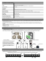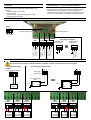
1
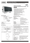
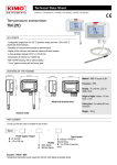
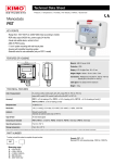
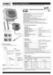
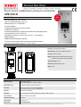
Flush-mount multifunction pressure transmitter
CPE 310-S
KEY POINTS
- Measuring Ranges from -100 to +100 Pa1
- Input for interchangeable probe (Class 310)
- Alternating display of 1 to 3 parameters
- Front face calibration
- Configurable intermediate and centre zero ranges
- 3 audible and visual alarms
- Front face keypad allowing to configure the transmitter and acknowledge the alarm
- 3 analogue outputs 0-5/10 V or 0/4-20 mA
- High resolution in pressure on model -100/+100 Pa (ex : 0.1 Pa) (optional)
- Outputs diagnostic
- MODBUS network RS485 system (optional)
- Front face made of brushed stainless steel with electroluminescent display
1
Other measuring range available on request : from -1000 to +1000 Pa
FEATURES OF THE HOUSING
Front face : Brushed stainless steel 316 L
3.2
92 mm
76 mm
70 mm
44 mm
42.5 mm
Back housing : Flush-mount in stainless steel 304 L
Protection : IP65 in front face
234 mm
218 mm
147.3 mm
196 mm
Display : Electroluminescent alphanumeric (38 x 48 mm)
Protection screen made of inactinic red PMMA
Height of the digits : 14 mm
Back fittings : Barbed fitting Ø 5.2 mm
Weight : 640 g
69 mm
TECHNICAL FEATURES IN PRESSURE
Measuring range
From -100 to +100 Pa
Other available range : from -1000 to +1000 Pa
Measurement units
Pa, mmH2O, mbar, inWG, mmHG, daPa, hPa
Accuracy*
From -100 to +100 Pa : ±0.2% of reading ±0.8 Pa
From -1000 to +1000 Pa : ±0.2% of reading ±2 Pa
Zero drift
None (see “Self-calibration”)
Resolution
1 Pa, 0.1 mmH2O, 0.01 mbar, 0.01 inWG, 0.01 mmHG, 0.1 daPa, 0.01 hPa
Auto-calibration
Manual or automatic (configurable)
Allowed overpressure
25 000 Pa
Response time
1/e (63%) 0.3 s
Type of fluid
Air and neutral gases
*All accuracies indicated in this document were stated in laboratory conditions and can be guaranteed for measurements carried out in the same conditions, or carried out with calibration compensation.
TECHNICAL SPECIFICATIONS
Power supply
24 Vac / Vdc ±10 %
Output
3 x 0/4-20 mA or 3 x 0-5/10 V (4 wires)
Maximum load : 500 Ohms (0/4-20 mA) / Minimum load : 1 K Ohms (0-5/10 V)
Galvanic isolation
On the output
Consumption
5W
Conformity
CEM 2004/108/CE and NF EN 61010-1 directives
Electrical connection
Screw terminal block for cables from 0.05 to 1.5 mm2 or from 30 to 16 AWG
RS485 communication
Digital : Modbus RTU protocol, configurable communication speed from 2400 to 115200 Bauds (optional)
Visual alarm
Blinking of the value
Audible alarm
Buzzer (92 dB at 10 cm)
Environment and type of fluid
Air and neutral gases
Operating / storage temperatures
From -10 to +50 °C / From -10 to +70 °C
SELF-CALIBRATION
Class 300 transmitters have a temperature compensation system from 0 to 50°C and a self-calibration system to guarantee an excellent long-term stability, along
with a great measurement accuracy.
Self-calibration principle : the microprocessor of the transmitter drives a solenoid valve that compensates any long-term drifts of the sensitive element. The
compensation is made by regular adjustment of the zero. The differential pressure measurement is then made regardless of the environmental conditions of the
transmitter.
Solenoid valve lifetime : 100 million cycles
Advantage : no zero drift
Self-calibration frequency : can be disabled or set from 1 to 60 min
INNOVATIONS
➢ Adjustable pressure connections
The CPE310-S transmitter has a two adjustable pressure connections system in front face (A) coupled with two pressure connections at the back (B).
When installing the transmitter, this system allows to configure the differential pressure connections with a set of plugs (supplied with the transmitter).
A
B
Black
Red
-
Front face calibration
This system allows to isolate the back pressure
connections and then to access the sensitive
element (on the front face) of the pressure
transmitter. Without dismantle the transmitter,
this system allows to calibrate by connecting the
transmitter to a pressure generator and a
calibration bench. The calibration is easier and
faster.
+
➢
➢
Front face computer connection
Re d
+
Mini-DIN
connection
Ca libra tion
be nc h
+
USB connection
-
CONFIGURABLE ANALOGUE OUTPUTS
Configurable analogue outputs :
Range with centre zero (-50/0/+50 Pa), with offset zero (-30/0/+70 Pa) or standard range (0/+100 Pa), it is possible to configure your own intermediate ranges.
The minimum configurable range is 10% of the full scale.
-100
0V
4 mA
Configurable ranges according to your needs : outputs are automatically adjusted to the new measuring ranges
0
+100
-100
0
50
10 V
20 mA
New
range
0V
4 mA
10 V
20 mA
+100
ALARMS
INTEGRATION OF PRESSURE MEASUREMENT
The CPE310-S pressure transmitter has 3 visual and audible alarms
that are independent and configurable. Available settings are the
followings :
●
Time-delay duration : from 0 to 600 s
●
Thresholds values
●
Action of the alarm : rising edge, falling edge or monitoring
●
Audible alarm activation (buzzer)
The pressure measurement element is very sensitive and reacts to
pressure changes. When making measurements in unstable air movement
conditions, the pressure measurement may fluctuate. The integration
coefficient (from 0 to 9) makes an average of the measurements ; this helps
to avoid any excessive variations and guarantees a stable measurement.
CONENCTIONS
Modbus :
13 14 15
Pressure connection -
Pressure connection +
B A GND
- +
OUT1
1 2 3
OUT2
4 5 6
Power supply terminal block
For 24 Vac power
For 24 Vdc power
supply models :
supply models :
OUT3
7 8 9
10 11 12
Neutral (N)~
Phase (L)~
or
+
0/4-20 mA – Current
GND – Ground
0-5/10 V – Voltage
0/4-20 mA –Current
GND – Ground
0-5/10 V – Voltage
0/4-20 mA – Current
GND – Ground
0-5/10 V – Voltage
10 11 12
-
ELECTRICAL CONNECTIONS – as per NFC15-100 standard
This connection must be made by a qualified technician. To make the connection, the transmitter must not be energized.
➢
For 24 Vdc power supply
models :
➢
For 24 Vac power supply models :
N L
Power supply terminal block
10 11 12
-
Power supply
terminal block
N L
1 2 3
1 2 3
+
-
24 Vac power supply
class II
~
N
N
230 Vac
24 Vac
L
L
Pe
~
+
24 Vdc power
supply
or
230 Vac
~
24 Vac
~
N
L
N
L
Pe
24 Vac power supply
Connection of the 0/4-20 mA current output :
➢
OUT1
mA GND V
1
+
+
2
3
Regulator
display
or PLC/BMS
passive type
OUT2
mA GND V
4
+
+
5
6
-
Regulator
display
or PLC/BMS
passive type
Connection of the 0-5/10 V voltage output :
➢
OUT3
mA GND V
OUT1
mA GND V
OUT2
mA GND V
7
1
4
+
+
8
9
-
Regulator
display
or PLC/BMS
passive type
2
-
3
+
+
Regulator
display
or PLC/BMS
passive type
5
-
6
+
+
Regulator
display
or PLC/BMS
passive type
OUT3
mA GND V
7
8
-
9
+
+
Regulator
display
or PLC/BMS
passive type
RS 485 MODBUS PROTOCOL
Class 310 transmitters can be linked in one network operating on a RS485 home bus.
The RS 485 digital communication is a 2-wire network, on which the transmitters are connected in parallel. They are connected to a PLC/BMS via the RTU
Modbus communication system. Since the CPE310-S can be configured with the keypad, the MODBUS enables remote configuration, to measure 1 or 2
parameters or to see the status of the alarms...
INPUT FOR CLASS 310 INTERCHANGEABLE PROBES
Adaptor for class 310 probes
Adaptor connection
CONFIGURATION
MOUNTING
70 mm
Ø2.2 mm
196 mm
To install a transmitter on a wall, make a cutting of 196 x 70 mm in the wall. Then drill 4 holes
around the cutting as shown beside. Insert the transmitter into the wall and fix it with the 4 screws
(supplied with the transmitter).
10 mm
Class 310 transmitters allows you to set all the parameters managed by the transmitter : units, measuring ranges, alarms, outputs, channels... via the different
methods shown below :
➢
Via keypad, only on models with display. A code-locking system for keypad guarantees the security of the installation. See configuration manual.
➢
Via software (optional) : simple and user-friendly. See LCC-S user manual.
➢
Via Modbus (optional) : configuration of all parameters from your PC, via the supervision or data acquisition software.
12 mm
Cut-out depth = 43 mm
3 mm
3 mm
CALIBRATION
Adjusting and calibration on site : the professional configuration interface, with a dynamic pressure calibration bench, allows you to adjust and calibrate your
transmitters directly on site or in laboratories.
Outputs diagnostics : with this function, you can check with a multimeter (or on a regulator/display, or on a PLC/BMS) if the transmitter outputs work properly.
The transmitter generates a voltage of 0 V, 5 V and 10 V or a current of 0 mA, 4 mA, 12 mA and 20 mA
Certificate : transmitters are supplied with an individual adjusting certificate and can be supplied with a calibration certificate as an option.
MAINTENANCE
Avoid aggressive solvents. When cleaning rooms or ducts with products containing formol, protect the the transmitter.
OPTIONS
●
●
●
●
LCC-S : configuration software with USB cable
RS5 : RS 485 Protocol Modbus digital output
HRP : high resolution (example in pressure : 0.1 Pa)
Calibration certificate
●
●
●
●
●
Sliding fittings
Connection fitting
Clear tube
Pressure connections
Trough-connections
FTang_transmitter_CPE310-S – 20/12/13 – RCS (24) Périgueux 349 282 095 Non-contractual document – We reserve the right to modify the characteristics of our products without prior notice.
The input for interchangeable probes allows to connect directly on CPE310-S transmitter, via the adaptor cable, an interchangeable probe of the class 310 range
(see technical datasheet of probes for class310 transmitters).
Advantage : the CPE310-S centralises, in addition of the pressure, temperature and humidity measurements of a SHDI150 probe for example.