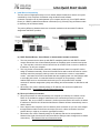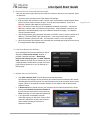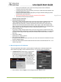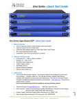
1
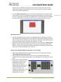
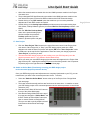
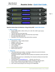
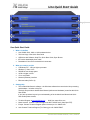
Uno Quick Start Guide Page | 1 Uno Quick Start Guide 1. What’s in the Box Uno U0808, 0816, 1608 or 1616 hardware device This hard copy of the Quick Start Guide USB drive with Software, Help File, Quick Start Guide, Spec Sheets IEC socket detachable power cable Detachable 3.5mm Euro terminal block connectors 2. What you need to provide A Windows PC – 1GHz or higher processor Windows 7, Vista, or XP 500 MB of free storage space 16 Bit or higher colours 1G or more RAM Network (Ethernet) interface Ethernet cable (Cat5 or 6) 3. Getting Help The included NeuConsole software - the Windows software that controls the Uno processing and hardware - includes a Help File. That help file provides a detailed User Manual (software and hardware) as well as this Quick Start Guide. If you have questions beyond your understanding of the included User Manual and Quick Start Guide please contact, Technical Support at [email protected] North America: Contact Technical Support at 905-770-0055 ext 3 (9am-5pm EST). Europe: Contact Technical Support (Marco Koorstra) at +31 29940 1100. Asia: Contact Technical Support (Tim Cheung) at +86 13602279067. Web Site: www.xilica.com XILICA AUDIO DESIGN CANADA / ASIA / EUROPE Uno Quick Start Guide Important Safety Information 1. READ THESE INSTRUCTIONS All the safety and operating instructions should be read before the product is operated. Page | 2 2. KEEP THESE INSTRUCTIONS The safety and operating instructions should be retained for future reference. 3. HEED ALL WARNINGS All warnings on the product and in the operating instructions should be adhered to. 4. FOLLOW ALL INSTRUCTIONS All operating and use of instructions should be followed. 5. DO NOT USE THIS APPARATUS NEAR WATER Do not use the product near water. For example, near a bathtub, washbowl, kitchen sink, or laundry tub, in a wet basement, or near a swimming pool, and the like. 6. CLEAN ONLY WITH DRY CLOTH Unplug the unit from the wall outlet before cleaning 7. DO NOT BLOCK ANY VENTILATION OPENINGS Slots and openings in the cabinet back or bottom are provided for ventilation, to ensure reliable operation of the limit and to protect it from overheating. These openings must not be blocked or covered. The openings should never be blocked by placing the product on a bed, sofa, rug, or similar surface. This product should never be placed near or over a radiator or heat source. This product should not be placed in a built-in installation such as a bookcase or rack unless proper ventilation is provided or the manufacturer’s instructions have been adhered to. 8. DO NOT INSTALL NEAR ANY HEAT SOURCES This Product should be situated away from heat sources such as radiators, stoves, or other products (including amplifiers) that produces heat. 9. DO NOT DEFEAT THE SAFETY PURPOSE OF THE POLARIZED OR GROUNDING-TYPE PLUG A Polarized plug has two blades with one wider than the other. A grounding-type plug has two blades and a third grounding prong. The wide blade or the third prongs are provided for your safety. If the provided plug does not fit into your outlet, consult an electrician for replacement of the obsolete outlet. 10. PROTECT THE POWER CORD FROM BEING WALKED ON OR PINCHED PARTICULARLY AT PLUGS, CONVENIENCE RECEPTACLES, AND THE POINT WHERE THEY EXIT FROM THE APPARATUS. 11. ONLY USE ATTACHMENTS/ACCESSORIES SPECIFIED BY THE MANUFACTURER. 12. USE ONLY WITH CART, STAND, TRIPOD, BRACKET, OR TABLE SPECIFIED BY THE MANUFACTURER, OR SOLD WITH THE APPARATUS. WHEN A CART IS USED, USE CAUTION WHEN MOVING THE CART/APPARATUS TO AVOID INJURY FROM TIP-OVER. Do not place this unit on an unstable cart, stand, tripod, bracket, or table. The unit may fall, causing serious injury to someone, and serious damage to the appliance. A unit and cart combination should be moved with care. Quick stops, excessive force, and uneven surfaces may cause the product and cart combination to overturn. 13. UNPLUG THIS APPARATUS DURING LIGHTNING STORMS OR WHEN UNUSED FOR LONG PERIODS OF TIME. For added protection for this unit during a lightning storm, or when it is left unattended and unused for long periods of time, unplug it from the wall outlet and disconnect the antenna or cable system. This will prevent damage to the unit due to lightning and power line surges. 14. REFER ALL SERVICING TO QUALIFIED SERVICE PERSONNEL. SERVICING IS REQUIRED WHEN THE APPARATUS HAS BEEN DAMAGED IN ANYWAY, SUCH AS WHEN THE POWER SUPPLY CORD OR PLUG IS DAMAGED, LIQUID HAS BEEN SPILLED OR OBJECTS HAVE FALLEN INTO THE APPARATUS, THE APPARATUS HAS BEEN EXPOSED TO RAIN OR MOISTURE, DOES NOT OPERATE NORMALLY, OR HAS BEEN DROPPED. 15. WARNING: TO REDUCE THE RISK OF FIRE OR ELECTRIC SHOCK, DO NOT EXPOSE THIS APPARATUS TO RAIN OR MOISTURE. 16. APPARATUS SHALL NOT BE EXPOSED TO DRIPPING OR SPLASHING AND NO OBJECTS FILLED WITH LIQUIDS, SUCH AS VASES, SHALL BE PLACED ON THE APPARATUS. XILICA AUDIO DESIGN CANADA / ASIA / EUROPE Uno Quick Start Guide 4. Introduction and Description: Thank you Hello from everyone here at Xilica Audio Design and thank you for purchasing our Uno-Series digital processor. Page | 3 Since Uno is setup and controlled by a host computer via Ethernet it is important that we get you connected and up and running as quickly and easily as possible. Thus the first portion of this Quick Start Guide is dedicated to getting the Uno processor and the NeuConsole software connected and operating with ease. If you have any suggestions for making this quick start guide better in that or any regard please bring them to my attention at [email protected] and we will make those changes. Once the Uno processor and the NeuConsole software is connected and operational we believe you will find working with the software and processor to be very straight forward as outlined in the balance of this Quick Start Guide. Uno-Series Digital Processor Designed in Canada and built on the audio performance reputation of our 40 Bit, Floating Point DSP Engine and High Performance 24 Bit Converters - Uno is an apps based DSP that bridges the gap between the ease of use and the lower cost of fixed architecture processors and the flexibility but higher cost associated with open architecture -drag & drop type processors. We call Uno a Hybrid architecture DSP. Simply download a pre-designed DSP app into Uno. There is a pre-designed DSP app for just about every application and with input from users our web site apps library will continue to grow, future-proofing your Uno hardware investment. Uno is available in four I/O model configurations - 8x8, 8x16, 16x8 and 16x16 with Mic/Line input selection per input, 48v phantom power and high performance mic pre-amps. Download pre-designed DSP apps from our web sites Uno Apps Library and load one into Uno’s NeuConsole software and from there into the processor device itself. Each app has DSP modules specific to the pre-designed application and in a specific fixed order. The user then adjusts each DSP module using the supplied NeuConsole software GUI to complete the system processing. From auto-mixing to loudspeaker management Uno has a DSP app that will work for your application. Control Uno via Ethernet using the included NeuConsole software GUI, with the logic input/relay output ports, using the optional NeuPanel - Mini and Touch Series programmable wall controls or any third party controller. Uno provides auto recognition and connection of all Uno devices and controls on the network (in DHCP mode). The Uno Hybrid Architecture – Apps Based Digital Processor from Xilica. No programming skills or DSP design time required – we do it for you. XILICA AUDIO DESIGN CANADA / ASIA / EUROPE Uno Quick Start Guide 5. Hardware: Page | 4 Front Panel 1. Power Status LED A blue Power Status LED will light to notify you that the Uno device is connected to a power source and switched to the ‘On’ position. 2. Network Status LED When the processor has an Ethernet cable / network cable connected the orange Network status LED on the front of the processor will light - once the processor initializes. If there is no Ethernet / network cable attached it remains off. Note: When the Network status LED is on it does not mean that you have established a Network Connection – only that an Ethernet or network cable is connected to the processor. Proper Network Connection and Operation is indicated/displayed only in the software’s “Network View” page (see the Network View & Connection section of this guide). When the processor and software are connected and communicating the orange Network status light will flash. 3. Input/Output Signal Indicators Each Input and Output channel has a dual colour LED signal indicator. Green for signal present at -40 dBu and Red at +17 dBu at the advent of analog clipping. Rear Panel 1. 2. Power On/Off Switch Fuse Compartment Should you need to replace the fuse use a T-Series 2.5A-250v fuse. Ensure power to the device is disconnected when replacing the fuse. 3. Power Input Connector Insert the IEC plug connector end of the supplied cable into the rear panel of the Uno. Connect the AC end of the cord into an AC power source of the correct voltage and frequency (100-240 VAC, 50/60 Hz). 4. Ethernet Connector Uno utilizes a TCP protocol for communication with the host PC running the NeuConsole software. The port is a standard RJ45 (Ethernet) jack. 5. 6. IP Reset Button. See the IP Reset / Reset Processor Network Settings section in this guide. Logic Control Input/Output Port Utilizing twisted pair wire with an attached terminal block, you can use external signals to control parameters such as triggering presets within NeuConsole. 7. Analog Line Outputs Euro/Phoenix style terminal block output connections utilizing 3.5mm terminal block connectors (included). Use balanced, shielded audio cabling. Uno has eight (8) or sixteen (16) outputs depending on the model. 8. Analog Mic/Line Inputs Euro/Phoenix style terminal block input connections utilizing 3.5mm terminal block connectors (included). Use balanced, shielded audio cabling. Uno has eight (8) or sixteen (16) switchable Mic/Line inputs w 48v phantom power depending on the model. XILICA AUDIO DESIGN CANADA / ASIA / EUROPE Uno Quick Start Guide 6. Install the NeuConsole Software: The USB drive included with each processor includes a copy of the Uno’s NeuConsole software or you can download the Windows 7, Vista, XP compatible NeuConsole software from our web site and install on your computer (www.xilica.com). Page | 5 Note: The Microsoft installation program/process remembers what location you installed from - the first time you load the NeuConsole software into your computer. This can cause issues if you try and load a new software Version (update) from a different location than the location originally used to load the NeuConsole software into your computer (USB, Internet Download, etc). Solution: Simply un-install the old NeuConsole software version in Control Panel before you update your software version each time. You won’t have any update issues and you won’t have to remember what location you loaded the software from previously or what the source-USB, Internet, etc. Make sure that the software version you are installing is the latest version available – as indicated on the web site. If you have a personal Firewall setup on your computer, a Firewall popup window might be displayed during the software installation to ask whether users want to “Block” or “Allow” NeuConsole from accessing the network. Select “Allow” to continue installation. Once installed and working – close the NeuConsole software for now until you are instructed to open it again. 7. Download and Save Some Pre-Designed DSP Apps/Schematics: Before you begin working with the NeuConsole software and your processor - go to our web site at www.xilica.com and from our Uno Apps Library select and save to a folder in your computer some or all of the pre-designed “Uno DSP Apps/Schematics”. These are the pre-designed DSP apps/schematics for a variety of applications that you will select from to use in your DSP design project in conjunction with the NeuConsole software and the Uno processor. Note: You are able to work with the NeuConsole Software and any pre-designed DSP app/ schematic “Offline” without being connected to a network or processor. Make DSP parameter adjustments, etc and save that work as you go. Later you can connect to the processor and transfer/save your DSP design project work file into the processor device. XILICA AUDIO DESIGN CANADA / ASIA / EUROPE Uno Quick Start Guide 8. Initial Device Connectivity The Uno series of digital processors run on a network based infrastructure and are set up and controlled by a host computer via Ethernet using the NeuConsole software. A network connection can be made between your computer and Uno (a) Via a DHCP enabled Router (or a DHCP enabled Server/Router combination) or (b) Directly using an Ethernet cable (or indirectly via an Ethernet switch). The primary difference between these two connection methods is the automatic IP address assignment that DHCP provides. (a) DHCP Enabled Router, Server/Router or Router/Switch Combo Connection The Uno processor device boots up with DHCP enabled by default so with DHCP enabled routers and servers Uno will automatically obtain an IP address upon connection and power up. This may take a minute or two as Uno will look for a DHCP router or server to obtain its IP address - as will your computer. This is by far the recommended connection method whenever there is no specific need to assign IP addresses manually. Since the Xilica Mini Series wall controls will often be used to remotely control the processor and they need to be connected to a router or router/switch combo - and better still a POE router/switch that also supplies power over the Ethernet cable to each Mini wall control - the standard network connection of the processor, a DHCP enabled POE router or router/switch combo and your PC will provide DHCP enabled automatic IP address assignment quickly and reliably (and accommodate our Mini Series wall controls). Where there is a need to manually assign an IP address, this can be accomplished in Network View. See Network View and Connection below. (b) Direct (or Indirect) Connection When the processor is connected directly to a computer (or indirectly via a switch or hub) DHCP is not available to assign IP addresses so the connection process is not quite as automatic. But, once no DHCP is detected - the Uno processor device will revert to is default IP address of 169.254.128.128 and the NeuConsole software will then automatically connect with the device. Note: Most modern computers can now detect a direct connection so you can use a straight through Ethernet cable for the direct connection (if there is a direct connection issue that persists then you might try a crossover type Ethernet cable). Where there is a need to manually assign an IP address, that can be accomplished in Network View (right click the device and select Device Setup to make changes to the network connections). See Network View and Connection below. XILICA AUDIO DESIGN CANADA / ASIA / EUROPE Page | 6 Uno Quick Start Guide 9. Processor Device Connected and Powered Up: With your processor/s (and devices) connected as a network or directly to your computer, power on all devices. On power up the processors blue Power Status LED will light. If the processor has an Ethernet cable / network cable connected the orange Network Status LED on the front of the processor will light - once the processor initializes. If there is no Page | 7 Ethernet / network cable attached it will remain off. Note: This does not mean that you have established a Network Connection – only that an Ethernet or network cable is connected to the processor. Proper Network Connection and Operation is indicated/displayed only in the software’s Network View page – see Network View & Connection below. Upon being powered up the processor will search for a DHCP router or server to obtain an IP address. If it locates DHCP it will connect quickly. If not, the processor will revert to its default IP address (169.254.128.128). This may take a minute or so to accomplish. When the processor and software are connected and commands are being sent to the device the orange Network status light will flash. 10. Launch the NeuConsole Software: Upon opening the NeuConsole software you will be shown the “NeuConsole StartUp” window. It provides 3 possible selections – New Design Project, Open Design Project, and Start “Network View” (Network View will also be available to you as a separate button located at the top right of the main Project Design window once you are working on a DSP project). 11. Network View and Connection: Click Start “Network View” from the NeuConsole Start Up window. The Network View displays all Uno processors and control devices connected to the network (including Mini-Series wall controls, etc) and information such as the processor device model, a green, yellow or red network connection indicator, the IP address, and the NeuConsole software version. In Network View you should now see your processor device model connected to the router block and the Network Connection Indicator to the left of the processor device model should be Green (meaning it is connected and operational). If your processor and software have Not connected properly you will see a Yellow or Red connection indicator to the left of the processor device model indicating a connection or operational problem. XILICA AUDIO DESIGN CANADA / ASIA / EUROPE Uno Quick Start Guide Network Connection Indicators Green - Connected and operational. Yellow - Connected/online but Not operational. Red - The processor is offline – not connected – no communication between the NeuConsole software and the processor. This could be a temporary Offline interruption if the processor is busy performing a firmware upgrade or the processor is rebooting. Plus check device cables, connections and power. 12. Connection Problems? Yellow Network Connection Indicator While in Network View if there is a Yellow network connection indicator next to the processor device model the device is connected/online - but Not Ready / Not Operational. There are a number of network problems that can create the Network Connection Indicator to be Yellow so to assist in identifying the problem, when the indicator is Yellow you can hover your cursor over the device and there is a pop-up Tooltip message to tell you the kind of issues it has detected. Some probable causes include, When you are not connected to a DHCP enabled router or server the processor will detect this and revert to its Default IP Address (169.254.128.128). If you see that default IP address shown in Network View you know its default IP address is in effect. Close down the NeuConsole software and open it again. This will usually resolve the issue and the network connection indicator to the left of the processor device model in Network View should now be Green – indicating that the processor and software are now connected and operational. If after the software re-boot above the connection indicator is still Yellow (connected but Not Ready/Operational), it is possible that the processor has retained a previously assigned IP address and is holding onto it and not allowing the processor to revert to its default IP address. To resolve this potential issue the processors network settings and password need to be reset. See IP Reset Push Button below. IP Reset Push Button / Reset Processor Network Settings and Password o Close down the NeuConsole software and Power down the processor device. o At the rear of the processor you will see a small round recessed push button labeled “IP Reset”- just to the right of the Ethernet connector (looking from the back). You are able to push this reset push button inward using the point of a pen or a small pointed object. o Press the IP Reset push button inward and while holding it pushed in power up the processor device. o Wait 5 seconds after power up and then release the IP Reset push button. o Wait for the processor to power up completely (this will take a minute or so as it initializes and sets its default IP address). o Open the NeuConsole software and select “Start Network View” again. In Network View (once the processor and software communicate with each other) you should now see the Green network connection indicator to the left of the processor device model indicating that all is now connected and operational (and you will notice the default IP address of 169.254.128.128 is shown). Note: Some Uno processors were manufactured with a different IP Reset switch that was hidden behind a removable cover on the rear of the processor. If yours is like that – follow the instructions below to reset the processors IP network settings and password. XILICA AUDIO DESIGN CANADA / ASIA / EUROPE Page | 8 Uno Quick Start Guide o o o o o Remove the small black cover on the rear of the processor near the Ethernet connector (remove 2 small screws). Looking from the back of the processor you will see a small black Reset Switch to the right of the Ethernet connector. Press this Reset Switch forward lightly with your finger and while holding it pressed forward power up the processor. Wait 5 seconds after power up and then release the Reset Switch. Page | 9 The balance of the process is as above. Probable Causes Continued…… Device Schematic Not ready. If the Popup Tooltip message shown when you hover over the device in Network View says “Device Schematic Not ready” then the processor has already been loaded with a predesigned DSP app schematic. Give the connection process a minute to connect and if it does not connect close the NeuConsole software, open it again, select Start Network View and you should now see that the processor is connected and operational - as indicated by the Green network connection indicator to the left of the processor device model. DSP Processing Error. If the Popup Tooltip message shown when you hover over the device in Network View says “DSP Processing Error” this could be a bad pre-designed DSP app schematic. You may need to reload the pre-designed DSP app schematic and restart and/or restart device to reset its DSP chip. Device NOT READY. Restart device. Reboot software. Error in Firmware Upgrade. It will print out an error code when you hover your cursor over the device in Network View (Do Firmware Upgrade again). Device can communicate to NeuConsole with UDP but cannot communicate with TCP. It’s a network setup issue 13. Manual Assignment of IP Addresses: There are applications that require or prefer that the IP addresses be manually assigned (the same solution may apply to some connection issues). To manually assign IP addresses, In Network View as shown below - right click the processor device and select “Device Setup”. In the Network Properties window as shown at the right - select “Change Network Configuration” in order to disable DHCP and to insert IP addresses manually (it also provides two built in test procedures, device security, and device information). When finished – Select “Apply” to save changes and then “Done” to exit. XILICA AUDIO DESIGN CANADA / ASIA / EUROPE Uno Quick Start Guide 14. Locating your Computers IP Address Information: In this section, we will be navigating through Microsoft Windows to determine your home networking information as it applies to manually assigning IP Addresses. The first step is to open the 'Start Menu' and select 'Run...' In the newly opened 'Run' window, type 'cmd' into the 'Open' box. Hit enter or click 'OK'. You have now opened the command prompt, where we can display the TCP/IP Network Configuration information. Type 'ipconfig/all' (No Quotes) and hit enter. From this list of values, you can now locate your network's 'Default Gateway', 'IP (IPv4) Address' and 'Subnet Mask' values. To determine an IP Address for your Uno, utilize the first 3 values (Octets) of the 'IPv4 Address' and select the desired value for the fourth Octet. Ensure that the value you choose is unique to any other system on your network. Reference the IP address (IPV4) of your PC in the TCP/IP Network Configuration menu for an example of how the IP address should be structured. XILICA AUDIO DESIGN CANADA / ASIA / EUROPE Page | 10 Uno Quick Start Guide 15. Firmware Upgrade to Processor Device: Once you have the processor device and the NeuConsole software connected and operational and before you start work on a DSP design project it is wise to make sure your processor has the latest firmware installed (firmware as opposed to software). To do a Firmware Upgrade, In Network View – Right click the device; Select “Firmware Upgrade” from the menu and follow the instructions. Note: As indicated during the firmware upgrade procedure – a firmware upgrade will erase all saved data on the device. Thus perform this procedure before you load a completed DSP Design Project into the processor device. 16. Project View (in Design Mode): Once you have completed setting up your network connection you can begin to work on a New Design Project. In the following example the processor is connected / operational. New Design Project If you are still in the Network View window – Go to “File” at the top left and select “New Project” in order to begin a new DSP design project. If you have just opened the software - from the NeuConsole Startup window you can select “New Design Project” in order to begin a new DSP design project. Either will open the “Project View” work area page (in Design Mode - as identified by the dotted alignment work area). See the Project View and Design Mode headings at the top left of the work area. Note: Once you are in Project View working on a DSP design you are able to switch between “Project View” and “Network View” by selecting the Network View button at the top right of the work page area. Once you do it XILICA AUDIO DESIGN CANADA / ASIA / EUROPE Page | 11 Uno Quick Start Guide will take you to the Network View page and the button will re-name itself “Project View”. Selecting the Project View button will take you back to the Project View page to continue working on your DSP design project. From the System Components menu on the left, click and drag the Uno processor model you are going to use for your application and this DSP design project onto the white work area. For our example we chose the Uno U0808 model (you will notice that the Uno U0808 processor model placed in the project view work area is a light see through red colour). Map Physical Device With the Uno U0808 processor model for this application placed in the Project View work area (and when the processor device is connected to the NeuConsole software) we need to map or connect the Uno software processor model in the work area with the actual physical Uno processor device that is connected to the software. To do this, Right click the Uno processor module in the Project View work area; Select “Map Physical Device” and then select the processor device model you are working with from the drop down list. Once done you will notice that the processor device in the project view work area has turned from light see through red to a solid red. Importing a Pre-Designed DSP App Schematic into your Design Right click the U0808 processor module in the Project View work area again and select “Import DSP App Schematic from File”. That will take you to the folder where you saved your pre-designed Uno DSP Apps/ Schematics early on in this quick start guide or you can browse to the file where you saved them. Select the pre-designed DSP App /Schematic you want to use for this application and then click “Open” (make sure the predesigned DSP app schematic you choose matches the processor model you are using – for example, you cannot load a U1616 pre-designed DSP app into a U0808 processor device). XILICA AUDIO DESIGN CANADA / ASIA / EUROPE Page | 12 Uno Quick Start Guide Wait a few seconds and then double click the Uno U0808 processor module in the Project View work area. The pre-designed DSP App/Schematic now resides in the U0808 processor module in the work area and it opens to show all its DSP modules and the DSP schematic design. Double clicking on any DSP module opens that module so you can make parameter adjustments to each DSP module as required. Double clicking on the Analog Input module provides access to the master analog input Gain, Mutes, Polarity & Meters (plus the processors Mic/Line Pre-Amp Setup controls – see below). Click the “Mic/Line Pre-Amp Setup” button in the opened Analog Input window to adjust the processors Pre-Amp parameters (mic/line selection, phantom power and gain). 17. Save Project Click the “Save Project” Disc located to the right of the zoom control in the Project View work area to “Save Project As” or “Save” your DSP design project (each time a DSP adjustment is made the Save Project Disc will appear) OR Select “Save Project As” under the File menu at the top left of the application to name and save your design project and “Save Project” to save as you work. This saves the DSP design project you are working on to your PC/Computer (not to the physical processor device – see Switch to Online Mode below). When you name your saved DSP design project that name also appears in the Project View page at the top left - replacing the heading Project as well as being saved in the Component Properties page on the right hand side of the Project View page. 18. Switch to Online Mode (Transferring or saving your DSP design project to the connected physical processor device) Once your DSP design project and adjustments are completed (and saved to your PC) you can transfer/save your work to the connected processor device. To do this, Select the “Switch to Online Mode” button at the top of the Project View / Design Mode work area page. This button selection actually performs two functions at the same time – it transfers or saves your DSP design project to the connected processor device and that processor is now Online and active (live). Note the master “Mute All Devices” button at the top of the Online Mode page. Note that the Design Mode label at the top of the page has changed to “Online Mode” and that the “Switch to Online Mode” button has been re-named “Switch to Design Mode”. Thus you are able to quickly switch back and forth between Online Mode and Design Mode. XILICA AUDIO DESIGN CANADA / ASIA / EUROPE Page | 13 Uno Quick Start Guide Note that the bar at the top of the Online Mode work area page is now Red (not blue). Note that the dotted design mode work area is now a plain white background. Note that when you collapse the design schematic back to the processor module view the processor device model has a green indicator beside it to indicate that the processor device is connected, in Online Mode and active. You can continue to make adjustments to the DSP modules in Online Mode. When you do, upon switching back to Design Mode you will be asked “do you want to copy the Online device parameter settings (or changes) back to your design project – yes or no”. So you can make all kinds of parameter adjustment changes to the DSP modules in Online Mode, hear their effect live, and not affect the related DSP design project file as saved on your PC if you select “No” from that menu. Or select Yes and all those changes will be saved in the DSP design project file on your PC (and the processor). 19. Working Offline. Of course you can import a DSP app, work on a DSP design project and save it to a file while “Offline” - with no processor device connected, no Map Physical Device action taken and without transferring / saving your work to the processor device right away. Then later, connect processor, open your saved project, Map Physical Device, and transfer/save your saved DSP design project file to the connected processor device by selecting the “Switch to Online Mode” button. 20. Open Design Project Open Design Project or Open Project is where we open or access previously worked on and saved DSP design project files. From the software NeuConsole Startup window – Select “Open Design Project” and select and open the specific DSP design project saved in your files. Or - From the Network View or Project View window - Go to “File” at the top of the page, select “Open Project” and select and open the specific DSP design project saved in your files. In both cases the saved DSP design project once opened will appear in your Project View/ Design Mode work area. Double click the processor module in the work area to view the saved DSP design project schematic. Double click DSP modules to open them and make parameter adjustments as required. Save your work as you go and the balance of your work operations are the same as described above in New Design Project. 21. Component Properties Menu Note: The Component Properties menu on the right side of the Project View work area normally provides the means to alter the specific characteristics of each individual DSP Module and to make other changes when the NeuConsole software is used in conjunction with a Xilica DSP model other than Uno. In Uno only a few of the basic window naming functions can be modified. XILICA AUDIO DESIGN CANADA / ASIA / EUROPE Page | 14 Uno Quick Start Guide 22. Open Device (Quick Access to a Programmed Processor Device) If you are connecting to a processor device that already has a Pre-Designed DSP App/ Schematic loaded into it and you need quick access to the processors DSP to check out its settings or to make new DSP module parameter adjustments, Connect to the processor device. Open the NeuConsole software. From the NeuConsole Startup window select Start “Network View”. In the Network View window make sure the network connection indicator to the left of the processor device model is Green (connected and operational). At the bottom of the Network View page see “Open Device”. Select “Open Device” to open the DSP design project /DSP app schematic saved on the connected processor device. The processors DSP is active (live) now just as it is in Online Mode. Double click DSP modules to open and make parameter adjustments to the DSP modules in real time. Note: Any parameter changes you make from “Open Device” mode will be maintained in the processor device but will not be saved to the specific DSP design project file as saved on your PC. Thus no one can accidently alter the original saved DSP project design file while working in the Open Device operating mode. You must be working with the processor device in Design Mode or Online Mode in order for such changes to be saved to the DSP Design Project File on your PC and you have control over what is saved and what is not and if the processor device should have its settings updated or not via the pop up windows presented as you work. 23. Additional Operational Guidance That should get you connected, operational, downloading pre-designed DSP app schematics into the software and processor, creating new design projects, opening and working on saved DSP design project files, transferring/saving your DSP design projects to the processor, and working in Online mode and Open Device mode. For more detailed operational guidance (regarding Presets and other topics) please see the detailed User Manual that can be viewed in the NeuConsole software” Help File” or the Help File as saved on the USB drive packaged with each processor (this Quick Start Guide can be found in both locations as well). XILICA AUDIO DESIGN CANADA / ASIA / EUROPE Page | 15 Uno Quick Start Guide 24. Uno DSP Remote Control The Uno processor can be remotely controlled using its NeuConsole software GUI, with the logic input/relay output ports, using the optional NeuPanel - Mini and Touch Series programmable wall controls, or any third party controller. See www.xilica.com for spec sheets and information. Page | 16 25. Warranty/Service/Return Authorization The UNO Series is warranted covering materials and workmanship for a period of Two (2) years, as determined by the date of retail purchase (according to the sales receipt from an authorized dealer) or the date of manufacture if the sales receipt is not available (according to the serial number). This warranty applies to the product; therefore, the remainder of the warranty period will be automatically transferred to any subsequent owner. This warranty applies only to failure of a Xilica product caused by defects in materials and workmanship during the stated warranty period. It does not apply to a unit that has been subjected to abuse, accident, modification, improper handling/installation, or repairs made without factory authorization or by anyone other than authorized Xilica Field Service Stations. This warranty is void if the serial number has been defaced, altered or removed. Products covered by this warranty will be repaired or replaced at the option of Xilica, without charge for materials or labor, provided all the terms of this warranty have been met. Owner is responsible for return ship costs to Xilica. Return shipping to owner paid by Xilica. For factory service, please call or email for a Return Materials Authorization (RMA) number before shipping. When the product is shipped, the following information must be included in the RMA form and on the package: 1. Owner’s complete name, daytime phone number, email address and return street address. 2. The serial number of the product being returned 3. A complete description of the problem(s) experienced, including a brief description of how the equipment is being used and other equipment involved. 4. A completed RMA form inside the carton with the product. 5. A copy of the retail sales receipt inside the carton with the product, if possible. 6. The RMA Number written on the Outside of the shipping carton. Again, from everyone here at Xilica Audio Design, thank you for your support of our Digital Processors. Kind regards, Barry Steinburg [email protected] XILICA AUDIO DESIGN CANADA / ASIA / EUROPE