1
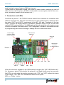
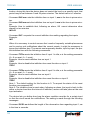
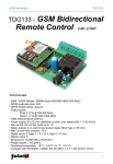
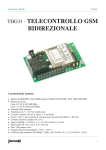
USER MANUAL
TDG140
TDG140 - GSM Remote Control
with DTMF
Technical data
• GSM / GPRS Module: SIM900 Quad (850/900/1800/1900 MHz)
• GPRS multi-slot class 10/8
• GPRS mobile station class B
• Output power:
Class 4 (2 W @ 850-900 MHz)
Class 1 (1 W @ 1800-1900 MHz)
• GSM external stylus antenna
• Power supply: 9 to 32 Vdc stabilized (or with Li-Ion battery 800 ÷ 1,000 mA/h)
• Idle current: 50 mA idle, peak up to 1 A
• Relay outputs: 2, to control low tension loads, SELV type (< 60 Vdc)
• Max current relay contacts: 10 A
• Digital inputs: 2 (logic 1 = 5 ÷ 32 V; logic 0 = 0 V)
• Dimensions: 103x67x28 (LxWxH) mm
• Operating temperature: -10°C ÷ +55°C (14 °F - 131 °F)
• Weight approx.: 100 grams
• Complies with EN 60950-1 (2006), EN 301489-7 V.1.3.1, EN 301511 V9.0.2
1
TDG140
USER MANUAL
TABLE OF CONTENTS
1. Important information ............................................................................................. 3
2. Safety instructions................................................................................................... 3
3. General information................................................................................................. 4
4. Operating conditions............................................................................................... 4
5. Proper use............................................................................................................... 5
6. Description.............................................................................................................. 5
7. Connectors and LEDs............................................................................................. 6
8. Installing the USB.................................................................................................... 7
9. Start-up.................................................................................................................... 7
10 Configuration........................................................................................................... 7
11. Configuration SMS................................................................................................... 8
12. Table of command and configuration SMS............................................................ 17
13. DTMF Commands................................................................................................. 18
14. Managing the device through a computer ............................................................ 21
15. Troubleshooting..................................................................................................... 27
2
USER MANUAL
TDG140
1. Important information
Please, carefully read the information in this manual before attempting to operate the
device in order to protect yourself and use the equipment properly. This device shall be
exclusively utilized for its intended use. In no event shall the company Futura Elettronica, or its dealers, be held responsible for any damage, either extraordinary, incidental
or indirect of any nature (financial, physical, etc.), arising from the possession, use or
failure of this product. In case of changes to the device, tampering, or non-compliance
with the instructions in this manual the warranty will be null and void.
The device contains highly integrated components that can be damaged by
electrostatic discharge. Therefore, do not touch any metal part (tracks, component terminals, etc.) with your hands.
Only handle the device by the edges in order to avoid touching the components on the board.
Notice
The user who makes the module operational by adding further components or by putting it into a housing is seen as a manufacturer and is obliged to hand out all the necessary technical documentation as well as place his name and address on the device.
Products made with this equipment have to be considered as industrial products from
the safety perspective.
The phone costs related to sending SMS generated by the device are charged on the
SIM in the device.
2. Safety instructions
In accordance with the current regulations on safety, whenever using a device
under tension all necessary precautions shall be taken. The device must always
be installed in absence of tension.
•The device must be placed into a suitable housing before use. During the installation,
the device must not be connected to the power source or to other devices.
• Before handling the device or opening the container where it has been placed, unplug
the power connector and make sure the circuit is not live.
•Before working with any kind of tool on the device make sure it is disconnected from
the power supply and that components that store energy (capacitors) are discharged.
•All cables connected to the device, particularly the power supply ones, have to be
checked regularly for fractures or damage of the isolation shield. If cables are visibly
damaged, the device has to be switched off immediately until they have been replaced.
• Strictly comply with the technical specifications of components or modules used with
this device. If the information contained herein and/or the information on the components or modules used with the device are not clear enough, please contact a
qualified technician.
3
TDG140
USER MANUAL
• Before starting the device, carefully check whether it is suitable for the intended field
of application. In case of doubt, please contact a qualified technician or the Manufacturer / Dealer.
• The Manufacturer / Dealer cannot be held responsible for improper handling or wrong
connections, therefore it cannot be held responsible for any damage that may result.
• Devices that operate with <35 Volts must be connected by a qualified technician.
• Before starting the device check there is no current leakage in the housing.
3. General information
For EU residents
Environmental information related to this product
This symbol on the device or package indicates it is forbidden to dispose of the
product in the environment at the end of its lifecycle as it could be harmful for
the environment itself. Do not dispose of the product (or batteries, if used) as
unsorted waste.
For more information about the recycling of this product, please contact the city
hall, your local waste disposal service, or the shop where it was purchased.
4. Operating conditions
Warning: before making connections to the device, carefully verify that the supply tension and the tension applied to the relay contacts correspond to those described in this
manual!
Important information:
• The device must be installed in compliance with the current safety standards.
• Supply the remote TDG140 only with stabilized DC tension between 9 and 32 V,
to be applied to the power plug (see Picture 1) keeping in mind the polarity (center
positive). Use a safety current-limited power supply providing current of at least 1 A.
The power cable must not exceed 3 meters.
• The relay outputs in the device can only be used to control low tension loads SELV
type (<60 Vdc).
•The tension applied to the contacts of each relay must not exceed 60 V.
• The switching current on the relays must not exceed 10 A*.
•The maximum tension applied to the digital inputs is 32 Vdc.
• The device can work in any position.
4
USER MANUAL
TDG140
• Check that the section of the cables used is enough.
• The operating temperature of the device ranges between -10 °C and +55 °C (14 °F
– 131 °F).
• If moisture condensation occurs, wait for at least 2 hours before starting the equipment.
• Keep the device away from flower vases, sinks, water pipes, etc.
• The container used to house the device must have adequate ventilation holes.
• Protect the device from moisture, spray water and heat.
• The device is meant for operation in clean and dry rooms.
• Do not expose the device to heavy vibrations.
• Do not use the device in presence of flammable gases, vapors or dust.
• The device can only be repaired by a qualified technician.
• When repairing the unit, original parts must be used. The use of differing spare parts
can cause serious material loss or personal injury.
*the tracks connecting the relay contacts to the terminal are sized considering a load
activation which absorbs 10 A. for short periods of time.
5. Proper use
This device is designed for the remote switching of electric and electronic units via the
GSM network and for the remote retrieval of status information of its inputs by means
of SMS messages automatically generated after those inputs change status. A different
use is not allowed.
6. Description
The TDG140 is a bidirectional remote control module easy to install and simple to use.
With the TDG140 it is possible to remotely control two relays (in monostable or bistable
mode) by means of special SMS commands (with a password) or by means of DTMF
tones sent from any mobile phone. it is possible to store up to 8 telephone numbers to
which the device sends SMS and phone calls when (according to the settings made
during the configuration) it considers the inputs active.
Apart from the TDG140, you will need a valid SIM Card from any network provider
(GSM 900 / 1800 MHz). When using a prepaid SIM Card always check the available
5
TDG140
USER MANUAL
credit so that in case of alarm a SMS can be sent.
Typical fields of application regard the control of power loads, switching on and off
alarm devices, the reception, via SMS, of information concerning the state of door sensors, movement sensors, level sensors, etc.)
7. Connectors and LEDs
As shown in picture 1. the TDG140 remote control has a terminal for connection with
different external units. Pairs IN1 and IN2 are two opto-isolated inputs, while the other
two pairs (OUT1 and OUT2) correspond to the NC, NO and C contacts of the two
relays. Connect the supply tension of the device, between 9 and 32 Vdc, to the outlet
marked PWR (center positive). Via USB (optional) directly installed on the card you can
connect a computer, with the special “TDG Configurator” software it is possible to make
all programming and function setting or change the list of authorized users.
Power supply
connector PWR
(center positive)
USB interface
(optional)
SIM card
slot
SMA female
connector
for GSM antenna
Picture 1
LD1
C NO NC NC NO C
OUT 1
OUT 2
+
-
IN 1
+
LD2
LD3
LD4
LD5
-
IN 2
When the device is engaged in the GSM network research the “LD5” LED flashes at 1
Hz frequency; when it is hooked in the network, it will flash briefly every two seconds;
the LED is on only when the module receives a call. “LD1” and “LD2” indicate the status
of the relays; “LD3” and “LD4” indicate the status of the inputs.
LD1 on = Relay 1 active
6
USER MANUAL
TDG140
LD2 on = Relay 2 active
LD3 on = IN1 active (logical condition set reached)
LD4 on = IN2 active (logical condition set reached)
LD3 and LD4 also report SMS reception (both of them flash for a few seconds), CALL
reception (both LEDs on) and CONFIGURATION CALL on hold (both LEDs turn on
alternatively after start-up and without phone numbers stored in the list).
8. Installing the USB
A special USB interface (code FT782M), available separately, must be installed on the remote control card as shown in the picture
alongside, the mini USB connector must be
upwards.
9. Start-up
You must first obtain a valid SIM Card from a GSM network provider. Use a common
mobile phone to disable the SIM Card PIN. To do so, check the manual of the mobile.
If the SIM Card PIN is not disabled, the device cannot work as it cannot connect
to the GSM network.
Before feeding the TDG140, please insert the SIM Card into the SIM Card holder (mind
the orientation), making sure it is correctly blocked, the connect cable of the antenna to
the connector. Now connect the power supply.
10. Configuration
The device can be set as follows:
- EASY SETUP (Configuration through call)
- PROFESSIONAL SETUP (Configuration through SMS)
- COMPUTER SETUP (Configuration through PC connection: it needs a USB interface,
code FT782M, available separately)
1) EASY SETUP (Configuration through call made on start-up)
When the device is supplied with power, “LD5” will immediately flash at 1 Hz frequency.
The TDG140 will try to connect to the GSM network; when connected, “LD5” will briefly
flash every two seconds or so. After the system initialization (which may take several
seconds). the device alternately illuminates the yellow LEDs “LD3” and “LD4” to indicate the “configuration call” on hold, which should take place within 3 minutes. If during
this time the unit receives a call, it stores the caller’s number (to which reply SMS will
be sent) in the first memory location, it turns the two LEDs off and becomes operative;
otherwise, at the end of the interval, it switches off the yellow LEDs and waits for the
configuration SMS (“PROFESSIONAL SETUP” mode).
7
TDG140
USER MANUAL
2) PROFESSIONAL SETUP (Configuration through SMS executable at any time)
This mode takes full advantage of the device with operations as both outputs switch,
inclusion of additional phone numbers to manage the device, reception of alarm messages, change of SMS text generated by the TDG140, change output activation timing,
and, in general, set the TDG140 with all parameters via simple SMS.
A full reset to restore the defaults settings can also be made via SMS. The syntax for all
available commands can be found in Section 11 (Configuration SMS).
3) COMPUTER SETUP (Configuration through PC connection:
This mode easily allows you to set up the TDG140 – with no additional cost – through a
computer (with a special software) connected via USB code FT782M (optional). Chapter 14 provides all necessary information to make the best use of this configuration
mode.
Configuration through call
Turn on the device, wait till the yellow LEDs “LD3 e LD4” start to flash alternately; then,
with the mobile used to control the TDG140 call the phone number corresponding to
the SIM Card in the remote control. The device will reject the call and store the caller
number in the first memory location. “LD3” and “LD4” will flash rapidly to indicate the
operation.
Check that the mobile used for the configuration has an active ID, i.e. the “hidden call”
or “private call” has not been enabled. To return to the standard c configuration with
active ID, please refer to the mobile instruction’s manual. To check your own mobile
configuration simply call another mobile: The caller ID is active if it displays the number
or name of the calling mobile.
NOTE: Yellow LEDs “LD3” and “LD4” lighten up alternately until the TDG133 is
set up with a call within the first three minutes of start-up. If time is up and no
configuration has been made, the TDG133 turns off the two LEDs and waits for
the configuration SMS. The EASY SETUP mode can be restored by disconnecting
and reconnecting the power supply: you will have three minutes to set up the
device.
11. Configuration SMS
Commands and settings can be sent from any mobile via SMS as long as the message
includes the password (essential to ensure the setting cannot be made by outsiders).
To speed up certain commands, it is possible for the device to store 8 numbers enabled
to send commands without the password.
The numbers in the list are the same to which (if enabled) a few rings or alarm messages will be sent.
However, there is a series of “sensitive” functions, that no matter who sends the SMS,
require a password: in particular, functions that add or remove other numbers from the
list, that change the current password, or request the list of approved numbers.
As a result of a command or query, the device replies with an execution confirmation
SMS or a SMS with information about the settings.
8
USER MANUAL
TDG140
Please note that all commands that do not require a password are effective only
if they come from a recognized phone, that is a phone which number is in the list
of those stored in the remote; an outsider needs a password.
The remote accepts multiple SMS, that is SMS with more than one command, in order
to save money; commands must be separated by a comma. Of course, a multiple command will produce several answer messages, in order to disable this you can disable
the reply by adding at the beginning of the multi command SMS the string RISP, (see
the description of this command).
The device can also be managed by means of DTMF commands send only during a
telephone conversation with the module.
Those commands can be send from any phone (if the DTMF management filter has
been disabled) or only from a number in the list (if, instead, the filter is active). The user
can decide whether the management of the device through DTMF tones needs the
protection of a password, no matter if the calling number is already in the list.
Here are four categories four commands that manage the outputs, the inputs, the communication and the setting of the device. Here we present and describe all commands
that can be sent to de device via SMS.
Note: Every command must be CAPITALIZED and written without spaces.
-Command PWDxxxxx;pwd changes the password; xxxxx is the new password (numeric, five digits) and pwd is the current password (the default password is 12345).
Example: 54321 as the new password and 12345 as the current password
PWD54321;12345
Note: the password is required.
-Command NUMx+39nnnnnnnnnnn;pwd stores a phone number (up to 8 numbers,
19 digits each) in the device; x is its position in the list; nnnnnnnnnn is the phone
number with country code (+39 for Italy); pwd is the current password.
Example: how to enter number 3498911512 in the 8th position
NUM8+393498911512;12345
Note: the password is required only if you try to save the number in a position already
occupied by another one, or when the command is sent from a phone that is not in the
list. If the command is sent from an unknown phone, the password is always required.
-Command NUMx;pwd removes a phone number from the list; x is its position in the
list; pwd is the current password.
Example: how to delete the 4th phone number from the stored list
NUM8+393498911512;12345
Note: the password is required.
- Command NUM?;pwd requests the list of phone numbers currently stored in the
device; pwd is the current password.
Example:
9
TDG140
USER MANUAL
NUM?;12345
Note: The password is required.
- Command RES;pwd resets the initial settings (default) of the system (also the stored
phone numbers are deleted); pwd is the current password.
Example:
RES;12345
Note: The password is required.
The remote can send SMS to the phones of the people that must be advised of a
change in the inputs status. The following commands enable or disable that function,
(only valid for the numbers in the list):
- Command SMSxxxxxxxx:ON allows the number in the specified position to receive
SMS on input status; x is the position of the number(s) in the list.
Example: How to allow phone numbers on positions 1 and 5 in the list to receive the
SMS on input status
SMS15:ON
Note 1: The command will only modify memory position 1 and 5, and not the state of
the other ones (2, 3, 4, 6, 7, 8); if the latter are already enabled to receive alarm SMS
(for example because previously activated), they will continue receiving those messages.
Note 2: The password is required.
- Command SMSxxxxxxxx:OFF does not allows the number in the specified position
to receive SMS on input status; x is the position of the number(s) in the list.
Example: How not to allow phone numbers on positions 2 and 7 in the list to receive
the SMS on input status
SMS27:OFF
Note 1: The command will only modify memory position 2 and , and not the state of the
other ones (1, 3, 4, 5, 6, 8); if the latter are already enabled to receive alarm SMS (for
example because previously activated), they will continue receiving those message.
Note 2: The password is required.
In addition to SMS, the device can also make short calls to ring the phones of the
people (which number is in the list) that must be advised of a change of input status;
the ringtone draws people’s attention faster than a SMS, which may arrive with some
delay.
-Command VOCxxxxxxxx:ON allows the number on the specified position to receive
a ringtone on the inputs status; x is the position of the number(s) in the list.
Example: How to allow phone numbers on positions 1 and 5 in the list to receive the
ringtone on input status
VOC15:ON
Note 1: The command will only modify memory position 1 and 5, and not the state
10
USER MANUAL
TDG140
of the other ones (2, 3, 4, 6, 7, 8); if the latter are already enabled to receive alarm
ringtone (for example because previously enabled), they will continue receiving it.
Note 2: The password is required.
-Command VOCxxxxxxxx:OFF does not allow the number in the specified position to
receive the ringtone on the input status; x is the position of the number(s) in the list.
Example: How not to allow phone numbers on positions 2 and 4 in the list to receive
the ringtone on input status
VOC24:OFF
Note 1: The command will only modify memory position 2 and 4, and not the state
of the other ones (1, 3, 5, 6, 7, 8); if the latter are already enabled to receive alarm
ringtone (for example because previously enabled), they will continue receiving it.
Note 2: The password is required.
By default, all phone numbers in the first eight positions of the list (provided they are
stored) receive a notification of the input alarm via SMS or short call (ringtone). The
same applies if the reset command which restores the initial settings is sent to the
remote control.
Commands regarding the setting of the level that defines the alarm condition are listed
below:
-Command LIVx:A sets a HIGH level as the alarm condition for inputs IN1 or IN2 (the
input is in alarm under tension); x stands for input 1 or 2 .
Example: How to set a HIGH level of alarm activation on input 2
LIV2:A
-Command LIVx:B sets a LOW level as the alarm condition for inputs IN1 or IN2 (the
input is in alarm in absence of tension); x stands for input 1 or 2 .
Example: How to set a LOW level of alarm activation on input 2
LIV2:B
-Command LIVx:V sets a level variation as the alarm condition for inputs IN1 or IN2
(the input is in alarm after going from a LOW level to a HIGH level, or the opposite); x
stands for input 1 or 2 .
Example: How to set a level variation as alarm activation on input 1
LIV1:V
Please note that: By default, inputs are activated in presence of tension.
- Command LIV? requests the alarm activation level regarding the inputs.
Example:
LIV?
You can define a period of time (known as input inhibition time) following an alarm ac-
11
TDG140
USER MANUAL
tivation, during this time the device does not control the level on a specific input; that
period may be set between 0 and 59 prime minutes. The default value is 5 minutes.
- Command INI1:mm sets the inhibition time on input 1; mm is the time in prime minutes.
- Command INI2:mm sets the inhibition time on input 2; mm is the time in prime minutes.
Example: How to establish that, following an alarm, IN1 cannot determine other
alarms for two minutes
INI1:02
-Command INI? requests the current inhibition time setting regarding the inputs.
Example:
INI?
When it is necessary to control sensors that monitor frequently variable phenomena
and to receive real notifications about the current events, it might be necessary to
ignore the inhibition time. The remote can temporarily disable, input by input, the preset inhibition time with the following commands:
- Command TIZ1x resets the inhibition time if input 1 is idle; x is the setting parameter
(if = 0 no reset, if = 1 reset).
Example: How to reset inhibition time on input 1
TIZ11
Example: How to disable the inhibition time reset function on input 1
TIZ10
- Command TIZ2x resets the inhibition time if input 2 is idle; x is the setting parameter
(if = 0 no reset, if = 1 reset).
Example: How to reset inhibition time on input 2
TIZ21
Example: How to disable the inhibition time reset function on input 2
TIZ20
Note 1: The default setting for this function is 0. To request the status of the reset
function use command INI?
Note 2: The inhibition time is reset when, following an alarm, the input is back to idle
within a shorter time than the interval of inhibition, restore will take place at the next
input activation.
The device lets you define how long the alarm condition must be for a certain input
so that the circuit sends the notifications. The setting is made through the following
messages:
- Command OSS1:ss defines the length of the observation time regarding input 1; ss
is the time in seconds.
12
USER MANUAL
TDG140
Example: How to set a ten-second observation time for input 1
OSS1:10
- Command OSS2:ss defines the length of the observation time regarding input 2; ss
is the time in seconds.
Example: how to set a 59-second observation time for input 2
OSS2:59
Note: The observation time can be set between 1 and 59 seconds. The default value
for both inputs is 1 second.
- Command OSS? requests the current observation time setting regarding the inputs.
Example:
OSS?
Regarding the inputs activity, it is possible to define, for each of them, the notification
message about presence of tension , as well as for the one for absence of tension:
-Command TIN1A:xxxx defines the message the device sends to the numbers in the
list enabled to receive alarm SMS when input 1 gets the alert of tension presence;
xxxx is the message you want to write (100 characters max. including spaces).
The text message does not accept the semi colon (;) and all letters must be capitalized.
The default message is: ALARM!! INPUT 1 HIGH.
Example: How to set the alarm text “TENSION ON INPUT 1” for input 1 in presence
of tension
TIN1A: TENSION ON INPUT 1
-Command TIN1B:xxxx defines the message the device sends to the numbers in the
list enabled to receive alarm SMS when input 1 gets the alert of tension absence;
xxxx is the message you want to write (100 characters max. including spaces).
The text message does not accept the semi colon (;) and all letters must be capitalized. The default message is: ALARM!!
INPUT 1 LOW.
Example: How to set the alarm text “NO TENSION ON INPUT 1” for input 1 in absence of tension
TIN1B:NO TENSION ON INPUT1
-Command TIN2A:xxxx defines the message the device sends to the numbers in the
list enabled to receive alarm SMS when input 2 gets the alert of tension presence;
xxxx is the message you want to write (100 characters max. including spaces).
The text message does not accept the semi colon (;) and all letters must be capitalized.
The default message is: ALARM!!
INPUT 2 HIGH.
Example: How to set the alarm text “TENSION ON INPUT 2” for input 2 in presence
13
TDG140
USER MANUAL
of tension
TIN2A:TENSION ON INPUT2
-Command TIN2B:xxxx defines the message the device sends to the numbers in the
list enabled to receive alarm SMS when input 2 gets the alert of tension absence;
xxxx is the message you want to write (100 characters max. including spaces).
The text message does not accept the semi colon (;) and all letters must be capitalized.
The default message is: ALARM!! INPUT 2 LOW.
Example: How to set the alarm text “NO TENSION ON INPUT 2” for input 2 in absence of tension
TIN2B:NO TENSION ON INPUT2
Note: Keep in mind that messages will be sent from the remote control according to
the settings made in relation to the logic level intended as an alarm.
The operation mode, the timing, and the status requests of the input relays can be
managed by SMS:
- Command OUTx:ON activates the specified output relay; x is the output relay 1 or 2.
Example: How to activate output relay 1
OUT1:ON
Example: How to activate output relay 2
OUT2:ON
- Command OUTx:OFF disables the specified output relay; x is the output relay 1 or 2.
Example: How to disable output relay 1
OUT1:OFF
Example: How to disable output relay 2
OUT2:OFF
- Command STA? requests the condition of the remote outputs.
Example:
STA?
- Command OUTx:ss inverts the condition of the specified relay for the desired time; x
is output relay 1 or 2; ss is a period between 1 and 59 seconds.
Example: How to disable output relay 1 (if already active) or how to activate it (if not
active) for 10 seconds
OUT1:10
- In case of black-out, command RIPx stores the relay status and restores it when power is back on; x has a value of 1 to enable restoring, 0 to disable it. The default value
is 1.
Example: How to enable the relay status recovery on start-up
RIP1
Example: How to disable the relay status recovery on start-up
14
USER MANUAL
TDG140
RIP0
- Command RIP? requests the current setting for relay status recovery.
Example:
RIP?
The remote gives the possibility to send a customizable SMS to the phone number on
the first position in the list whenever it is fed:
- Command AVVx enables o disables the afore mentioned function; x has a value of 1
to enable it, 0 to disable it. The default value is 0.
Example: How to enable the function to send a start-up SMS
AVV1
Example: How to disable the function to send a start-up SMS
AVV0
- Command TSU:xxxxxxxxxxxx sets the text of the message the remote sends during
start-up; xxxxxxxxxxx is the message (100 characters max. including spaces).
The text message does not accept the semi colon (;) and all letters must be capitalized.
The default phrase is: SYSTEM STARTUP.
Example: How to set the start-up message “TDG140 DEVICE ON”
TSU:DEVICE TDG140 ON
The following are the 5 SMS commands regarding the interaction with the DTMF
commands:
- Command FILx enables or disables the filter on incoming calls; x has a value of 1 to
prevent access to the numbers not in the list, 0 to allow the remote to answer calls
coming from any phone number. The default value is 1.
Example: how to enable the filter on incoming calls
FIL1
- Command SICx sets the module so that, after answering the incoming calls, requests
the access password to the DTMF command; x has a value of 0 for free access to the
command, 1 if, instead, once the reply from the remote is obtained, the DTMF command can be performed only by those people who have the password. The default
value is 0.
He following commands (that can be sent from a phone number in the list) regard the
definition of monostable activation time that extends the state inversion intervals in the
impulsive command over the 9 seconds that can be set with the phone keypad.
- Command TIM1:xx extends the state intervention interval in the impulsive command
of relay 1; xx is the time in seconds between 00 and 59.
15
TDG140
USER MANUAL
Example: how to set a 15-second activation time for relay 1
TIM1:10
- Command TIM2:xx extends the state intervention interval in the impulsive command
of relay 2; xx is the time in seconds between 00 and 59.
Example: how to set a 25-second activation time for relay 2
TIM2:25
Note: he default value is 5 seconds.
Always on outputs, there is a command that shows the current set time for monostable mode without calling the remote and making a query from the DTMF.
- Command TIM? lets you know the current set time for monostable mode for both
relays.
Example:
TIM?
As already mentioned at the beginning of Chapter 11, the system accepts messages
with multiple commands separated by a comma, helping the user save time and money. There follows that the system replies to certain commands with more than one
SMS. This can be avoided by means of a command placed at the beginning of the
SMS sent to the TDG140.
- Command RISP at the beginning of a multiple message disables all reply messages.
Example: how to disable the answer message related to the sent commands
RISP,OUT1: ON,LIV1:A, INI1:10
16
USER MANUAL
TDG140
12. Table of command and configuration SMS
FUNCTION
SMS COMMAND
DEFAULT VALUE
PWD REQUIRED
12345
PASSWORD REPLACEMENT
PWDxxxxx;12345
STORE NUMBERS (max. 8 numbers,
max. 19 digits per number); x IS THE POSITION
NUMx+393355760937;12345
-
DELETE A NUMBER
NUMx;12345
-
YES
ONLY IF POSITION X
IS NOT
FREE
YES
CHECK STORED NUMBERS
NUM?;12345
-
YES
FULL RESET
RES
-
YES
SET NUMBERS THAT WILL RECEIVE SMS
SMSxxxxxxxx:ON
ALL
YES
SET NUMBERS THAT WILL RECEIVE RINGTONES
VOCxxxxxxxx:OFF
ALL
YES
LOGIC LEVEL HIGH ALARM (INPUT UNDER TENSION);
x can represent 1 or 2.
LIVx:A
ACTIVE
UNDER TENSION
-
LOGIC LEVEL LOW ALARM (NO TENSION IN INPUT ); x
can represent 1 or 2.
LIVx:B
ACTIVE
IF NO TENSION
-
LOGIC LEVEL ALARM VARIATION
LIVx:V
ACTIVE
UNDER TENSION
-
LEVEL REQUEST
LIV?
-
-
INHIBITION TIME INPUT 1 (00 to 59 min)
INI1:mm
5 MINUTES
-
INHIBITION TIME INPUT 2 (00 TO 59 MIN)
INI2:mm
5 MINUTES
-
QUERY TO INHIBITION TIME
INI?
-
-
RESETS INHIBITION TIME IF INPUT 1 IS BACK TO
IDLE
x=0: DOES NOT RESET
x=1: RESETS
TIZ1x
0
-
RESETS INHIBITION TIME IF INPUT 2 IS BACK TO
IDLE
x=0: DOES NOT RESET
x=1: RESETS
TIZ2x
0
-
OBSERVATION TIME INPUT1 (00÷59 s)
OSS1:ss
1
-
OBSERVATION TIME INPUT2 (00÷59 s)
OSS2:ss
1
-
OBSERVATION TIME REQUEST
OSS?
-
-
RELAY ACTIVATION IN BISTABLE MODE
OUTx:ON
-
-
RELAY DEACTIVATION IN BISTABLE MODE
OUTx:OFF
-
-
CHANGE OF MONOSTABLE RELAY STATE (01-59
seconds)
OUTx:ss
-
-
RELAY RESET x is 1 to obtain reset, 0 to avoid
resetting
RIPx
1
-
RESET QUERY
RIP?
-
-
(continues on next page)
17
TDG140
USER MANUAL
Continuation of “Table of command and configuration SMS”
FUNCTION
SMS COMMAND
DEFAULT VALUE
PWD REQUIRED
INPUT AND OUTPUT STATUS REQUEST
STA?
-
-
SEND SMS ON START-UP: x has a value of 1 for activation and 0
for deactivation
AVVx
0
-
ALARM TEXT INPUT 1 IF UNDER TENSION (max. 100 characters)
TIN1A:xxxxxxxxxxx
ALARM 1 HIGH.
ALARM TEXT INPUT 1 IF NO TENSION (max. 100 characters)
TIN1B:xxxxxxxxxxx
ALARM 1 LOW.
ALARM TEXT INPUT 2 IF UNDER TENSION (max. 100 characters)
TIN2A:xxxxxxxxxxx
ALARM 2 HIGH.
ALARM TEXT INPUT 2 IF NO TENSION (max. 100 characters)
TIN2B:xxxxxxxxxxx
ALARM 2 LOW.
START-UP MESSAGE TEXT (max. 100 characters, send only to first
stored number)
TSU:xxxxxxxxxxx
RELAY 1 ACTIVATION TIME ON DTMF COMMAND (00÷59 s)
TIM1:xx
5 SECONDS
-
RELAY 2 ACTIVATION TIME ON DTMF COMMAND (00÷59 s)
TIM2:xx
5 SECONDS
-
ACTIVATION RELAY TIME REQUEST
TIM?
-
-
SICx
0
-
FILx
1
-
DISABLE REPLY FOR THAT MULTIPLE MESSAGE
RISP
-
-
EASY SETUP
None voice call
within three minutes of
start-up.
DTMF PASSWORD REQUEST
x=0: REQUEST DISABLED x=1: REQUEST ENABLED
CALLS FILTER FOR DTMF MANAGEMENT
x=0: FILTER DISABLED
x=1: FILTER ENABLED
SYSTEM STARTUP
MULTIPLE
MESSAGES
NOT ALLOWED
MULTIPLE
MESSAGES
NOT ALLOWED
MULTIPLE
MESSAGES
NOT ALLOWED
MULTIPLE
MESSAGES
NOT ALLOWED
MULTIPLE
MESSAGES
NOT ALLOWED
13. DTMF Commands
Unlike SMS commands, that can be sent any time, DTMF commands can only be sent
during a “phone conversation” with the module, that means only after calling the remote
SIM number and after the device replies.
The reply lies in three consecutive beeps when the password is requested, and only one
in case the password is not required.
These commands are divided into four categories: output management, input management, communication management and setting.
The next two commands regard the bistable mode of the relay.
18
USER MANUAL
TDG140
- Button 1 changes the status of relay RL1, which is to activate it if it was at rest or to
disable it if, before the command, it was excited.
- Button 2 changes the status of relay RL2, which is to activate it if it was at rest or to
disable it if, before the command, it was excited.
The remote control replies to both commands by means of:
- 1 beep to indicate the relay, after the command, is active.
- 2 beep to indicate the relay, after the command, is off.
Relays can be set to operate in a pulsed manner, i.e. you can send the order to provisionally invert its condition with the time set by means of the command TIMx:tt (see
Table of command and configuration SMS
- Button 3 allows to control the temporary inversion of RL1.
- Button 4 allows to control the temporary inversion of RL2.
The remote control replies to both commands by means of:
- 1 beep to indicate the relay has been temporarily activated;
- 2 beeps to indicate the relay has been put to rest.
It is also possible to know the inputs current state using the keypad.
- Button 5 is used to request the status of relay RL1.
- Button 6 is used to request the status of relay RL2.
The remote control replies to both commands by means of:
- 1beep to indicate the relay is active.
- 2 beeps to indicate the relay has been put to rest.
The following two commands are used to manage the inputs:
- Button 7 is used to request the status of input IN1.
- Button 8 is used to request the status of input IN2.
The remote control replies to both commands by means of:
- 1 beep to indicate the corresponding optocoupler is conductive (tension in the input).
- 2 beeps to indicate the corresponding optocoupler is idle (no tension or insufficient
tension).
Any time, once the command is considered finished, you can order the remote to
close the communication.
- Button 0 is used to close the communication with the device.
The remote control replies to both commands by means of:
- 5 beeps to indicate the communication will be closed.
19
TDG140
USER MANUAL
Table: DTMF commands (normal operation)
FUNCTION
COMMAND
REPLY
CHANGE STATUS RELAY 1
BISTABLE MODE
1
1 BEEP – RELAY ACTIVATED
2 BEEPS – RELAY DISABLED
CHANGE STATUS RELAY 2
BISTABLE MODE
2
1 BEEP – RELAY ACTIVATED
2 BEEPS – RELAY DISABLED
CHANGE STATUS RELAY 1
MONOSTABLE MODE
3
1 BEEP – RELAY ACTIVATED AFTER SWITCHING
2 BEEPS – RELAY DISABLED AFTER SWITCHING
CHANGE STATUS RELAY 2
MONOSTABLE MODE
4
1 BEEP – RELAY ACTIVATED AFTER SWITCHING
2 BEEPS – RELAY DISABLED AFTER SWITCHING
RELAY 1 STATUS REQUEST
5
1 BEEP – RELAY ACTIVATED
2 BEEPS – RELAY DISABLED
RELAY 2 STATUS REQUEST
6
1 BEEP – RELAY ACTIVATED
2 BEEPS – RELAY DISABLED
REQUEST INPUT 1
7
1 BEEP – INPUT UNDER TENSION
2 BEEPS – NO TENSION IN INPUT
REQUEST INPUT 2
8
1 BEEP – INPUT UNDER TENSION
2 BEEPS – NO TENSION IN INPUT
CLOSE COMMUNICATION
0
5 BEEPS
START SETTING
*
3 BEEPS – PASSWORD REQUEST
1 BEEP – THE SYSTEM HAS BEEN SET SO AS NOT TO
REQUEST THE PASSWORD
Note: in order to change, enable or disable the password, please refer to the table of Configuration
SMS
Programming the device by means of DTMF is started by turning on the correct mode
during a communication session by sending a specific tone. A password id required, the
password that must always be introduced from the keypad and must be equal to the one
to send in SMS management mode (the default password is 12345).
- Button * is used to access the setting mode.
The remote control replies to that command by means of:
- 3 beeps to indicate the password request.
- 1 beep to indicate the system has been set so as not to request the password.
Once the authentication is done, it is possible to set the activation time for the relay
with the following commands:
- Button 1 allows you to enter the “relay RL1 monostable mode time setting”.
- Button 2 allows you to enter the “relay RL2 monostable mode time setting”.
The remote control replies to that command by means of:
- 2 beeps to indicate is waiting for a new value.
20
USER MANUAL
TDG140
- 1 beep to indicate the acquisition of a new value.
It is possible to set a value between 1 and 9 s with the correct buttons.
- Buttons from 1 to 9 are used to set an activation time (in monostable mode) of the
selected relay, between 1 and 9 seconds.
The remote control replies to that command by means of:
- 2 beeps to indicate is waiting for a new value.
- 1 beep to indicate the acquisition of a new value.
To go back to the normal mode it is necessary to send the following bi-tone.
- Button # is used to exit the setting mode and go back to normal mode (DTMF command).
The remote control replies to that command by means of:
- 4 beeps to indicate the programming mode is over .
Table: Programming DTMF commands
FUNCTION
ENTERING
REPLY
COMMAND
REPLY
RELAY 1 ACTIVATION TIME
SETTING
MONOSTABLE MODE
1
2 BEEPS – READY TO RECEIVE SETTING
Pressing a button between 1 and 9 time is set
in seconds
REPLIES WITH 1
BEEP
RELAY 2 ACTIVATION TIME
SETTING
MONOSTABLE MODE
2
2 BEEPS – CONFIRMS COMMAND
Pressing a button between 1 and 9 time is set
in seconds
REPLIES WITH 1
BEEP
EXIT SETTING
*
4 BEEPS
--
14. Setting the device through a computer
By means of a computer with a specific software and USB interface code FT82M
(optional) installed directly on the board, it is possible to manage all programming and
function settings as well as change the list of enabled users. This speeds up the initial
settings and saves on the cost of SMS. After starting the software, verify that a communication speed of 9600 Baud (8,N,1) is set.
21
TDG140
Installing and using the software
The software can be downloaded at
www.futurashop.it from the page of
the TDG140.
In order to use the management
software it is first necessary to install
it. Launch the Setup files and follow
the installation instructions as they
appear. Once this is done, start the
program. After this, the window “TDG
Configurator” appears on the screen;
through this window it is possible to
modify all the settings of the device,
add users, change the password,
etc. It is an intuitive program and
the graphic interface simplifies this
procedure.
So as to use the available commands
supply and connect the TDG140 to
the computer, then select the communication port “COM” (top left) created.
If need be, with the “Update” button
you can update the list related to
the available ports in the computer..
Afterwards, press “Connect” to activate the connection and wait for the
screen to update with all the data on
the connected module. From now on,
the TDG140 can be managed from
your computer (PC mode is shown by
“LD3” on).
If the device was connected to the
computer before the storage of the
first master number, the message
“Waiting for Call for Master Number Storage” will appear on the log
window (down). In order to continue
with the setting, make the call so as to
store the number. The execution will
be confirmed with a message on the
log window.
22
USER MANUAL
USER MANUAL
TDG140
In the “Information” tab you can find
the IMEI and the firmware version
of the connected device. in order to
modify the access password stored
in the device, type in the fields “Old”
and “New” the desired password, and
press “Run”.
To access the system and make all
possible settings, please type the
current password in the field “System
password”, then press “Confirm”. If
the device does not reply to the commands sent from the computer, make
sure the password stored in the PC is
the same as the one specified in the
management program.
Management of phone numbers
enables to control the device is done
through the folder “Telephone Numbers”.
It is possible to store or delete enabled numbers and to request the full
list (visible on the right of the window)
of those numbers in the device. Every
selected operation (“Store”, “Delete”
or “Request Full List”) must be confirmed by pressing “Run”.
23
TDG140
The tab “Notices” is used to enable or
disable numbers on specific positions
in the list, enabled to receive alarm
SMS or calls.
The tab “Inputs” defines the activation
logic (High, Low or Variation) of the
two inputs and their time. The device
can be asked to retrieve the currently set time by ticking on “Request
Set Tim” and then clicking on “Run”,
a window, as the one shown, with
the requested information will open
immediately.
24
USER MANUAL
USER MANUAL
TDG140
The tab “Outputs” is used to enable
or disable the function “Restore Relay
Status in absence of tension”, and
directly manage the relay.
Parameters related to DTMF management (relay activation time, DTMF
Password request, enable / disable
call filter) can be defined with the
folder “DMTF”.
25
TDG140
The text of the notification SMS sent
from the device after a variation in the
inputs status or a black-out can be defined by the user through the window
“SMS Text”.
Pressing “Activate Extended Log” it
is possible to visualize, in a specific
window, all data in transit in the communication port.
26
USER MANUAL
USER MANUAL
TDG140
The software version can be seen pressing
“?” on the menu bar.
Important:
- Management via SMS is disabled when
the TDG140 is connected to the computer.
15. Troubleshooting
The following table presents all possible solutions to some problems that may arise:
Problem
Possible reason
Solution
Green led LD5 is
off
No supply tension
or inverted polarity
Check power supply cable
Green LED LD5 flashes
cyclically at 1 Hz frequency
No GSM network available
or signal intensity
not enough
Change the position of the external antenna
The device does not send a
reply to the configuration
SMS
Reply to the message with Do not use the RISP command
command RISP is disabled in the SMS or recharge the SIM
or there is no credit in the Card
SIM Card.
During the first start-up LEDS
LD1 and LD3 do not lighten
alternatively
The device has already
been started
Completely reset the device
using the RES command
The device does not react to
the call from an enabled
number
The mobile used for the call
has a hidden ID
Enable the ID on outcoming
calls
The device cannot engage
in the GSM network
The PIN on the SIM Card Disable the PIN request from
has not been disabled
the SIM Card
The information in this manual is subject to change without notice.
Technical Assistance
In case of technical problems or questions concerning the TDG140, a hotline is available.
Mon and Wed 2 pm - 6 pm CET (Central Europe Time)
Technical assistance +39 0331.245587
27
TDG140
USER MANUAL
Complies with all applicable
european directives.
Produced and distributed by:
FUTURA ELETTRONICA SRL
Via Adige, 11 - 21013 Gallarate (VA) Tel. 0331-799775 Fax. 0331-792287
web site: www.futurashop.it technical Information: [email protected]
Relase: 29/09/2010
28
V.I. 1.0 - V.F. 2.0