1
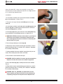
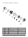
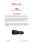
Explorer
CO2 SENSOR
USER MANUAL
© Hollis (2014)
1
Doc. 12-4127 r01 (2/28/14)
CO2 SENSOR
CONTENTS
NOTICES......................................................................................................................................................................3
DANGERS, WARNINGS, CAUTIONS, & NOTES..........................................................................................................3
DANGERS....................................................................................................................................................................4
WARNINGS..................................................................................................................................................................4
CO2 SENSOR OPERATION..........................................................................................................................................5
ASSEMBLY....................................................................................................................................................................6
DISASSEMBLY..............................................................................................................................................................7
DRYING SILICA BEADS FOR REUSE...........................................................................................................................7
CO2 SENSOR ASSEMBLY DIAGRAM...........................................................................................................................8
RECORDS....................................................................................................................................................................9
NOTES..........................................................................................................................................................................9
© Hollis (2014)
2
Doc. 12-4127 r01 (2/28/14)
CO2 SENSOR
NOTICES
LIMITED WARRANTY
For details, refer to the Product Warranty section on the Hollis web site: www.HollisGear.com
COPYRIGHT NOTICE
This operating manual is copyrighted, all rights are reserved. It may not, in whole or in part, be copied, photocopied, reproduced, translated,
or reduced to any electronic medium or machine readable form without prior consent in writing from Hollis.
Explorer CO2 Sensor User Manual, Doc. No. 12-4127
© Hollis, 2014
San Leandro, CA USA 94577
(510)729-5110
TRADEMARK, TRADE NAME, AND SERVICE MARK NOTICE
HOLLIS, the HOLLIS logo type, and Hollis Explorer are registered and unregistered trade-marks, trade names, and service marks of HOLLIS.
All rights are reserved.
DANGERS, WARNINGS, CAUTIONS, AND NOTES
Pay attention to the following symbols when they appear throughout this document. They denote important information and tips.
! D
ANGERS: are indicators of important information that if ignored would lead to
severe injury or death.
! W
ARNINGS: are indicators of important information that if ignored could lead
to severe injury or death.
! CAUTIONS: are indicators of information that if ignored may lead to minor to
moderate injury.
! N
OTES: indicate tips and advice that can inform of features, aid assembly, or
prevent damage to the product.
© Hollis (2014)
3
Doc. 12-4127 r01 (2/28/14)
CO2 SENSOR
!
DANGERS
!
The CO2 Sensing Module should NOT be used to determine absorbent duration. It is critical that you have
read (section 3.14 and 6.1 of the Explorer User Manual, doc. 12-4102), read this Explorer CO2 Sensor User
Manual, understood, and been trained in its proper use.
The Explorer rebreather scrubber is a maximum two hour duration scrubber when used under sport diving conditions. Under no circumstances should it be used for more than two hours. See Part 4 Section
2 "CO2 Absorbent Scrubber Pack" of the Explorer User Manual, doc. 12-4102, for further information on
duration times.
At this time, the CO2 Sensing Module is ONLY tested and known to be safe for use in the Hollis Explorer
rebreather.
Improper use or abuse (outside of the intended purpose) of this device can lead to serious harm or death.
!
WARNINGS
!
As with all underwater life support equipment, improper use or misuse of this product could cause serious injury or death.
There are many risks in rebreather diving. Education, preparation, and diving well within your skill level
are your best means to safely pursue this sport.
DO NOT attempt to disassemble, repair, or adjust the CO2 Sensor (P/N 25429). Doing so could cause malfunction resulting in serious injury or death. It will also void the limited warranty.
The CO2 sensor MUST be calibrated in accordance with the instructions in section 3.14 of the Explorer
User Manual (doc. 12-4102), before use.
This is an electronic device, and like all electronic devices this device can fail. Always carry adequate
bailout gas for the dive. If you feel symptoms of CO2 poisoning, bail out regardless of what the electronics
read.
© Hollis (2014)
4
Doc. 12-4127 r01 (2/28/14)
CO2 SENSOR
CO2 SENSOR OPERATION
The Explorer CO2 sensor is intended for use in detecting channeling, high work rates, bad absorbent material, and other possible
failures of the Explorer scrubber system. When used properly, this
accessory can add another safeguard to the use of your Explorer.
This manual is intended to be used in conjunction with the Explorer User Manual (doc. # 12-4102). Proper installation, calibration,
and use of your new CO2 Sensor is critical. This manual covers
proper assembly and maintenance of the CO2 sensor assembly.
For proper use of the CO2 sensor with the Explorer, see the Explorer User Manual.
! W
ARNING: You must read and understand the Explorer
User Manual (doc. # 12-4102), this manual, and have received an appropriate Hollis Certified user-training course
before use of this CO2 sensor.
The CO2 sensor used in the Explorer is an NDIR (Non-Dispersive
Infrared Sensor). It relies on an optical path to measure the
concentration of CO2 within the breathing loop. Water vapor can
condense on the optical elements of the sensor blocking the infrared signal the sensor uses, resulting in false CO2 readings. Hollis
uses indicating silica gel (7) beads to prevent moisture inside
the Explorer breathing loop from interfering with the CO2 sensor
readings in this way. This system though effective relies on the
user inspecting and replacing the silica beads on a regular basis.
The silica gel material is spherical in shape, 2 to 4 mm in diameter.
Hollis supplies 30 grams of silica beads (7) in an air tight container with this kit. This is enough to fill the CO2 sensor cap (10)
five times. Though the beads may be dried for reuse, see the
section "Drying Silica Beads For Reuse".
The silica beads (7) are an amber color when ready for use
in your Explorer (Fig. 1). When the silica beads (7) are saturated with moisture they turn an emerald green color. With the
Explorer the silica beads should be changed with dried or new
silica beads every 4-6 hours of use or whenever the beads have
changed to emerald green, whichever occurs first.
! N
OTE: 4-6 hours is a recommendation for most conditions. Different environments and use may require more frequent silica
bead inspection to avoid false CO2 readings during the dive.
Fig. 1
The silica beads (7) will absorb moisture from the surrounding
environment. To keep your silica beads (7) dry and ready for
use they should be stored in an airtight container. For conve-
© Hollis (2014)
5
Doc. 12-4127 r01 (2/28/14)
CO2 SENSOR
nience, the whole CO2 sensor cap assembly can may be removed from the sensor module and stored in an airtight container (i.e. ziplock bag) between dives.
ASSEMBLY
1. If not already installed, press the smaller diameter white filter
(8) into the cap (10), as shown (Fig. 2).
2. Then press the larger diameter white filter (6) into the cap
cover (5).
Fig. 2
3. If not already installed, install lightly lubricated O-rings (9 & 11)
onto the cap (10), see the diagram at the end of this manual for
individual O-ring (9 & 11) location.
4. Fill the cap (10) with 6 grams of fresh or dried silica beads (7)
(to an estimated 1/16 inch below the rim), as shown (Fig. 3).
! WARNING: NEVER use broken silica beads in your Explorer
CO2 sensor cap. Doing so could lead to obstructed gas
flow, rendering the CO2 sensor ineffective in detecting dangerous levels of CO2 gas.
Fig. 3
5. Press the cap cover (5) onto the cap (10).
6. Remove the sensor module according to instructions in the Explorer User Manual (doc. # 12-4102), Part 2 Section 3 "Complete
Disassembly & Reassembly.
7. Having removed the sensor module, inspect the mini-jack connector, and carefully wipe clean with a soft cloth.
Fig. 4
8. Press the CO2 sensor onto the mini-jack.
! D
ANGER: ONLY the Hollis CO2 sensor may be used with the
Explorer. No other CO2 sensors are tested or approved.
9. Fit the now filled cap (10) assembly onto the sensor module
(Fig. 4).
10. Reinstall the sensor module following the directions in the Explorer User Manual (doc. # 12-4102), Part 2 Section 3 "Complete
Disassembly & Reassembly.
! D
ANGER: After CO2 SENSOR (12) replacement into the
sensor module, you must ensure the unit is calibrated by
completing a full pre-dive sequence on the Explorer unit.
© Hollis (2014)
6
Doc. 12-4127 r01 (2/28/14)
CO2 SENSOR
DISASSEMBLY
1. Remove the sensor module according to instructions in the Explorer User Manual (doc. # 12-4102), Part 2 Section 3 "Complete
Disassembly & Reassembly.
2. Pull the cap (10) assembly off of the sensor module (Fig. 5).
3. Pull the CO2 sensor (12) off of the mini-jack.
4. Having removed the CO2 sensor (12), inspect the mini-jack
connector, and carefully wipe clean with a soft cloth.
Fig. 5
5. Remove the cap cover (5) from the cap (10) (Fig. 6).
6. Empty the silica beads (7). Inspect for broken or damaged
beads; discard if found. Otherwise, you may follow the instructions
in the section "Drying Silica Beads For Reuse" to dry the beads for
reuse.
7. Remove the O-rings (9 & 11) from the cap (10). Inspect for any
signs of deterioration. Discard if found.
Fig. 6
8. Visually inspect the white filters (6 & 8) to ensure they are intact
and their pores are not clogged. Remove and discard if clogged or
damaged. Otherwise, they may remain installed for reuse.
DRYING SILICA BEADS FOR REUSE
Silica beads (7) can simply be replaced with new or dried for
reuse. To dry silica beads (7) Hollis recommends heating in an
oven at 225˚ F for about an hour (times vary depending on your
oven). When the granules return to their original amber color,
they are ready for use in the Explorer. Avoid rapid hydration due
to liquid water exposure or rapid dehydration of the silica beads
(7). Any silica beads (7) that have become broken due to liquid
exposure, rapid drying, harsh handling; etc. must be discarded
and replaced.
! WARNING: Rapid hydration (i.e. breathing loop flooding) or
dehydration of the silica gel beads can cause them to fracture. NEVER use broken silica beads in your Explorer CO2
sensor cap. Doing so could lead to obstructed gas flow,
rendering the CO2 sensor ineffective in detecting dangerous levels of CO2 gas.
© Hollis (2014)
7
Doc. 12-4127 r01 (2/28/14)
Co 2 Sensor assembly Diagram
12
11
10
9
8
7
6
5
DIA.
P/N
DESCRIPTION
5
25522
CAP COVER
6
25687
FILTER
7
TBD
SILICA BEADS, INDICATING
8
25686
FILTER
9
25646
O-RING
10
25425
CAP
11
25644
O-RING
12
25429
CO2 SENSOR
© Hollis (2014)
NOTES
8
supersedes P/N 25427
Doc. 12-4127 r01 (2/28/14)
CO2 SENSOR
RECORDS
CO2 SENSOR SERIAL NUMBER:
DATE OF PURCHASE:
HOLLIS DEALER:
DEALER PHONE NUMBER:
NOTES:
San Leandro, CA USA 94577
(510)729-5110
www.hollisgear.com
E-mail: [email protected]
© Hollis (2014)
9
Doc. 12-4127 r01 (2/28/14)