1
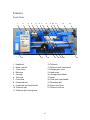
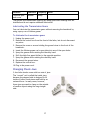
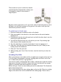
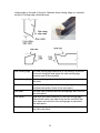
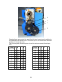
The premier source of parts and accessories for mini lathes and mini mills. Mini Lathe User’s Guide from LittleMachineShop.com Copyright © 2002, LittleMachineShop.com All rights reserved. Some photos Copyright © 2002, Frank J. Hoose, Jr. All rights reserved. Frank J. Hoose Jr. of Mini-Lathe.com took many of the photographs in this document. Be sure to visit the Mini-Lathe.com Web site, which has a wealth of information about the mini lathe. LittleMachineShop.com http://www.littlemachineshop.com 396 W Washington Blvd #500 • Pasadena CA 91103 (800) 981-9663 • [email protected] 2 Contents Introduction ................................................................................5 Specifications ..............................................................................5 Safety Considerations .....................................................................5 Features .....................................................................................6 Front View ...............................................................................6 Rear View ................................................................................7 Basic Accessories...........................................................................7 Cleaning .....................................................................................7 Mounting Your Lathe ......................................................................7 Operating Controls ........................................................................8 Motor Controls ...........................................................................8 High/Low Speed Shifter ................................................................9 Power Feed Forward/Neutral/Reverse Lever ..................................... 10 Power Feed Lever ..................................................................... 10 Carriage Hand Wheel ................................................................. 10 Cross Slide Feed Handle .............................................................. 10 Compound Rest Feed Handle ........................................................ 11 Compound Rest Rotation ............................................................. 11 Tailstock Lock Nut .................................................................... 11 Tailstock Quill Hand Wheel .......................................................... 11 Tailstock Quill Locking Lever ........................................................ 11 Adjustments .............................................................................. 12 Carriage ................................................................................ 12 Cross Slide Gibs........................................................................ 12 Cross Slide Nut ........................................................................ 13 Compound Rest Gibs .................................................................. 13 Apron Position ......................................................................... 13 Half Nuts ............................................................................... 14 Lead Screw Mounting ................................................................. 14 Drive Belt............................................................................... 14 Lubrication................................................................................ 15 Lubricating the Transmission Gears ................................................ 17 Changing Chuck Jaws.................................................................... 17 Grinding Tool Bits ........................................................................ 18 Grinding Tool Bits ..................................................................... 20 Grind the Front Relief ................................................................ 20 3 Grind the Left Side Relief ............................................................ 20 Grind the Top Rake ................................................................... 20 Round the Nose ........................................................................ 20 Adjusting Tool Bit Height ............................................................... 20 Turning .................................................................................... 21 Manual Turning ........................................................................ 21 Turning with Power Feed ............................................................ 22 Facing ..................................................................................... 22 Turning Angles ........................................................................... 23 Threading ................................................................................. 24 Change Gears .......................................................................... 24 Threading Dial ......................................................................... 27 Tool Bit ................................................................................. 28 Compound Angle ...................................................................... 28 Setting the Cutting Tool ............................................................. 29 Threading Process ..................................................................... 30 Common Accessories .................................................................... 30 Cut-Off Tool Holder ................................................................... 30 Quick Change Tool Post .............................................................. 31 Indexable Turning Tools .............................................................. 32 4-Jaw Chuck ........................................................................... 32 Faceplate ............................................................................... 33 Centers and Dogs ...................................................................... 33 Steady Rest and Follower Rest ...................................................... 34 Maintenance .............................................................................. 34 Cleaning ................................................................................ 35 Motor Brushes.......................................................................... 35 4 Introduction This user’s guide covers the 7x10 and 7x12 mini lathes that are sold by Grizzly Industrial, Harbor Freight Tools, Homier Mobile Merchants, Micro-Mark, Northern Tool & Equipment, Enco, and Wholesale Tool. These lathes are made in China, in several different factories, but to a similar set of plans. The general operating principles covered in this document are common to all of them. Specifications The following specifications are common to these lathes. Metric Lathes Inch Lathes Swing over bed 180 mm 7” Between Centers 200 mm / 300 mm 7.9” / 11.8” Spindle Taper 3 Morse taper 3 Morse taper Tailstock taper 2 Morse taper 2 Morse taper Spindle Bore 20 mm 0.79” Cross Slide Travel 65 mm 2.56” Compound Rest Travel 55 mm 2.17” Spindle Speed 100–2500 RPM 100–2500 RPM Automatic Feed Rate 0.1 mm / Revolution 0.004”/ Revolution Screw Threads 0.4–2.0 mm in 10 steps 12–52 TPI in 18 steps Safety Considerations Always use common sense when using a power tool. Review the safety instructions that came with your lathe. Besides the general safety rules for any power tool, the following are specific considerations for the mini lathe. Your mini lathe is just that, a mini, or small lathe. Don’t attempt jobs that are beyond its capacity. Check the work piece after you place it in the chuck or other work holding device. Be sure it is secure before turning on the lathe. Don’t wear loose clothing or jewelry when operating the lathe. 5 Features Front View 1 2 3 4 5 14 6 7 8 15 9 10 11 16 1. Headstock 2. Motor controls 3. 3-jaw chuck 4. Bed ways 5. Carriage 6. Tool post 7. Cross slide 8. Compound rest 9. Compound rest feed handle 10. Tailstock quill 11. Tailstock quill locking lever 12 13 17 18 19 20 12. Tailstock 13. Tailstock quill hand wheel 14. Change gear cover 15. Lead screw 16. Carriage hand wheel 17. Apron 18. Cross slide feed handle 19. Threading dial 20. Power feed lever 21. Tailstock lock nut 6 21 Rear View 1 2 1. High/low speed shifter 2. Power feed forward/neutral/reverse lever Basic Accessories The following accessories come with most mini lathes. Some mini lathes come with additional accessories. Chuck key for the 3-jaw chuck Outside jaws for the 3-jaw chuck Change gears: 30, 35, 40 (2), 45, 50, 55, 57, 60 and 65 teeth Hex wrenches: 3, 4, 5, and 6 mm Open end wrenches: 8 x 10 mm and 14 x 17 mm Cleaning Your lathe will arrive coated with grease to protect it from corrosion during shipment. Follow this procedure to remove the grease: 1. Wipe most of the grease off with rags or paper towels. 2. Clean the surfaces with mineral spirits (paint thinner). 3. Coat the surfaces with oil. See the lubrication section for specific recommendations for lubricants. Mounting Your Lathe All mini lathes come with rubber feet that attach to the same holes used to secure the lathe for shipping. If you want your lathe to be portable, simply install these feet. 7 Note: If your lathe didn’t come with them, adding chip tray braces (LittleMachineShop.com part number 1328) spreads the feet by several inches and makes the lathe much steadier. You can also bolt your lathe to your workbench. The following diagram shows the holes required. The wider bolt pattern is for the 7x12 lathe, while the narrower bolt pattern is for the 7x10 lathe. Mount the lathe to the workbench with 6 mm bolts. The bolts should be about 10 mm longer than the thickness of the workbench. Use fender washers on the underside of wooden benches to prevent the bolt heads from pulling through. Operating Controls There are several controls used to operate the lathe. Become familiar with them before you use the lathe. Motor Controls 1 2 1. Speed control 2. Forward/off/reverse switch 3. Power switch 8 3 There are several versions of the control panel on the mini lathe, but they all include the same controls. In some cases the power switch is a big red “emergency” switch, and in some cases it is a rocker switch. The big red emergency switch latches in the off position when you press the big red button. To turn the switch on, slide the big red button in the direction of the arrow. The big red button will swing up to the on position. The power switch interrupts the input power to the speed control circuit board. The forward/off/reverse switch switches the polarity of the speed control circuit board output power between the speed control circuit board and the motor. You control the motor speed by adjusting a potentiometer that provides the speed setting value to the speed control circuit board. On some lathes there is a safety switch on the speed control potentiometer that forces you to return the control to minimum speed when starting the lathe. CAUTION: Always turn the speed control to the minimum speed position before starting the lathe. Starting the lathe with the speed control set to a higher speed can damage the speed control circuit board. To power up the lathe: 1. Turn the speed control to the minimum speed position. 2. Place the forward/off/reverse switch in the off position. 3. Turn on the power switch. To start the lathe: 1. Ensure that the speed control is set to the minimum speed position. 2. Move the forward/off/reverse switch to the appropriate position. 3. Advance the speed control to the desired speed. To stop the lathe: 1. Turn the speed control to the minimum speed position. 2. Move the forward/off/reverse switch to the off position. 3. If you want to power down the lathe, press the big red switch or the rocker switch to turn off the power. High/Low Speed Shifter The high/low speed shifter is on the back of the headstock. It selects the spindle speed range. Low speed range 50*–1100 RPM High speed range 50*–2500 RPM * Minimum speed varies. 9 Never move this lever when the lathe is turning. You might need to turn the spindle slightly by hand as you move the high/low speed shifter. Power Feed Forward/Neutral/Reverse Lever The power feed forward/neutral/reverse lever controls the direction of rotation of the lead screw. When this lever is in the forward, or top, position the lead screw moves the carriage toward the headstock. When this lever is in the reverse, or bottom, position, the lead screw moves the carriage away from the headstock. In the center, or neutral, position the lead screw is disengaged and does not turn. There is a strong spring in this lever. Pull out firmly on the end of the lever while moving it. NOTE: In many cases the detents for this control are not well formed, and in some cases are not in the correct position. If your power feed will not stay engaged, or if it does not disengage properly, inspect the detents in the back of the headstock and move or enlarge them with a center punch. Power Feed Lever The power feed lever locks the half nuts around the lead screw, which engages the power feed. The power feed is engaged when this lever is down, and disengaged when this lever is up. Carriage Hand Wheel The carriage hand wheel moves the carriage toward or away from the headstock, depending on which way it is turned. Use this hand wheel to position the carriage. Because this hand wheel moves the carriage quickly it is not easy to use this hand wheel to move the carriage while you are turning. You cannot turn this hand wheel when the automatic feed is engaged. Cross Slide Feed Handle The cross slide feed handle moves the cross slide across the ways. Use this handle to advance the tool into the work and for facing cuts. The dial on this handle indicates the relative position of the cross slide. The graduated dial can be repositioned for convenience. On some lathes there are 40 divisions on the dial. On these lathes, each turn of the handle advances the cross slide 1 mm or approximately 0.040”. The distance is actually 0.03937”, an error of a little less than 2%. Other lathes have 50 graduations on the dial. On these lathes, each turn of the handle advances the cross slide 0.050”. 10 Compound Rest Feed Handle The compound rest feed handle advances or retracts the compound rest. Use this handle to advance the tool into the work. The dial on this handle indicates the relative position of the cross slide. The graduated dial can be repositioned for convenience. On some lathes there are 40 divisions on the dial. On these lathes, each turn of the handle advances the compound rest 1 mm or approximately 0.040”. The distance is actually 0.03937”, an error of a little less than 2%. Other lathes have 50 graduations on the dial. On these lathes, each turn of the handle advances the compound rest 0.050”. Compound Rest Rotation The compound rest rotates on the cross slide and you can position it at any angle. Position the compound rest so it moves parallel to the ways to make precise facing cuts. Position the compound rest at 29.5 degrees for cutting standard threads. To change the angle of the compound rest: 1. Using the compound rest feed handle, retract the compound rest until the locking socket head cap screws are exposed. 2. Loosen the two socket head cap screws. 3. Turn the compound rest to the desired angle. 4. Tighten the two socket head cap screws. NOTE: Use a protractor between the compound rest and the cross slide. Don’t depend on the die cast or plastic protractor that’s on the side of the compound rest on some lathes. Tailstock Lock Nut The tailstock is locked into position on the ways by the tailstock lock nut. Use a 15 mm wrench to tighten the tailstock lock nut. Tailstock Quill Hand Wheel The tailstock quill hand wheel moves the tailstock quill in and out. Most mini lathes have rather poor graduations on the top of the quill that show how far it is extended. Retract the tailstock quill all the way to remove tools from the taper in the tailstock quill. Tailstock Quill Locking Lever The tailstock quill locking lever keeps the tailstock quill from moving. Use the tailstock quill locking lever to lock the tailstock quill in position when you are 11 turning between centers. Turn the lever clockwise to lock the tailstock quill, and counterclockwise to unlock the tailstock quill. Adjustments Keeping your lathe in adjustment is an ongoing process. You should check all the following adjustments when you set up your lathe and then periodically as you use your lathe. Carriage The carriage is held on the ways by two adjustable retaining plates that are bolted to the bottom of the carriage. There are several fasteners in the carriage retainers. The socket head cap screws are used to adjust the position of the retainers. The setscrews and lock nuts lock the adjustments in place. To adjust the carriage retainers: 1. Remove the right lead screw mounting bracket. 2. Disconnect the apron by removing the two socket head cap screws through the front of the carriage. 3. Slide the apron to the right and off the lead screw. 4. Loosen all the fasteners on both retainers. 5. Snug the socket head cap screws so the carriage can move, but without play. 6. Snug the setscrews. Do not over tighten or you might break the retainers. 7. While holding the setscrews from turning, tighten the lock nuts. 8. Replace the apron. 9. Replace the right lead screw mounting bracket. Cross Slide Gibs A gib is a strip of metal placed between the bearing surface of two machine parts to ensure a precision fit and provide adjustment for wear. The mini lathe has gibs in several places, including the cross slide. To adjust the cross slide gibs: 1. 2. 3. 4. 5. 6. Loosen the three lock nuts on the side of the cross slide. Slightly loosen all three setscrews on the side of the cross slide. Snug each setscrew equally. This will lock the cross slide in position. Loosen each setscrew 1/8 turn to allow the cross slide to move. While holding the setscrews from turning, tighten the lock nuts. Test by turning the handle. Loosen or tighten all the setscrews the same amount until the cross slide moves freely, but without play in the dovetail. 12 Cross Slide Nut The cross slide nut is adjustable to remove free play from the cross slide feed handle. The three screws in the top of the cross slide adjust the cross slide nut. The two outer screws tip the nut off horizontal to reduce the endplay in the threads. The center screw locks the adjustment in place. To adjust the cross slide nut: 1. Loosen all three screws. 2. Back the cross slide all the way away from the center of the lathe, until it just contacts the dial. 3. Tighten the center screw until the feed handle becomes hard to turn. 4. Loosen the center screw until the feed handle just turns freely. 5. Tighten the near screw until the feed handle becomes hard to turn. 6. Loosen the near screw until the feed handle just turns freely. 7. Snug, but do not tighten the far screw. Compound Rest Gibs The compound rest also incorporates a gib for adjustment. To adjust the compound rest gibs: 1. 2. 3. 4. 5. 6. Loosen the three lock nuts on the side of the compound rest. Slightly loosen all three setscrews on the side of the compound rest. Snug each setscrew equally. This will lock the compound rest in position. Loosen each setscrew 1/8 turn to allow the compound rest to move. While holding the setscrews from turning, tighten the lock nuts. Test by turning the handle. Loosen or tighten all the setscrews the same amount until the compound rest moves freely, but without play in the dovetail. Apron Position The apron is adjustable to center the half nuts horizontally on the lead screw. To adjust the apron position: 1. Loosen the two socket head cap screws that secure the apron to the carriage. They are at the front edge of the carriage. 2. Engage the half nuts on the lead screw. 3. Tighten the two socket head cap screws. 13 Half Nuts There are two adjustments for the half nuts. The half nut gibs take the play out of the half nuts. The half nut closing limit stops the half nuts from closing too tightly on the lead screw. To adjust the half nut gibs: Tighten the three setscrews in the back edge of the apron to remove play from the half nuts. To adjust the half nut limit: 1. Loosen the lock nut on the bottom of the half nuts. 2. Adjust the setscrew until the half nuts close without binding on the lead screw. 3. While holding the setscrew from turning, tighten the lock nut. Lead Screw Mounting The brackets that mount the lead screw can move slightly to ensure that the lead screw does not bind in the half nuts. To adjust the right lead screw mounting bracket: 1. 2. 3. 4. 5. 6. Remove the tailstock by sliding it off the end of the ways. Loosen the two mounting socket head cap screws on the right bracket. Move the carriage as far to the right as possible. Engage the half nuts on the lead screw. Tighten the bracket mounting socket head cap screws. Replace the tailstock. To adjust the left lead screw mounting bracket: 1. Remove the change gear cover. 2. Loosen the locking nut on the change gear adjuster. 3. Loosen the two mounting socket head cap screws on the left lead screw bracket. 4. Move the carriage as far to the left as possible. 5. Engage the half nuts on the lead screw. 6. Tighten the bracket mounting socket head cap screws. 7. Tighten the locking nut on the change gear adjuster. 8. Replace the change gear cover. Drive Belt The drive belt needs to be aligned correctly or it will wear on one side or the other. 14 To adjust the drive belt: 1. 2. 3. 4. Unplug the power cord. Remove the motor cover from the back of the lathe. Remove the change gear cover. Remove the control box from the front of the lathe, but do not disconnect any wires. 5. Loosen all the lock nuts on the front of the lathe. 6. Back off the top and bottom set screws a couple turns. 7. Make sure that nothing will get into the change gear drive. 8. Make sure the control box is in a safe but accessible position. 9. Plug in the power cord. 10. Reach around to the back of the lathe and hold the motor. 11. Turn the motor on at slow speed. 12. While the motor is running, move the motor to a position where the belt has sufficient tension and does not rub either side of the pulley. 13. Tighten the nuts on the two studs that are aligned horizontally. 14. Snug the setscrews that are aligned vertically. 15. Turn off the motor. 16. Tighten the lock nuts. 17. Replace the control box. 18. Replace the change gear cover. 19. Replace the motor cover. Lubrication We recommend the use of two lubricants on your lathe. Where oil is required, we recommend Mobil 1 synthetic motor oil. Mobil 1 far exceeds the lubrication needs of the mini lathe, and maintains a good surface film between applications. Where grease is required, we recommend Lubriplate 630-AA lithium (white) grease. Lithium grease is a plastic-friendly grease that is easy to find and easy to use. 15 The following points on your lathe require lubrication. Location Lubricant Frequency Notes Lathe ways Oil Daily Apply oil to both the front and back ways on both sides of the carriage. Move the carriage back and forth to spread the oil. Lead screw threads Oil Daily Clean swarf (chips, shavings, and debris) daily. Compound rest dovetail Oil Daily Advance the compound rest to the extent of its normal travel. Apply oil to the end of the gib and the ends of the dovetails. Retract the compound rest. Cross slide dovetail Oil Daily Advance the cross slide to the extent of its travel. Apply oil to the end of the gib and the ends of the dovetails. Retract the cross slide. Lead screw bushings Oil Weekly There is an oil fitting on the top of each one. Remove the change gear cover to lubricate the left bushing. Other machined surfaces Oil Weekly Oil lubricates and prevents corrosion. Chuck Oil Monthly Disassemble, clean and lubricate. Wrap with a paper towel, secure with an elastic band, and run lathe to sling out excess oil. Cross slide feed screw Grease Yearly Compound rest feed screw Grease Yearly Lead screw drive gears and bushings Grease Yearly Also lube change gears as you use them. Transmission gears Grease Yearly See procedure below for lubricating the transmission gears without removing the headstock. Carriage hand wheel drive gears Grease Yearly 16 Location Lubricant Frequency Notes Tailstock quill and screw Grease Yearly The spindle and countershaft bearings are deep groove ball bearings that are shielded and do not require additional lubrication. Lubricating the Transmission Gears You can lubricate the transmission gears without removing the headstock by using a spray can of lithium grease. To lubricate the transmission gears: 1. Unplug the power cord. 2. Remove the control box from the front of the lathe, but do not disconnect any wires. 3. Remove the screw or screws holding the ground wires to the front of the headstock. 4. Insert the lithium grease can’s spray tube into one of the open holes. 5. Spray the grease while rotating the chuck by hand. 6. Shift the high/low speed shifter to the opposite position. 7. Spray the grease while rotating the chuck by hand. 8. Reconnect the ground wires. 9. Replace the control box. 10. Plug in the power cord. Changing Chuck Jaws 3-Jaw lathe chucks come with two sets of jaws. The “normal” set is called the inside jaws, because the stepped side is designed to fit inside of hollow work pieces and hold by an outward force. In many cases, however, these jaws are used to clamp on the outside of smaller objects using the long straight side. 17 The second set of jaws is called the outside jaws because the stepped side of these jaws is designed to clamp on the outside of larger objects. Because of the construction of a 3-jaw chuck, each of the three jaws in a set is different. You will find a number in the groove in the side of each jaw that identifies its position in the set. To install a set of chuck jaws: 1. Place the three jaws in numeric order on the bench. 2. Slide jaw number 1 into the slot in the chuck that has the serial number stamped in it. 3. Press the jaw into the slot with one hand, and with the other hand, turn the chuck key to open the chuck. 4. You will feel the jaw move out in the slot as you turn. Stop turning right after the jaw clicks inward in the slot. 5. Turn the chuck key to close the chuck about ¼ turn to engage jaw 1. 6. Slide jaw 2 into the next slot counterclockwise from jaw 1 when you are looking toward the headstock. 7. Slide jaw 3 into the open slot. 8. While pressing jaws 2 and 3 into the slots, turn the chuck key to close the chuck. Grinding Tool Bits When you purchase a new lathe tool bit, it might have an angle on the end, but it is not properly sharpened for turning. Grinding lathe tool bits is a bit of an art. It takes some practice to get good at it. You need to create a cutting edge that is sharp, extends out so that the cutting edge and not the side of the tool contacts the work, but that still has enough support to maintain sufficient strength to cut metal. Before diving in, there are some terms you need to understand. The illustration below shows these terms. First, notice that there are two cutting edges on the tool bit. There is a cutting edge on the end of the tool bit called the front cutting edge. There is also a 18 cutting edge on the side of the tool. Between these cutting edges is a rounded section of cutting edge called the nose. Side Cutting Edge The side cutting edge does most of the cutting. As the too bit moves along the work piece the side cutting edge removes most of the material. Front Cutting Edge The front cutting edge cuts when the tool is advanced into the work. Nose The nose is a critical part of the cutting edge, because it produces the surface finish of the work piece. Side Rake The side rake produces the side cutting edge that cuts into the work piece. Side Relief Side relief provides clearance for the side cutting edge. Without side relief, the side of the tool bit would hit the work piece and not allow the cutting edge to penetrate the work piece. Back Rake The back rake produces the front cutting edge that cuts into the work piece. 19 Front Relief Front relieve provides clearance for the front cutting edge. Without front relief, the front of the tool bit would hit the work piece and not allow the cutting edge to penetrate the work piece. How to Grind Tool Bits Use a bench grinder to sharpen your tool bits. Even an inexpensive bench grinder can do a good job grinding lathe tool bits. In some cases, you might want to purchase a higher quality fine grit wheel. Keep a small cup of water near your grinder. Grinding generates heat, which can cause two problems. The tool bit will become too hot to hold. Overheating can also affect the heat treatment of the tool bit, leaving the cutting edge soft. Use a protractor to measure the angles. They are not super-critical, but you should try to stay within one degree of the recommendations. Grind the Front Relief The first step in creating a tool bit is to grind the front relief. For most work, a relief angle of 10° works well. While you are grinding the front relief, you are also creating the front cutting edge angle. Make this angle about 10° also, so that the corner formed by the front cutting edge and the side cutting edge is less than 90°. Grind the Left Side Relief Form the left side relief next. Again, create about a 10° angle. You don’t need to form a side cutting angle. The side cutting edge can be parallel to the side of the tool blank. Grind the Top Rake The top of the tool bit is ground at an angle that combines the back rake and the side rake. The side rake is most important, because the side cutting edge does most of the work. For cutting steel and aluminum, the side rake should be about 12° and the back rake should be about 8°. For cutting brass, the rake angles should be much less, or even 0°. Round the Nose A small nose radius allows you to turn into tight corners. A large nose radius produces better surface finishes. Create a nose radius that is appropriate for the tool bit you are creating. Adjusting Tool Bit Height The cutting edge of the tool bit should almost always be set to the center height of the lathe spindle. 20 There are several methods for checking the height of the tool bit. Perhaps the simplest way is to place a thin strip of metal, such as a steel rule or feeler gage, between the work piece and the point of the tool bit. If the height is correct, the strip of metal will be held vertical. If the top is leaning toward you, the tool bit is too low. If the top is leaning away from you, the tool bit is too high. Using the standard tool post, you adjust the tool bit height using shims under the tool bit. You can get an economical set of shims, about the right size, at any auto parts store. Purchase a set of feeler gages and remove the pivot pin. The easy way to adjust the tool bit height is to get a quick change tool post. Virtually all quick change tool posts incorporate a mechanism for easily adjusting the tool bit height. Turning The most common use of a lathe is turning down the diameter of a work piece. Manual Turning Follow these steps to turn the outside diameter of a work piece. To turn manually: 1. Put a tool bit in the tool holder and adjust the cutting edge to center height. 2. Angle the tool so that the front cutting edge forms an acute angle with the axis of the work piece, as shown in the illustration below. 3. Move the carriage so that the tool bit is near the right end of the work piece. 4. Turn the lathe on. Adjust the speed to an appropriate speed for the material and diameter you are working on. The LittleMachineShop.com Web site has a calculator to help you determine appropriate cutting speeds. 5. Using the cross slide feed handle, slowly advance the tool bit into the work until it just touches the surface of the work piece. 21 6. Move the carriage to the right so that the tool bit is past the end of the work piece. 7. Using the cross slide feed handle, advance the tool bit about 0.010”. 8. Using the carriage hand wheel, move the carriage slowly to the left. As the tool bit meets the work piece, it starts cutting. Turning with Power Feed The mini lathe incorporates a power carriage feed that can move the carriage either direction. This same power feed is used for turning and threading. For turning, the change gear train is configured with 20 tooth gears in positions A and C, and 80 tooth gears in positions B and D. This is the way the lathe comes from the factory, and is how you should reset it after threading. If you haven’t changed the gearing, this is the way your lathe is configured. To turn with power feed: 1. Put a tool bit in the tool holder and adjust the cutting edge to center height. 2. Angle the tool so that the front cutting edge forms an acute angle with the axis of the work piece, as shown in the illustration above. 3. Move the carriage so that the tool bit is near the right end of the work piece. 4. Move the power feed forward/neutral/reverse lever to the forward position. 5. Turn the lathe on. Adjust the speed to an appropriate speed for the material and diameter you are working on. The LittleMachineShop.com Web site has a calculator to help you determine appropriate cutting speeds. 6. Using the cross slide feed handle, slowly advance the tool bit into the work until it just touches the surface of the work piece. 7. Move the carriage to the right so that the tool bit is past the end of the work piece. 8. Using the cross slide feed handle, advance the tool bit about 0.010”. 9. Push down on the power feed lever until the half nuts engage. As the tool bit meets the work piece, it starts cutting. 10. When the carriage has moved as far as you want, raise the power feed lever to disengage the half nuts. The carriage stops. NOTE: Be sure to move the power feed forward/neutral/reverse lever to the neutral position when you have completed the turning operation. Facing Facing is cutting on the end (or face) of the work piece. 22 To face a work piece: 1. Put a tool bit in the tool holder and adjust the cutting edge to center height. 2. Angle the tool so that the side cutting edge forms an acute angle with the face of the work piece. 3. Move the carriage to the right so that the tool bit is past the right end of the work piece. 4. Ensure that the power feed forward/neutral/reverse lever is in the neutral position. 5. Push down on the power feed lever until the half nuts engage. You might have to move the carriage slightly so the half nuts will engage. 6. Turn the lathe on. Adjust the speed to an appropriate speed for the material and diameter you are working on. The LittleMachineShop.com Web site has a calculator to help you determine appropriate cutting speeds. 7. Using the compound rest feed handle, slowly advance the tool bit into the work until it just touches the surface of the work piece. 8. Move the cross slide back so that the tool bit is clear of the diameter of the work piece. 9. Using the compound rest feed handle, advance the tool bit about 0.005”. 10. Using the cross slide feed handle, advance the cross slide slowly. As the tool bit meets the work piece, it starts cutting. 11. Continue advancing the cross slide until the tool bit reaches the center. Turning Angles There are several methods of turning angles or tapers. For large angles of short length, such as a chamfer, turn the compound rest to the angle you want. Advance the tool across the work with the compound rest, and advance the tool into the work with the cross slide or the carriage. You can use the same method for small angles (usually called tapers) of a length less than the compound rest travel. For longer tapers, the work is usually placed between centers with the tail center offset from the centerline of the lathe. 23 Chamfer Taper Threading Much of the mechanism of your lathe is provided to allow you to cut threads. Your lathe can cut a broad range of thread pitches. In fact, with the standard change gears, you can cut many more thread pitches than those shown on the table on the lathe. Change Gears The series of gears that drive the lead screw are called change gears because you change them to turn different thread pitches. There are 4 positions for the change gears, commonly called A, B, C and D. A This is the top change gear position. When you received your lathe it had a 20 tooth metal gear in this position. B Gear positions B and C are on the same shaft, between positions A and D. Position B is the inside gear on this shaft. When you received your lathe it had an 80 tooth plastic gear in this position. C Gear positions B and C are on the same shaft; between positions A and C. Position C is the outside gear on this shaft. When you received your lathe it had a 20 tooth metal gear in this position. D Position D is the end of the lead screw. When you received your lathe it had an 80 tooth plastic gear in this position. 24 A B C D Changing these gears varies the speed that the lead screw turns in relation to the speed that the spindle turns. This allows you to cut threads with different numbers of threads per inch. The following table shows the gears to use for various common threads per inch. Threads A per inch B C D Threads A per inch B C D 12 40 Any Any 30 26 40 Any Any 65 13 40 65 30 28 20 Any Any 35 14 40 Any Any 35 32 20 Any Any 40 16 40 Any Any 40 36 20 Any Any 45 18 40 Any Any 45 38 20 50 19 40 50 57 40 57 B50 20 Any Any A 20 40 Any Any 50 44 20 Any Any 55 22 40 Any Any 55 48 20 Any Any 60 24 40 Any Any 60 52 20 Any Any 65 60 60 25 60 For normal turning, use the following gears. A B C D 20 80 20 80 The change gears are commonly tight on the shaft when new. You might need to use a screwdriver behind them to pry them off. Gear positions B and C are on a hollow shaft that comes off easily when the retaining socket head cap screw is removed. Then you can use an arbor press to remove the gears from the hollow shaft. Be careful that you do not lose the key. Gear position D has a spacer behind the gear. When you only use three gears, put the spacer on outside the gear so the gear will align with the gear in position B. In the change gear chart, many of the combinations have “Any” in column B. This means that you can use a gear with any number of teeth in position B. It is an idler and does not affect the overall gear ratio. Use a gear that makes it easy to properly engage the gears. For these combinations, you can use any gear for position C; this gear acts only as a spacer and does not engage the other gears. To change the gears: 1. Using a 4 mm hex wrench, remove the change gear cover. 2. Using 4 mm and 5 mm hex wrenches, remove all three retaining socket head cap screws from the ends of the shafts. 3. Use a 10 mm end wrench to loosen the nut that is on the back end of the shaft in position B-C. This allows the B-C shaft to move in the adjustment slot. 4. Use a 14 mm end wrench to loosen the nut on the arc below and behind the gear in position D. This allows the entire bracket on which the B-C shaft mounts to swing down. 5. Remove all the gears. 6. If you will be using three gears, remove the spacer behind the D position gear from the end of the lead screw. Be careful that you do not lose the key. 7. Replace the gears with the gears shown in the chart for the threads per inch that you want to cut. 8. If you will be using three gears, replace the spacer outside the D position gear on the end of the lead screw. Be sure to insert the key. 9. If you are using three gears, place any gear in position C to act as a spacer. 10. Replace the three retaining socket head cap screws from the ends of the shafts. Snug, but do not tighten, until the gear train is adjusted. 11. Move the B-C shaft until all the gears are properly engaged. 26 12. Use a 14 mm end wrench to tighten the nut on the arc below and behind the gear in position D. 13. Use a 10 mm end wrench to tighten the nut that is on the back end of the shaft in position B-C. 14. Using 4 mm and 5 mm hex wrenches, tighten the three retaining socket head cap screws on the ends of the shafts. 15. Using a 4 mm hex wrench, replace the change gear cover. Threading Dial When cutting screw threads on a lathe, you must make multiple cutting passes to cut the threads to full depth. The threading dial helps you align the cutting tool with the emerging thread before you start a cutting pass. The gear on the bottom of the threading dial’s shaft engages the lead screw. The dial turns when the half nuts are not engaged with the lead screw. When the half nuts are engaged, the carriage moves and the threading dial stops turning. The gear on the threading dial has 16 teeth, and the lead screw has 16 threads per inch, so each revolution of the threading dial represents one inch of motion of the carriage. Each of the eight divisions on the dial represents 1/8” of motion. If you are cutting 16 threads per inch, you can engage the half nuts when the threading dial is on any line. Since a line represents 1/8” of travel, it will always align with a thread groove. If you are cutting 13 threads per inch, you must only engage the half nuts when the threading dial is at 1. Since 13 and 16 have no common factors but 1, you must only engage the half nuts at even inch increments of motion. The following table shows where you can engage the half nuts for various threads per inch. Threads per inch Dial divisions Threads per inch Dial divisions 12 1, 3, 5, 7 14 1, 5 13 1 16 Any 27 Threads per inch Dial divisions Threads per inch Dial divisions 18 1, 5 32 Any 19 1 36 1, 3, 5, 7 20 1, 3, 5, 7 38 1, 5 22 1, 5 40 Any 24 Any 44 1, 3, 5, 7 26 1, 5 48 Any 28 1, 3, 5, 7 52 1, 3, 5, 7 Tool Bit For threading, the tool bit is ground to the profile of the thread. For most threads, this is a point with a 60° included angle. The front of the tool should have about 10° of relief. No back rake is used. The left side should have about 8° of relief, and the right side should have about 10° of relief. The tip of the tool should have a flat that is 1/8 of the thread pitch. Compound Angle Set the compound rest at a 29.5° angle from a line perpendicular to the axis of the lathe. This allows you to advance the tool with the compound rest. At this angle the tool cuts only on the left side of the thread form. This helps prevent chatter that might result from cutting the entire V form of the thread at once. It is best to use an accurate protractor when setting the compound rest. The protractor on the lathe is not accurate enough. 28 Setting the Cutting Tool Even though the compound rest is set at an angle to the work piece, the thread cutting tool must be set square to the work piece. A center gage makes this setting possible. A center gage has several V-shaped cutouts. They can be used to check the tool bit as you grind it, and to check the angle of the tool with respect to the work piece. To align the tool bit to the work: 1. Ensure that the point of the tool bit is set at the center height of the lathe. 2. Place the center gage between the point of the tool bit and the work piece. Leave enough room so that the center gage can be moved back and forth so you can check each side of the tool bit separately. 3. Align the tool bit to the sides of the V-shaped cutout in the side of the center gage. 4. Secure the tool bit in position. 29 5. Advance the tool bit until the point just makes contact with the work piece. 6. Zero the cross slide dial. Hold the cross slide feed handle and rotate the graduated dial. Threading Process It takes several passes to cut a thread to full depth. You must follow the correct procedure during each pass to ensure the thread is cut correctly. Use the power feed forward/neutral/reverse lever to engage the lead screw drive. The carriage should move from right to left (toward the head stock) to cut right-hand threads, or from left to right (away from the head stock) to cut left-hand threads. For each pass in cutting threads: 1. Move the carriage to the beginning of the cut. 2. Advance the cross slide to the initial position. For the first pass, you are already there. For additional passes, advance it 2 complete turns to the 0 mark. 3. Advance the compound rest to move the tool bit into the work. For the first pass, this should be only 0.001”. For additional passes, it should be 0.005 to 0.010”. 4. Start the lathe. Run it at the lowest speed that develops sufficient torque to make the cut. 5. When the threading dial reaches an appropriate mark, engage the half nuts. Note that you must be right on the mark. The half nuts will also engage half way between each mark, but this will ruin your thread. 6. When the tool reaches the end of the thread, disengage the half nuts. 7. Back off the cross slide exactly 2 turns. After you have made the first pass, which should leave just a spiral mark on the work piece, use a thread gage to check that you are cutting the correct number of threads per inch. Use a nut or the matching part to tell when you are done cutting the thread. Common Accessories You will soon find that the purchase of a lathe is just an initial step. There are many tools and accessories that you will need to get full use from your lathe. As you might expect, LittleMachineShop.com carries a full selection of accessories. Following are some common accessories used with the mini lathe, a small sampling of the complete LittleMachineShop.com line. Cut-Off Tool Holder Cutting-off, or parting, is a common procedure on a lathe. Once you have turned a piece on the end of a rod, you use a cut-off tool to part the work from the rod. Cut-off tools come in various widths, from about 0.040” wide, to much 30 wider than can be used with a mini lathe. But most cut-off blades are ½” tall. This means that they will not fit in the tool post that comes with the mini lathe. The cut-off tool holder shown below fits in the standard tool post and holds a ½” tall cut-off blade. LittleMachineShop.com part number 1551. This cut-off tool holder fits in the standard 4-way tool post (and most other tool posts) and holds 1/2" tall cut-off blades. Quick Change Tool Post The standard mini lathe tool post has positions for up to four tools. While this is useful, the standard mini lathe tool post does not have the capability to hold boring bars or cut-off tools without an adapter of some sort. Quick-change tool posts provide several advantages. They provide an easy way to adjust the height of the tool bit. They provide a quick way to change from one tool to the other. They provide a way to hold several different kinds of tools, usually including turning tools, cut-off blades, and boring bars. And they are indexable, meaning that you can remove a tool, and when you replace it, it returns to the same position, with no adjustment necessary. LittleMachineShop.com part number 1672. This is a very high quality quickchange tool post for the mini lathe. It holds tools up to 3/8" shank. The set includes: Tool post Turning tool holder Turning and boring tool holder Boring bar holder Multi tool holder Cut-off tool holder 31 Indexable Turning Tools Indexable turning tools usually come in a set of five tools, providing a range of cutting angles. These tools use indexable inserts, usually made from carbide, but sometimes from high-speed steel. They are called indexable because you can change an insert and the new insert will take the exact position of the insert it replaces. You can resume work with no further adjustments. Indexable inserts are pre-sharpened. LittleMachineShop.com part number 1669. This set of indexable turning tools includes 5 tools (AR, AL, BR, BL, TE), wrenches, and extra screws. It comes in a fitted case. (The letters designate the angles of the cutting edge.) 4-Jaw Chuck The 3-jaw scroll chuck that comes with the mini lathe provides a quick way to clamp round and hexagonal work fairly accurately. A 4-jaw independent chuck provides several advantages over a 3-jaw scroll chuck. It can hold square or rectangular work, as well as round. Work can be centered more accurately because you adjust each jaw independently. It can hold larger work than the same size 3-jaw chuck. You can offset work in a 4jaw chuck by clamping it off center. 32 LittleMachineShop.com part number 1175. 3 inch, 4-Jaw chuck. Each jaw is independently adjustable and reversible. This set includes a chuck key, reversible jaws, four M6x35 mounting studs and four hardened M6 nuts. It also includes a template to help you drill the mounting holes if your spindle has only three holes. The through bore of this chuck is 7/8". The chuck can hold work up to 80 mm (3.15") in diameter. Faceplate A faceplate allows you to mount work that can’t be held in a chuck. You can bolt odd-shaped workpieces to the faceplate. LittleMachineShop.com part number 1199. Faceplate for the Mini Lathe. The faceplate is 6.25" in diameter and has 8 slots for mounting work. Centers and Dogs A live center goes in the tailstock and is used to support the end of a long work piece; it rotates with the workpiece. A dead center goes in the spindle and supports work being turned between two centers. A lathe dog is used to drive work being turned between centers. 33 The live center is LittleMachineShop.com part number 1189. It has a 2 Morse taper shank. This center fits the tailstock of the mini lathe. The dead center is LittleMachineShop.com part number 1188. It has a 3 Morse taper shank. This center fits the headstock of the mini lathe. The center has a 60 degree included point angle. The lathe dog is LittleMachineShop.com part number 1149. This lathe dog has a capacity of just over 3/8". Steady Rest and Follower Rest Steady and follower rests support small diameter work that would otherwise flex too much. A steady rest mounts in a fixed position on the ways of the lathe. A follower rest mounts on the carriage and moves with the cutting tool, providing support where it is needed. The steady rest is LittleMachineShop.com part number 1197. The steady rest can support work up to 1.5" in diameter. The follower rest is LittleMachineShop.com part number 1198. Maintenance Maintenance of the mini lathe is simple, but important. Regular maintenance will keep your mini lathe working like new for many years. 34 Cleaning The maintenance you perform most often is cleaning. Keeping swarf (chips, shavings, and debris) off of wearing surfaces is the most important thing you can do to prolong the life of your mini lathe. Use a 1” paintbrush to remove swarf from the ways as you work. Clean the lead screw before each use. Clean swarf from the lathe, from top down after each use. Motor Brushes The motor brushes can be replaced without removing the motor. Follow these steps. 1. Unplug the power cord. 2. Unscrew the motor brush retainer from the front side of the motor through the hole in the frame of the lathe. 3. Replace the front motor brush. 4. Replace the front motor brush retainer. 5. Remove the motor cover from the back of the lathe. 6. Unscrew the motor brush retainer from the back of the motor. 7. Replace the back motor brush. 8. Replace the back motor brush retainer. 9. Replace the motor cover. 35