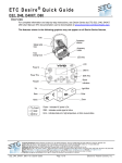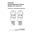
1
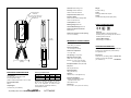
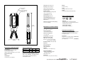
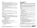
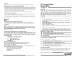
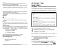
OPERATION
Please make sure that you have already read and fully understand the WARNING section on page 1.
Making Measurements with the AC Current Probe Model JM813.
• Connect the black and red terminals to the Ampere AC range of your DMM or current measuring
instrument. Select the appropriate current range (5 A AC). Clamp the probe around the conductor to be
tested. If the reading is less than 2 A, select the lower range until you obtain the best resolution. Read
the value display on the DMM and multiply it by the probe ratio (1000/1). (If reading = 0.592 A AC, the
current flowing through the probe is 0.592 A x 1000 = 592A AC).
• For best accuracy: carefully center the conductor inside the probe jaw, avoid if possible, the proximity
of other conductors which may create noise.
Tips for Making Precise Measurements
• When using a current probe with a meter, it is important to select the range that provides the best
resolution. Failure to do this may result in measurement errors.
• Make sure that probe jaw mating surfaces are free of dust and contamination. Contaminants cause air
gaps between the jaws, increasing the phase shift between primary and secondary. It is very critical for
power measurement.
MAINTENANCE:
AC Current Probe
Model JM813
User Manual
DESCRIPTION
The JM813 (Catalog #2110.93) is designed for use in industrial environments. The “squared” jaws permit
multiple conductor or bus bar positioning. The current output makes it the perfect tool for measurement
with DMMs, recorders, power and harmonic meters. The Model JM813 is compatible with any AC
ammeter, multimeter, or other current measuring instrument with an input impedance lower than 0.6Ω. To
achieve the stated accuracy, use the JM813 with the DMM having an accuracy of 0.75%.
WARNING
These safety warnings are provided to ensure the safety of personnel and proper operation of the
instrument.
• Read the instruction manual completely and follow all the safety information before attempting
to use or service this instrument.
• Use caution on any circuit: Potentially high voltages and currents may be present and may
pose a shock hazard.
Warning
• For maintenance use only original factory replacement parts.
• To avoid electrical shock, do not attempt to perform any servicing unless you are qualified to do so.
• To avoid electrical shock and/or damage to the instrument, do not get water or other foreign agents
into the probe.
Maintenance
To ensure optimum performance, it is important to keep the probe jaw mating surfaces clean at all times.
Failure to do so may result in error in readings. The following is the recommended procedure for cleaning
the probe jaws; Use a very fine sand paper (fine 600) to avoid scratching the jaw, then gently clean with a
soft oiled cloth.
REPAIR AND CALIBRATION
You must contact our Service Center for a Customer Service Authorization number (CSA#). This will
ensure that when your instrument arrives, it will be tracked and processed promptly. Please write the CSA#
on the outside of the shipping container. If the instrument is returned for calibration, we need to know if you
want a standard calibration, or a calibration traceable to N.I.S.T. (includes calibration certificate plus
recorded calibration data).
Chauvin Arnoux®, Inc. d.b.a. AEMC® Instruments
15 Faraday Drive • Dover, NH 03820 USA
Tel:
(800) 945-2362 (Ext. 360)
(603) 749-6434 (Ext. 360)
Fax:
(603) 742-2346 or (603) 749-6309
[email protected]
(Or contact your authorized distributor)
Costs for repair, standard calibration, and calibration traceable to N.I.S.T. are available.
NOTE: All customers must obtain a CSA# before returning any instrument.
TECHNICAL AND SALES ASSISTANCE
If you are experiencing any technical problems, or require any assistance with the proper use or
application of this instrument, please call our technical hotline:
(800) 343-1391 • (508) 698-2115 • Fax (508) 698-2118
Chauvin Arnoux®, Inc. d.b.a. AEMC® Instruments
[email protected]
www.aemc.com
• Read the Safety Specifications section prior to using the current probe. Never exceed the
maximum voltage ratings given.
• Safety is the responsibility of the operator.
• ALWAYS connect the current probe to the display device before clamping the probe onto the
sample being tested.
• ALWAYS inspect the instrument, probe, probe cable, and output terminals prior to use.
Replace any defective parts immediately.
• NEVER use the current probe on electrical conductors rated above 600 V in overvoltage
category III (CAT III). Use extreme caution when clamping around bare conductors or bus bars.
INTERNATIONAL ELECTRICAL SYMBOLS
This symbol signifies that the current probe is protected by double or reinforced insulation. Use
only factory specified replacement parts when servicing the instrument.
This symbol signifies CAUTION! and requests that the user refer to the user manual before
using the instrument.
This is a type A current sensor. This symbol signifies that application around and removal
from HAZARDOUS LIVE conductors is permitted.
DEFINITION OF MEASUREMENT CATEGORIES
Cat. I: For measurements on circuits not directly connected to the AC supply wall outlet such as
protected secondaries, signal level, and limited energy circuits.
Cat. II: For measurements performed on circuits directly connected to the electrical distribution system.
Examples are measurements on household appliances or portable tools.
Cat. III: For measurements performed in the building installation at the distribution level such as on
hardwired equipment in fixed installation and circuit breakers.
Cat. IV: For measurements performed at the primary electrical supply (<1000V) such as on primary
overcurrent protection devices, ripple control units, or meters.
RECEIVING YOUR SHIPMENT
Upon receiving your shipment, make sure that the contents are consistent with the packing list. Notify
your distributor of any missing items. If the equipment appears to be damaged, file a claim immediately
with the carrier and notify your distributor at once, giving a detailed description of any damage.
Shop for AEMC products online at:
99-MAN 100115.v5 06/07
www.ShopAEMC.ca
1.877.766.5412
®
Overload: 3600 A during 5 mn
Accuracy: Per IEC 185-26-27
Class 0.5 from 48 to 1000 Hz
Ø=2.52" (64 mm)
Cable max.
Ampere Second Product: 90 A.s
1.97 x 5.31" (50 x 135 mm) or
2.52 x 3.94" (64 x 100 mm)
Bus Bar max.
Frequency Range:
30 Hz to 5 kHz; current derating above
1 kHz for continuous use
Weight:
2.65 lbs. (1200 g)
Colors:
Dark gray handles with red jaws
Output:
Two standard safety banana jacks (4mm)
Load Impedance: ≤ 0.6Ω
Working Voltage: 600 V AC
SAFETY SPECIFICATIONS
Common Mode Voltage: 600 V AC
Influence of Adjacent Conductor:
0.005 A/A AC
Influence of Conductor in Jaw Opening:
1% ± 0.1 A of reading
12.40"
(315 mm)
P1
MECHANICAL SPECIFICATIONS
ELECTRICAL SPECIFICATIONS
Current Range:
1 to 2400 A AC, continuous cycle for
the full temperature range
(3000 A if ambient temperature < 35°C or 95°F)
Transformation Ratio:
3000:3
Output Signal:
1 mA AC/A AC (3 A at 3000 A)
Shop for AEMC products online at:
150A
1.5%
1.5°
600A
0.75%
0.75°
3000A
0.5%
0.5°
(*Reference conditions: 23°C±3°K, 20 to 85%
RH, 48 to 65 Hz, external magnetic field < 40
A/m, no DC component, no external current
carrying conductor, test sample centered.)
Load impedance 0.55Ω.
www.ShopAEMC.ca
Accessories:
Leads, set of 2, 5 ft safety (1000V) ...Cat #2111.29
Mechanical Shock:
100 g (IEC 68-2-27)
Accuracy and Phase Shift*:
Primary current
Accuracy %
Phase shift
Jaw Opening: 3.54" (90 mm)
Drop Test:
500 mm (IEC 68-2-32)
S2
1.877.766.5412
Current Probe JM813......................Cat #2110.93
Includes a user manual and a product warranty
and registration card
Envelope Protection: IP 20 (IEC 529)
Black
S1
ORDERING INFORMATION
Influence of Temperature:
< 0.1% per 10°K
Maximum Conductor Size:
Cable: 2.52" ∅ max. (64mm)
Bus bar: 1.97 x 5.31" (50 x 135 mm)
2.52 x 3.94" (64 x 100 mm)
1.89"
(48 mm)
Red
Common Mode Voltage:
600V Category III, Pollution: 2
Operating Temperature:
14° to 122°F (-10° to 50°C)
P2
Storage Temperature:
-13° to 176°F (-25° to 80°C)
4.72"
(120 mm)
Electrical:
Double insulation or reinforced insulation
between primary or secondary and outer case of
handle upon IEC 1010-2-32
Vibration:
10/55/10 Hz, 0.15 mm (IEC 68-2-6)
Polycarbonate Material:
Handles: 10% fiberglass charged
polycarbonate UL 94 V0
Jaws: ABS UL 94 V2
Dimensions:
4.72 x 12.40 x 1.89" (120 x 315 x 48 mm)
Lead No. 211 for Probe 5A Series
(5 ft. rated 250 V)..............................Cat #2950.06
Overload: 3600 A during 5 mn
Weight:
2.65 lbs. (1200 g)
Accuracy: Per IEC 185-26-27
Class 0.5 from 48 to 1000 Hz
Ø=2.52" (64 mm)
Cable max.
Colors:
Dark gray handles with red jaws
Ampere Second Product: 90 A.s
1.97 x 5.31" (50 x 135 mm) or
2.52 x 3.94" (64 x 100 mm)
Bus Bar max.
Output:
Two standard safety banana jacks (4mm)
Frequency Range:
30 Hz to 5 kHz; current derating above
1 kHz for continuous use
Load Impedance: ≤ 0.6Ω
SAFETY SPECIFICATIONS
Working Voltage: 600 V AC
Common Mode Voltage: 600 V AC
Influence of Adjacent Conductor:
0.005 A/A AC
Influence of Conductor in Jaw Opening:
1% ± 0.1 A of reading
12.40"
(315 mm)
P1
MECHANICAL SPECIFICATIONS
ORDERING INFORMATION
ELECTRICAL SPECIFICATIONS
Current Range:
1 to 2400 A AC, continuous cycle for
the full temperature range
(3000 A if ambient temperature < 35°C or 95°F)
Transformation Ratio:
3000:3
Output Signal:
1 mA AC/A AC (3 A at 3000 A)
Jaw Opening: 3.54" (90 mm)
Accessories:
Leads, set of 2, 5 ft safety (1000V) ...Cat #2111.29
Lead No. 211 for Probe 5A Series
(5 ft. rated 250 V)..............................Cat #2950.06
Drop Test:
500 mm (IEC 68-2-32)
S2
Mechanical Shock:
100 g (IEC 68-2-27)
Accuracy and Phase Shift*:
Primary current
Accuracy %
Phase shift
Includes a user manual and a product warranty
and registration card
Envelope Protection: IP 20 (IEC 529)
Black
S1
Current Probe JM813......................Cat #2110.93
Influence of Temperature:
< 0.1% per 10°K
Maximum Conductor Size:
Cable: 2.52" ∅ max. (64mm)
Bus bar: 1.97 x 5.31" (50 x 135 mm)
2.52 x 3.94" (64 x 100 mm)
1.89"
(48 mm)
Red
Common Mode Voltage:
600V Category III, Pollution: 2
Operating Temperature:
14° to 122°F (-10° to 50°C)
P2
Storage Temperature:
-13° to 176°F (-25° to 80°C)
4.72"
(120 mm)
Electrical:
Double insulation or reinforced insulation
between primary or secondary and outer case of
handle upon IEC 1010-2-32
150A
1.5%
1.5°
600A
0.75%
0.75°
3000A
0.5%
0.5°
(*Reference conditions: 23°C±3°K, 20 to 85%
RH, 48 to 65 Hz, external magnetic field < 40
A/m, no DC component, no external current
carrying conductor, test sample centered.)
Load impedance 0.55Ω.
Vibration:
10/55/10 Hz, 0.15 mm (IEC 68-2-6)
Polycarbonate Material:
Handles: 10% fiberglass charged
polycarbonate UL 94 V0
Jaws: ABS UL 94 V2
Dimensions:
4.72 x 12.40 x 1.89" (120 x 315 x 48 mm)
Shop for AEMC products online at:
www.ShopAEMC.ca
1.877.766.5412
OPERATION
Please make sure that you have already read and fully understand the WARNING section on page 1.
Making Measurements with the AC Current Probe Model JM813.
• Connect the black and red terminals to the Ampere AC range of your DMM or current measuring
instrument. Select the appropriate current range (5 A AC). Clamp the probe around the conductor to be
tested. If the reading is less than 2 A, select the lower range until you obtain the best resolution. Read
the value display on the DMM and multiply it by the probe ratio (1000/1). (If reading = 0.592 A AC, the
current flowing through the probe is 0.592 A x 1000 = 592A AC).
• For best accuracy: carefully center the conductor inside the probe jaw, avoid if possible, the proximity
of other conductors which may create noise.
Tips for Making Precise Measurements
• When using a current probe with a meter, it is important to select the range that provides the best
resolution. Failure to do this may result in measurement errors.
• Make sure that probe jaw mating surfaces are free of dust and contamination. Contaminants cause air
gaps between the jaws, increasing the phase shift between primary and secondary. It is very critical for
power measurement.
MAINTENANCE:
User Manual
DESCRIPTION
The JM813 (Catalog #2110.93) is designed for use in industrial environments. The “squared” jaws permit
multiple conductor or bus bar positioning. The current output makes it the perfect tool for measurement
with DMMs, recorders, power and harmonic meters. The Model JM813 is compatible with any AC
ammeter, multimeter, or other current measuring instrument with an input impedance lower than 0.6Ω. To
achieve the stated accuracy, use the JM813 with the DMM having an accuracy of 0.75%.
WARNING
These safety warnings are provided to ensure the safety of personnel and proper operation of the
instrument.
• Read the instruction manual completely and follow all the safety information before attempting
to use or service this instrument.
• Use caution on any circuit: Potentially high voltages and currents may be present and may
pose a shock hazard.
Warning
• For maintenance use only original factory replacement parts.
• To avoid electrical shock, do not attempt to perform any servicing unless you are qualified to do so.
• To avoid electrical shock and/or damage to the instrument, do not get water or other foreign agents
into the probe.
Maintenance
To ensure optimum performance, it is important to keep the probe jaw mating surfaces clean at all times.
Failure to do so may result in error in readings. The following is the recommended procedure for cleaning
the probe jaws; Use a very fine sand paper (fine 600) to avoid scratching the jaw, then gently clean with a
soft oiled cloth.
REPAIR AND CALIBRATION
You must contact our Service Center for a Customer Service Authorization number (CSA#). This will
ensure that when your instrument arrives, it will be tracked and processed promptly. Please write the CSA#
on the outside of the shipping container. If the instrument is returned for calibration, we need to know if you
want a standard calibration, or a calibration traceable to N.I.S.T. (includes calibration certificate plus
recorded calibration data).
Chauvin Arnoux®, Inc. d.b.a. AEMC® Instruments
15 Faraday Drive • Dover, NH 03820 USA
Tel:
(800) 945-2362 (Ext. 360)
(603) 749-6434 (Ext. 360)
Fax:
(603) 742-2346 or (603) 749-6309
[email protected]
(Or contact your authorized distributor)
Costs for repair, standard calibration, and calibration traceable to N.I.S.T. are available.
NOTE: All customers must obtain a CSA# before returning any instrument.
TECHNICAL AND SALES ASSISTANCE
If you are experiencing any technical problems, or require any assistance with the proper use or
application of this instrument, please call our technical hotline:
(800) 343-1391 • (508) 698-2115 • Fax (508) 698-2118
Chauvin Arnoux®, Inc. d.b.a. AEMC® Instruments
[email protected]
www.aemc.com
Shop for AEMC products online at:
AC Current Probe
Model JM813
www.ShopAEMC.ca
1.877.766.5412
99-MAN 100115.v5 06/07
• Read the Safety Specifications section prior to using the current probe. Never exceed the
maximum voltage ratings given.
• Safety is the responsibility of the operator.
• ALWAYS connect the current probe to the display device before clamping the probe onto the
sample being tested.
• ALWAYS inspect the instrument, probe, probe cable, and output terminals prior to use.
Replace any defective parts immediately.
• NEVER use the current probe on electrical conductors rated above 600 V in overvoltage
category III (CAT III). Use extreme caution when clamping around bare conductors or bus bars.
INTERNATIONAL ELECTRICAL SYMBOLS
This symbol signifies that the current probe is protected by double or reinforced insulation. Use
only factory specified replacement parts when servicing the instrument.
This symbol signifies CAUTION! and requests that the user refer to the user manual before
using the instrument.
This is a type A current sensor. This symbol signifies that application around and removal
from HAZARDOUS LIVE conductors is permitted.
DEFINITION OF MEASUREMENT CATEGORIES
Cat. I: For measurements on circuits not directly connected to the AC supply wall outlet such as
protected secondaries, signal level, and limited energy circuits.
Cat. II: For measurements performed on circuits directly connected to the electrical distribution system.
Examples are measurements on household appliances or portable tools.
Cat. III: For measurements performed in the building installation at the distribution level such as on
hardwired equipment in fixed installation and circuit breakers.
Cat. IV: For measurements performed at the primary electrical supply (<1000V) such as on primary
overcurrent protection devices, ripple control units, or meters.
RECEIVING YOUR SHIPMENT
Upon receiving your shipment, make sure that the contents are consistent with the packing list. Notify
your distributor of any missing items. If the equipment appears to be damaged, file a claim immediately
with the carrier and notify your distributor at once, giving a detailed description of any damage.
®