1
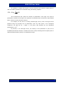
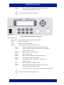
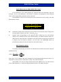
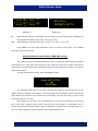
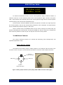
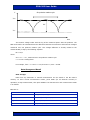
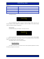
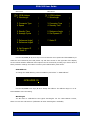
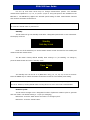
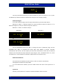
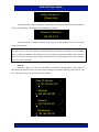
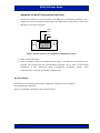
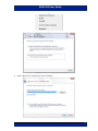
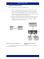
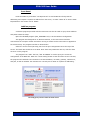
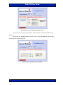
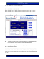
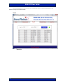
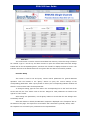
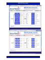
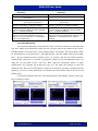
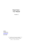
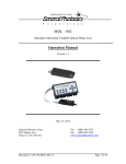
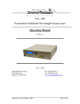
ERM-202
Single or Dual Channel
Polarization Extinction Ratio
Measurement System
User Guide
Version: 1.1
Date: May 21, 2015
ERM-202 User Guide
General Photonics, Incorporated is located in Chino California.
For more information visit the company's website at:
www.generalphotonics.com
or call 909-590-5473
GP-UM-ERM-202-11
Page 2 of 64
ERM-202 User Guide
SAFETY CONSIDERATIONS
The following safety precautions must be observed during operation of this product.
Failure to comply with these precautions or with specific warnings elsewhere in this manual
violates safety standards of design, manufacture, and intended use of the product. General
Photonics assumes no liability for customers’ failure to comply with these requirements.
Before operation, the user should inspect the product and review the manual carefully.
Properly ground the chassis and work space using the chassis ground terminal.
Use only in a safe work environment in terms of temperature, humidity, electrical power and risk
of fire or shock. The product is designed for indoor use. Avoid exposure to liquids or water
condensation. Provide adequate ventilation for cooling.
Operate the product on a stable surface. Avoid excess vibration.
Standard laser safety procedures should be followed during operation.
Never look into the light source fiber connector when the light source is
turned on. THE OUTPUT LIGHT FROM A HIGH POWER LASER IS HARMFUL
TO HUMAN EYES. Follow industry standard procedures when operating a
high power laser source.
GP-UM-ERM-202-11
Page 3 of 64
ERM-202 User Guide
GP-UM-ERM-202-11
Page 4 of 64
ERM-202 User Guide
Section 1.0
Overview ............................................................... 7
1.1 Principle of Operation.............................................................. 7
Section 2.0
Features ................................................................ 9
2.1 Front Panel and Optical Inputs ................................................ 9
2.2 Rear Panel: Electrical and Remote Control Interfaces ........... 11
Section 3.0
Operation Instructions ...................................... 13
3.1 Unpacking ............................................................................. 13
3.2 Front Panel Operation ........................................................... 13
3.3 Measurement Modes.............................................................. 15
PER/Power...................................................................................15
Two-Input Power Ratio Measurement (ERM-202-2 only) .............15
for PM coupler characterization....................................................15
ER Maximum/Minimum Search Mode (ERM-202-1 only) ..............16
Angle Measurement Mode (ERM-202-2 only) ...............................17
DOP Estimation Mode ...................................................................17
Manual Polarizer Control Mode (ERM-202-1 only) ........................18
3.4 Additional Features ............................................................... 19
Analog Monitor Voltage ................................................................19
Data Storage and Recall ...............................................................20
Setup Parameters ........................................................................21
3.5 Troubleshooting .................................................................... 29
Front Panel...................................................................................29
Remote Control ............................................................................29
Section 4.0
Specifications ..................................................... 31
Optical..........................................................................................31
Electrical ......................................................................................31
Physical and Environmental .........................................................31
GP-UM-ERM-202-11
Page 5 of 64
ERM-202 User Guide
Appendices ................................................................................. 33
Appendix 1.0 Remote Control Commands ................................... 33
Command Lists.............................................................................33
Appendix 2.0 RS-232 connection and setup ................................ 39
Appendix 3.0 USB connection and setup ..................................... 41
USB Driver Installation ................................................................41
Appendix 4.0 Ethernet setup....................................................... 47
Front Panel...................................................................................48
LabView program .........................................................................48
Appendix 5.0 GPIB setup and control.......................................... 52
GPIB control.................................................................................52
Appendix 6.0 LabView control program ...................................... 53
RS-232/USB/GPIB .......................................................................53
Ethernet .......................................................................................54
Program Interface........................................................................55
GP-UM-ERM-202-11
Page 6 of 64
ERM-202 User Guide
Section 1.0
Overview
General Photonics’ ERM-202 series of polarization extinction ratio (PER) meters provide
fast, accurate measurement of the polarization extinction ratio, polarization angle, and power of
input light beams. The dual channel version also automatically measures the coupling and power
ratios between the two channels. The instrument contains one or two optical measurement
modules, each consisting of a rotating polarizer driven by a motor.
(a)
(b)
Figure 1 (a) Dual and (b) single-channel polarization extinction ratio meters
1.1 Principle of Operation
Polarization extinction ratio (PER) is the ratio between the power in the principal
polarization component of a light beam and the power in the orthogonal polarization component,
expressed in dB. It is a measure of the linearity and degree of polarization of a polarized light
source, or of the polarization preserving or suppressing properties of a fiber or optical component.
A typical laboratory setup for measuring PER uses a rotating polarizer placed after the light source
under test, as shown in Figure 2.
Polarizer
Light Source
Photodetector
Light
Power meter
Figure 2 Laboratory ER measurement setup
GP-UM-ERM-202-11
Page 7 of 64
ERM-202 User Guide
The polarizer is rotated 360 degrees, and the maximum and minimum output power in
mW is recorded. The PER is then calculated using the following equation:
PER = 10 log10
Pmax
(dB)
Pmin
This measurement also yields the direction of polarization of the light. The angle of
polarization is defined as the angle of the polarizer’s transmission axis at maximum output optical
power, relative to some reference direction.
For example, for the case of a linearly polarized light source, most of the light will be
polarized along the principal axis of polarization, with very little power in the orthogonal
component. The PER can be > 40dB, i.e., the power ratio between the two orthogonal
polarizations is >104.
By contrast, in an ASE light source, the linearity of the polarization is poor due to
broadband spontaneous emission. Its PER will be close to 0dB, indicating that the optical power is
distributed approximately equally in all polarization angles.
GP-UM-ERM-202-11
Page 8 of 64
ERM-202 User Guide
Section 2.0
Features
2.1 Front Panel and Optical Inputs
The front panel of the ER meter is shown in Figure 3 and Figure 4. It contains the power
switch (Power), organic light-emitting diode display (OLED), push button control pads, and optical
input port(s). The input ports are free space, so they can accept either flat or angle polished input
fiber connectors (see function menu for connector type selection). For the standard 1260-1620nm
ER meter, input power should be between –30 and +10 dBm. If the input power is too low, the
screen will display “Optical Power Low!”
External fiber connectors should be cleaned using industry standard cleaning methods before
connection to the ERM-202. Dirty connectors can affect measurement accuracy.
Figure 3 Dual Channel ER meter front panel
Front panel features:
OLED display: displays data and operation mode information
Power:
power on/off switch
Input:
adapter for optical fiber input
Keypad:
push buttons for measurement status control
AUTO1:
Begins automatic PER measurement for channel 1
AUTO2:
Begins automatic PER measurement for channel 2
STOP 1:
Stops measurement for channel 1.
STOP 2:
Stops measurement for channel 2.
STORE:
Store currently displayed measurement values.
RECALL:
Recall stored measurement values.
LOCAL:
Returns the ER meter to front panel control from remote control.
FUNC:
Accesses operation parameter setup.
GP-UM-ERM-202-11
Page 9 of 64
ERM-202 User Guide
ENTER:
Enters measurement parameters set with arrow keys,
accesses alternate operation modes.
▲
◄ ►: Select and set measurement parameters.
▼
Figure 4 Single Channel ER meter front panel
Front panel features:
OLED display: displays data and operation mode information
Power:
power on/off switch
Input:
adapter for optical fiber input
Keypad:
push buttons for measurement status control
AUTO:
Begins automatic PER measurement (default setting)
CYCLE:
Set the number of polarizer rotation cycles for averaging
(default value is 1 cycle).
MANUAL:
Manual polarizer rotation control.
STOP:
Stops measurement.
STORE:
Store currently displayed measurement values.
RECALL:
Recall stored measurement values.
SPEED:
Set scanning time for one polarizer rotation cycle
(default is 0.4s)
FUNC:
Accesses operation parameter setup.
ENTER:
Enters measurement parameters set with arrow keys,
accesses alternate operation modes,
returns the ER meter to front panel control from remote control.
▲
◄ ►: Select and set measurement parameters.
▼
GP-UM-ERM-202-11
Page 10 of 64
ERM-202 User Guide
2.2 Rear Panel: Electrical and Remote Control Interfaces
The AC power plug, fuse, and communication interface connectors are mounted on the
rear panel, as shown in Figure 5.
The ERM-202 includes RS-232, USB, Ethernet, and GPIB interfaces for external computer
operation of the system. LabView™ (National Instruments, www.ni.com) control programs are
provided. Control commands, USB driver installation instructions, and instructions for running
control programs are located in the appendices.
Figure 5 ER meter rear panel
Rear Panel Features:
USB 2.0 interface port
Line: External AC input connector
RS-232 serial interface port
Cooling fan air intake
Ethernet interface port
: Chassis ground
GPIB interface port
SR30 4-pin connector: Analog interface port
Fuse location:
Figure 6 shows the location of the fuse compartment
under the power cord plug. There are two fuses in the
compartment- the one in use and a spare. The fuse
further inside the compartment is active. The one
closer to the compartment opening is the spare.
Replace the fuse with one with the exact rating of the
original. The ERM-202 uses a 3A/250VAC fuse.
Figure 6 Fuse compartment
GP-UM-ERM-202-11
Page 11 of 64
ERM-202 User Guide
GP-UM-ERM-202-11
Page 12 of 64
ERM-202 User Guide
Section 3.0
Operation Instructions
3.1 Unpacking
Inspect ERM-202 for any physical damage due to shipping and transportation. Contact
carrier if any damage is found. Check the packing list to see if any parts or accessories are
missing.
Packing List
Item #
Description
1
ERM-202
2
Power cord
3
RS-232 cable (straight-wired)
4
USB cable
5
SR30 to BNC connection cable for analog outputs
6
User guide
7
Software cd
3.2 Front Panel Operation
1.
Connect power cord and plug it into wall receptacle. Make sure the ground pin of the
power cord is connected to earth ground.
2.
Connect the device under test (DUT) to the ERM-202’s input port(s). The FC adapter has a
wide key slot on the top for flat (PC) connectors and a narrow key slot on the bottom for
angled (APC) connectors. Make sure the optical power level at the input connector is below
10 dBm (10.0 mW).
3.
Turn on the ER meter. It will begin automatic measurement using the default or previously
specified settings. To change selectable operation settings, see items under the
FUNCTIONS menu, as well as the SPEED and CYCLE settings (for ERM-202-1).
GP-UM-ERM-202-11
Page 13 of 64
ERM-202 User Guide
GP-UM-ERM-202-11
Page 14 of 64
ERM-202 User Guide
3.3 Measurement Modes
The ERM-202 has four measurement modes, as well as store/recall and setup functions. In
all measurement modes, a dual channel ER meter displays the measured PER for channels 1 and 2
on the left side of the screen. Depending on the selected mode, the right side of the screen
displays the measured power for each channel (this is the default mode), the power ratio between
channels 1 and 2, the angle of the major axis of the polarization ellipse (relative to a reference
angle) for each channel, or the estimated DOP for channels 1 and 2. The ENTER key is used to
cycle through the available measurement modes.
PER/Power
The default operation mode for the ERM-202 is automatic measurement. When the
instrument is turned on, it executes an initialization process, and then measures and displays the
real-time polarization extinction ratio (ER, in units of dB) and optical power (PWR, in units of mW
or µW), using the default measurement speed of 0.4s/cycle. The single-channel version also
displays the polarization angle θ, in degrees, relative to the reference angle θr. The default
reference angle 0.00° corresponds to the vertical direction. Both θ and θr are in the −90 to +90°
range.
1
2
XX.XX
ER
dB
XX.XX
PWR
mW
XX.XX
ER
dB
XX.XX
PWR
mW
ER: 24.83 dB
P: 0.502 mw
ERM-202-2
θ: 85.26
θr: 0.00
ERM-202-1
The STOP or STOP 1 and STOP 2 buttons stop the measurement processes for the
corresponding channels. The latest set of measured values will remain on the display. If only one
channel is subsequently started again, only that channel’s data will be updated.
Two-Input Power Ratio Measurement (ERM-202-2 only)
for PM coupler characterization
Press the ENTER key once from the default measurement mode to bring up the Two-Input
Power Ratio function. The left side of the screen continues to show the PER measurements for
channels 1 and 2, while the right side of the screen shows the coupling ratio of the PM coupler
under test on top and the power split ratio on the bottom:
GP-UM-ERM-202-11
Page 15 of 64
ERM-202 User Guide
1
2
ER:
XX.XX
XX.XX
ER
dB
ER
dB
XX.XX
P1 %
P1 + P2
XX.XX
P1/P2
Instantaneous ER value calculated from the maximum and minimum power measured in
the last polarizer rotation cycle. ER = 10*log (Pmax/Pmin)
P1/(P1+P2):
Coupling ratio of PM coupler under test, in %.
P1/P2:
Power split ratio between channels 1 and 2.
ER Maximum/Minimum Search Mode (ERM-202-1 only)
The ER meter’s automatic measurement mode correctly characterizes the worst-case ER of
a DUT using a broadband source. However, if a narrow-band laser source is used to measure the
ER of PM fiber, the instantaneous measured ER is not necessarily the worst-case (minimum) ER.
To measure the ER of a PM fiber with a narrow-band laser source, the fiber can be either
mechanically manipulated (stretched, bent, or moved) or temperature cycled. Either method will
cause variation in the instantaneous ER, allowing the worst-case value to be found. Temperature
cycling is the preferred method.
To facilitate this measurement, the ERM-202-1 has a maximum/minimum ER search
function. From auto mode, press ENTER once to access the maximum/minimum ER search
function.
ER: 20.45 dB
MAX: 22.68 MIN: 18.60
ER:
Instantaneous ER value calculated from the maximum and minimum power measured in
the last polarizer rotation cycle. ER = 10*log (Pmax/Pmin)
Max:
Maximum ER value measured within the current measurement period
Min:
Minimum ER value measured within the current measurement period
The measurement period begins when the max/min search mode is entered. To perform
an ER measurement using a narrow-band source, first connect the source → PM fiber under test →
ER meter. Put the ER meter into max/min search mode and either stretch or heat/cool the PM
fiber. The MIN value measured will be the worst-case ER.
To reset the measurement period, use the ENTER key to cycle through measurement
modes back to max/min mode.
GP-UM-ERM-202-11
Page 16 of 64
ERM-202 User Guide
Angle Measurement Mode (ERM-202-2 only)
In the ERM-202-2, this mode displays the measured PER and polarization angle for
channels 1 and 2. In the ERM-202-1, this function is included in the PER/Power mode described
earlier, which displays PER, polarization angle, and power.
Press ENTER once from the two-input power ratio measurement screen to begin the Angle
Measurement function.
1
2
ER:
XX.XX
ER
dB
XX.XX
θ
XX.XX
ER
dB
XX.XX
θ
Instantaneous PER value calculated from the maximum and minimum power reading from
the last polarizer rotation cycle. ER = 10*log (Pmax/Pmin)
θ:
Polarizer angle corresponding to the maximum power reading from the last polarizer
rotation cycle, measured relative to the reference angle. The default reference angle is 0°,
defined as the vertical direction. Polarization angle θ and reference angle θr are measured
in degrees, and will always be between −90° and +90°. See FUNCTIONS section for
information on setting the reference angle to a value other than 0°.
DOP Estimation Mode
For partially polarized light, the DOP can be estimated from the ER measurement using the
following formula:
ERmax
P − Pmin 10 10 − 1
DOP = max
= ERmax
Pmax + Pmin
10 10 + 1
where ERmax is the maximum ER value achievable by stretching/bending/moving the fiber or by
temperature cycling the fiber. Temperature cycling is the preferred method.
Press ENTER once from the angle measurement mode (ERM-202-2) or the ER max/min
search mode (ERM-202-1) to begin the DOP estimation function. The display will show:
GP-UM-ERM-202-11
Page 17 of 64
ERM-202 User Guide
1
2
XX.XX
ER
dB
XX.XX
XX.XX
ER
dB
XX.XX
ERM-202-2
ER:
DOP
%
DOP
%
ER: 4.76 dB
DOP(EST): 50.77%
`ERM-202-1
Instantaneous ER value calculated from the maximum and minimum power reading from
the last polarizer rotation cycle. ER = 10*log (Pmax/Pmin)
DOP:
Estimated DOP, calculated from DOP = [(10ER/10-1)/ (10ER/10+1)] *100
Press ENTER once from DOP estimation mode to return the ER meter to the default
automatic measurement mode.
Manual Polarizer Control Mode (ERM-202-1 only)
This function is used for manual alignment control. The polarizer rotation angle is manually
controlled from the front panel, with the power ratio measured at each step. Please note that the
angle display in manual mode is for estimation purposes only and should not be taken as a precise
angle measurement.
To enter manual control mode, press the MANUAL button.
Angle: (0010)*0.06
=00.60 deg
The minimum angle step size is 0.06°. Use the arrow keys to set the step size for the
rotation angle by changing the multiplier. The left and right arrows change the active (underlined)
digit, and the up and down keys increment the active digit. The step size range is 0.06° to 90°
(multiplier range is 1 to 1500).
After setting the step size, press the ENTER key to execute the selection. The first time
this is done after entering manual mode, the ER meter goes through an initialization step: a
minimum power measurement is taken, then the polarizer is rotated to the vertical position (0° if
θr is 0°) and the display shows the manual measurement display screen:
GP-UM-ERM-202-11
Page 18 of 64
ERM-202 User Guide
PR: 10.05 dB θ: 0.00
P: 0.239 mw θr: 0.00
In manual measurement mode, θ is the current polarizer angle, measured relative to
reference value θr, P is the measured power at the current polarizer angle, and PR is the power
ratio, in dB, between the measured power at the current polarizer angle and the minimum power
measured during the manual mode initialization step.
From this point, each time ENTER is pressed, the polarizer will rotate one angle step from
the current position, and the new measurement parameters will be displayed. The optical power
will be automatically scaled to display in mW or µW.
Once in manual mode, the MANUAL button can be used to change the rotation step size
without reinitializing the measurement. Pressing the ENTER key after the step size is changed will
then cause the polarizer to rotate by the new step size from the current position.
3.4 Additional Features
This section describes functions for external ER monitoring, data storage/recall, and
operational parameter setup.
Analog Monitor Voltage
The ERM-202 has analog monitor voltage outputs for all channels from the SR30 4-pin
connector on the rear panel. General Photonics provides a conversion cable to BNC connectors.
Channel 2
Analog output signal
GND (Ch2)
GND (Ch1)
Channel 1
Analog output signal
Figure 7 Analog output connector pinout (left), SR30 to BNC connection cable (right)
GP-UM-ERM-202-11
Page 19 of 64
ERM-202 User Guide
V
One polarizer rotation cycle
Vmax
ΔV
Vmin
time
The monitor voltage scales with the log of the measured power after the polarizer. The
PER can therefore be calculated from the difference between the maximum and minimum voltages
measured over one polarizer rotation cycle. This voltage difference is linearly related to the
measured PER (in dB) by the following equation:
ER = ΔV/s
where
ΔV = Vmax − Vmin, measured over one polarizer rotation cycle
s = 0.04 is a scaling factor
For example, if ΔV = 1 V and s = 0.04, then ER = 1/0.04 = 25 dB.
Data Storage and Recall
Data storage:
Data from any automatic or manual measurement can be stored in the ER meter’s
memory. To store current measurement results, press STOP (for all channels currently in
operation) to stop measurement, then press STORE. The data stored in each measurement mode
is as follows:
ERM-202-2:
Measurement mode
Data stored
PER/Power mode
ER1, power1, ER2, power2
Two-Input Power ratio
ER1, P1/(P1+P2), ER2, P1/P2
Angle measurement
ER1, θ1, ER2, θ2
DOP estimation mode
ER1, DOP1, ER2, DOP2
GP-UM-ERM-202-11
Page 20 of 64
ERM-202 User Guide
ERM-202-1:
Measurement mode
Data stored
Default auto mode
ER, power, angle, reference angle
Max/Min ER mode
ER, ER max, ER min
DOP estimation mode
ER, DOP
Manual mode
Power ratio, power, current polarizer angle, reference angle
The display will show:
Store ID: 01
Use the UP/DOWN keys (▲▼) to select the desired storage location. There are 100
storage locations (#0-99) available. The ENTER key stores the data to the selected storage
location and restarts automatic measurement.
Data retrieval:
To retrieve stored data, press RECALL. The display will show:
Recall ID: 01
Use the up and down arrow keys to select the desired storage location. Pressing ENTER
will display the data stored in that location. If there is no information stored at the selected
location, the display will show a “No Data” message.
Press RECALL again to return to recall ID selection.
Setup Parameters
The FUNC key allows the user to access and set various operational parameters. Pressing
the FUNC key brings up a set of menus:
GP-UM-ERM-202-11
Page 21 of 64
ERM-202 User Guide
ERM-202-2
ERM-202-1
1. GPIB Address
2. Wavelength
↓
1. GPIB Address
2. Wavelength
↓
3. Connector Type
4. Speed
↑
↓
3. Connector Type
4. Standby Time
↑
↓
5. Standby Time
6. Average Cycles
↑
↓
5. Reference Angle
6. Get Dynamic IP
↑
↓
7. Reference Angle1
8. Reference Angle2
↑
↓
7. Static IP
↑
9. Get Dynamic IP
10. Static IP
↑
Use the UP/DOWN (▲▼) arrow keys to move between menu options and the ENTER key to
select the one indicated by the hand pointer. Up and down arrows on the right side of the display
screen indicate whether additional menu options can be accessed by scrolling up or down. Most of
these parameter settings are written to memory and retained after power-down.
GPIB Address:
To change the GPIB address, press the FUNC key and select “1. GPIB Address”.
GPIB ADDR: 05
Use the UP/DOWN arrow keys (▲▼) to change the address. The address range is 1 to 30.
Press ENTER to save the setting.
Wavelength:
The ER meter is calibrated at two typical wavelengths. For the 1260-1620nm version,
these are 1310 nm and 1550 nm (calibration at other wavelengths is available).
GP-UM-ERM-202-11
Page 22 of 64
ERM-202 User Guide
To change the calibrated wavelength setting, press the FUNC key and select “2.
Wavelength”.
CH1 λ: 1550 nm
CH2 λ: 1550 nm
Wavelength Select
1550 nm
ERM-202-2
ERM-202-1
ERM-202-2: Use the LEFT/RIGHT arrow keys (◄►) to move between channel selection
and wavelength selection for a particular channel (the wavelength will be underlined). Use the
UP/DOWN arrow keys (▲▼) to select a channel or change the wavelength.
ERM-202-1: Use the UP/DOWN arrow keys (▲▼) to change the wavelength.
Press ENTER to execute the new settings. The instrument will begin measurement using
the new wavelength settings.
Connector type:
The ER meter can accept both flat (PC, upper key slot) and angle polished (APC, lower key
slot) optical connectors, and is set for PC by default.
Press FUNC and select “3. Connector Type”.
CH1 Type: PC
CH2 Type: PC
Connector Type
PC
ERM-202-2
ERM-202-1
ERM-202-2: Use the LEFT/RIGHT arrow keys (◄►) to move between channel selection
and connector type selection for a particular channel (the connector type will be underlined). Use
the UP/DOWN arrow keys (▲▼) to select a channel or change the connector type.
ERM-202-1: Use the UP/DOWN arrow keys (▲▼) to change the connector type.
Press the ENTER key to execute the new settings.
Measurement speed:
The default measurement speed is 0.4s per polarizer rotation cycle.
ERM-202-2: Press the FUNC button and select “4. Speed”.
ERM-202-1: Press the SPEED button.
SPEED: 0.4s
GP-UM-ERM-202-11
Page 23 of 64
ERM-202 User Guide
Use the up and down arrow keys to change measurement speeds. The available
measurement speeds are: 0.1, 0.2, 0.4, and 1 s/cycle. A 10s/cycle speed is also available on the
ERM-202-1. The ENTER key applies the selected speed setting for both measurement channels
and resumes automatic measurement.
The measurement speed setting is not saved after power-down. It will reset to 0.4s/cycle
the next time the ER meter is powered on.
Standby:
The ER meter will go into standby mode after a designated period with no user interaction.
The display will show:
Standby
Auto key to run
Press one of the AUTO keys or send a START remote control command to exit standby and
restart automatic measurement.
The ER meter’s factory default standby timer setting is ∞ (no standby). To change it,
press the FUNC button and select “Standby Time”.
Time: 10 min
The standby time can be set to 5 (ERM-202-2 only), 10, 15, 20, 25, 30 and ∞ minutes.
Press the ENTER key to restart automatic measurement with the new standby time setting.
For continuous operation, the user can disable the standby function by setting the standby
time to ∞. However, leaving the ER meter running when it is not in use is not recommended.
Rotation cycles:
The ER meter averages over a designated number of polarizer rotation cycles to generate
each set of data. The default setting is 1 cycle (no averaging).
ERM-202-2: Press the FUNC button and select “6. Average Cycles”.
ERM-202-1: Press the CYCLE button.
GP-UM-ERM-202-11
Page 24 of 64
ERM-202 User Guide
Cycle: 1
Use the up and down arrow keys to set the number of cycles. The range is 1 to 10 cycles.
The ENTER key restarts automatic measurement using the new averaging setting.
Reference Angle:
To set the reference angles used for angle measurement, press the FUNC button.
ERM-202-2: Select “7. Reference Angle1” to reset the reference angle for channel 1 or “8.
Reference Angle2” to reset the reference angle for channel 2.
ERM-202-1: Select “5. Reference Angle”.
ERM-202-2
CH1
θr: +00.00
ERM-202-1
θr: +00.00
Or
CH2
θr: +00.00
Use the LEFT/RIGHT arrow keys (◄►) to change the active (underlined) digit, and the
UP/DOWN keys (▲▼) to increment the active digit. After ENTER is pressed, automatic
measurement will resume, and the display will show the measurement results with θ measured
relative to the new reference angle. Reference angle range is ±90°. The default value is 0°, which
corresponds to a vertical polarizer orientation (aligned with the connector keys).
Ethernet IP address:
The instrument’s IP address must be known in order to control it via Ethernet.
See Appendix for Ethernet setup details.
To set the Ethernet IP address, press the FUNC button and select “Get Dynamic IP” or
“Static IP”.
Dynamic IP
Selecting “Get Dynamic IP” requests a dynamic IP address from the server.
GP-UM-ERM-202-11
Page 25 of 64
ERM-202 User Guide
Getting Dynamic IP..
(Please Wait)
If the instrument is able to establish communication with the DHCP server and successfully
retrieve an IP address, the address will be displayed on-screen.
Dynamic IP Address
192.168.2.150
If the instrument is unable to connect to the server, it may display 0.0.0.0. In this case,
check the connection.
Each time this menu option is selected, the instrument requests a dynamic IP address
from the server. If this menu option is selected while the instrument is already in communication
using a dynamic IP address, the instrument may be assigned a dynamic IP address other than the
one it is currently using. This may interrupt communication, and the address may not be displayed
correctly on the front panel.
Static IP
Selecting “Static IP” sets the instrument for Ethernet communication using static IP
addressing and allows the user to set the static IP address, Net Mask, Gateway, Name Server, and
Port. The setup screens for this option are as follows:
Static IP Address
↓
a. 192.168.002.150
Netmask
b. 255.255.255.000
↑
↓
Gateway
c. 192.168.002.001
↑
↓
Nameserver
d. 192.168.002.001
GP-UM-ERM-202-11
↑
↓
Page 26 of 64
ERM-202 User Guide
Port
↑
e. 023
↓
Update Parameters
↑
f. YES
NO
Use the UP/DOWN arrow keys (▲▼) to move between static IP setup parameter options
when the cursor is on the setup parameter index (a-f).
Press the ► key to move to setup for the currently selected parameter.
Use the LEFT/RIGHT arrow keys (◄►) to move the cursor position, and the UP/DOWN
keys (▲▼) to increment the active digit. The ENTER key returns the cursor to the index selection
position. When all of the static IP parameters are set, select “YES” on the “Update Parameters”
screen (index f) and press the ENTER key to apply the setting. The front panel display will show:
Updating Static IP
(Please Wait)
When the update is finished, automatic measurement will resume, and the display will
return to the function menu screen (ERM-202-2) or the default measurement screen (ERM-202-1).
If “NO” is selected on the “Update Parameters” screen, the display will return to the
function menu screen without updating the parameters (ERM-202-2) or to screen “a”- static IP
address setup (ERM-202-1).
The default port setting is 23. In most cases, this does not need to be changed.
GP-UM-ERM-202-11
Page 27 of 64
ERM-202 User Guide
GP-UM-ERM-202-11
Page 28 of 64
ERM-202 User Guide
3.5 Troubleshooting
The performance of the ERM-202 can be tested using light sources and/or components
with known characteristics.
Front Panel
1.
The accuracy of the measured ER will decrease if the input optical power is too low.
2.
Large and/or fast power fluctuations can render the ER reading unstable. If the ER reading
varies significantly, check the stability of the optical source.
3.
To ensure an accurate reading, make sure that the ER meter is on a stable surface and
does not move during measurement.
4.
For standard automatic measurement, use a broadband source. A narrow band source can
be used with the ER max/min function of the ERM-202-1.
Remote Control
Command Format
1.
If the beginning (“*”) or ending identifiers (“#” or “?”) of a command are missing, the
instrument will not respond.
2.
Errors may occur during communication due to hardware control (measurement
interruptions). The typical response from the instrument in this case is E01. If this occurs,
the user should resend the command until the correct response is received.
3.
Communication may occasionally freeze (overflow) due to port conflict (more common
during ETHERNET control). In this case, the user may need to restart the ERM-202 to reenable remote control.
RS-232
1.
Make sure that the cable is straight-wired (pin-to-to pin wired) not cross-wired.
2.
Verify active Comm Port (COM1, COM2, etc.).
3.
Verify Comm Port settings: 8 data bits, 1 stop bit, no parity bits.
4.
Check baud rate: 9600 bps by default.
GP-UM-ERM-202-11
Page 29 of 64
ERM-202 User Guide
GP-UM-ERM-202-11
Page 30 of 64
ERM-202 User Guide
Section 4.0
Specifications
Optical
Operating wavelength range1
1260-1620 nm
960-1160nm
Calibrated operating wavelengths
1310nm, 1550nm
980nm, 1064nm
PER dynamic range
>50 dB
>40 dB
PER ranges3
Input optical power range
0-50 dB (input power –5 to
+10 dBm)
0-30 dB (input power −25
to −5 dBm)
−30 to 10 dBm
0-40 dB (input power 0 to
+10 dBm)
0-30 dB (input power −20
to 0 dBm)
−20 to 10 dBm
PER resolution
0.1 dB
PER accuracy3
±0.15 dB for ER <30 dB
Angular resolution
0.06°
Angular accuracy
± 1°
Optical power resolution
Power measurement accuracy
0.02 dBm
0.2 dBm
± 0.5 dB
Power resolution
0.02 dB (PER < 30 dB), 0.2 dB (PER > 30 dB)
Optical power damage threshold
300 mW
Measurement speed
0.1, 0.2, 0.4, 1 sec/cycle (both versions)
10s/cycle, manual control (single channel only)
2
(PER < 30)
(PER > 30)
Electrical
Front panel display
OLED graphic display
Power Supply
100-240VAC, 50-60 Hz
Analog Output
0-5V (max range) monitor voltage scales with log of
measured power after polarizer. Range can be <5V.
RS-232, USB, Ethernet, GPIB
Communication Interfaces
Physical and Environmental
Dimensions4
Input Fiber Type
Standard 2U half-19” rack mount size
14” (L) × 8.5” (W) × 3.5” (H)
PM or single mode fiber
Fiber Input Adapter1, 5
FC
Weight
Operation temperature
Dual channel
Single channel
0 to 40°C
Storage Temperature
−20 to 60°C
6.25 lb
6 lb
Notes:
Specifications listed in table apply for operation at 23±5°C.
1. Other wavelength ranges and connector types may be available.
GP-UM-ERM-202-11
Page 31 of 64
ERM-202 User Guide
2.
3.
4.
5.
Other calibrated wavelengths available upon request.
For measurement speeds 0.4s/cycle or slower.
Rack mount kit available. Contact General Photonics for details.
Free space adapter for FC connectors accepts either flat or angle polished fiber connectors.
GP-UM-ERM-202-11
Page 32 of 64
ERM-202 User Guide
Appendices
General Photonics provides a test program for remote control of the ERM-202. The control
software is included on the accompanying cd. The following appendices include the remote control
command lists, setup for different control interfaces, and installation and application procedures
for the control software.
Appendix 1.0 Remote Control Commands
The commands and responses listed in Table 1, Table 2, and Table 3 are the same for all
communication protocols: RS-232, USB, Ethernet, and GPIB.
Once the ERM-202 receives a command, it goes into remote control mode, and the front
panel keypad is locked. A small R will appear on the screen. Press LOCAL (ERM-202-2) or ENTER
(ERM-202-1) to return to front panel control.
Command Lists
Table 1 Command list: ERM-202-2
Command
*IDN?
System Commands
Description
Queries the instrument product number.
*VER?
Queries the Firmware Version
*RST#
*ADR nn#
Reset all operation parameters to default
values.
Save the data currently shown on the front
panel to location nn; Range for nn: 00 to 99
Example: *SAV 9# (save to location 9)
Recalls the data from storage location nn and
displays it on the front panel;
Range for nn: 00 to 99
Response begins with display mode label:
Display-Mode
Mode #
ER/Pwr
1
ER power ratio
2
ER/Angle
3
DOP
4
Query instrument GPIB address. Value stored
in non-volatile memory. Range 1 – 30.
Set the GPIB address to nn. Range 1 – 30.
*STP#
Stop polarizer rotation for both channels
*STP 1#
*STP 2#
*STT#
Stop polarizer rotation for channel 1 or
channel 2, respectively.
Used after a *STP# command.
Resume a stopped measurement of both
channels in the mode the instrument was in
before the *STP# command was executed.
Used after a *STP# command.
Resume a stopped measurement of Channel 1
or Channel 2, respectively.
*SAV nn#
*RCL nn#
*ADR?
*STT 1#
*STT 2#
GP-UM-ERM-202-11
Response
*IDN GP ERM-202D V1.4
SN:203210000268#
Else *Enn#. See Table 3 for error codes
*VER V1.4 20150430#
(Version Dependent )
*E00# if successful.
Else *Enn#. See Table 3 for error codes
*E00# if successful.
Else *Enn#. See Table 3 for error codes
Example:*RCL 9# (Recall data from
location 9)
Response Formats:
*1, ER1, power1, ER2, power2#
*2, ER1, P1/(P1+P2), ER2, P1/P2#
*3, ER1, θ1, ER2, θ2#
*4, ER1, DOP1, ER2, DOP2#
Else *Enn#. See Table 3 for error codes
*ADR xx# for GPIB address xx Else
*Enn# see Table 3 for error codes
*E00# if successful.
Else *Enn# see Table 3 for error codes
*E00# if successful.
Else *Enn# see Table 3 for error codes
*E00# if successful.
Else *Enn# see Table 3 for error codes
*E00# if successful.
Else *Enn# see Table 3 for error codes
*E00# if successful.
Else *Enn# see Table 3 for error codes
Page 33 of 64
ERM-202 User Guide
*SPD n#
*SPD?
*IND ON#
*IND OFF#
*TYP 1 sss#
*TYP 2 sss#
*TYP 1?
*TYP 2?
Set polarizer rotation speed. There are four
options for the time needed for 1 full polarizer
rotation cycle:
0.1/ 0.2/0.4/1.0s
Default setting is 0.4s/cycle
Query the current polarizer speed setting. Range
0.1s to 1s (see *SPD n#)
Enable/disable inclusion of parameter labels in
responses to data queries.
Default value: ON
Set the connector type of channel 1 and channel
2, respectively. Connector options are:
APC: Angled Physical Contact connector or
PC: Physical Contact (flat) connector
Query the connector type settings of Channel 1
and Channel 2, respectively.
*TIM nn#
Example: *SPD 0.4#
Response *E00# if successful.
Else *Enn# see Table 3 for error codes
Example: *SPD 0.2#
Current setting is option 0.2s/cycle
Example: When indicators are ON,
response to a wavelength query is
*WAV 1550#
When OFF, response is
*1550#
Example: *TYP 1 APC# to set Channel 1
as APC connector.
Response *E00# if successful.
Else *Enn# see Table 3 for error codes
Response: *TYP1 APC#
or:
*TYP1 PC#
Else *Enn# see Table 3 for error codes
Example: *TIM 25#
Set the standby time (period after which the
ERM-202 goes into standby if there is no user
interaction).
nn = 5/10/15/20/25/30(min), or
00 (standby disabled).
*TIM?
Query the set standby time (period after which
Response Example: *TIM 25#
the ERM-202 goes into standby if there is no
Else *Enn# see Table 3 for error codes
user interaction).
Measurement data queries and optical parameter setting
Command
Description
Response
*POW 1?
Query measured optical power.
Example: *POW 1 1.35451mw#,
*POW 2?
Response includes units (mW, µW, etc).
Else *Enn# see Table 3 for error codes
If this command is sent from a mode other
than auto measurement mode, the ER meter
will go into auto mode.
*PER 1?
Query PER of channel 1 or 2, respectively.
Response Example: *PER1 15.81#
*PER 2?
Result given in dB
Else *Enn# see Table 3 for error codes
*ANG 1?
Query the measured polarization angle of
Response Example: * ANG1 2.50#
*ANG 2?
channel 1 or channel 2, respectively,
Else *Enn# see Table 3 for error codes
relative to the reference angle.
Result given in degrees.
*REF 1 snn.nn#
Set the reference angle of channel 1 or 2:
Example: *REF −27.56#
*REF 2 snn.nn#
−90.00°<angle<90.00°
Response *E00# if successful.
“s” indicates + or − sign.
Else *Enn# see Table 3 for error codes
+ sign is optional for positive angles.
*REF 1?
Query the reference angle of channel 1 or 2.
Response Example: *REF 1 −27.56#
*REF 2?
−90.00°<angle<90.00°
Else *Enn# see Table 3 for error codes
* CPR?
Queries the coupling ratio, defined as
Response format: *CPR ff.f#
P1/(P1+P2)*100%, where P1 and P2 are the Example: *CPR 15.9#
input powers of channels 1 and 2,
Ch1 coupling ratio is 15.9%
respectively.
* PSR?
Queries the power split ratio, defined as
Example: *PSR 9.0#
P1/P2, where P1 and P2 are the input
powers of channels 1 and 2, respectively.
*DOP 1?
Query the estimated DOP value of channel 1
Response format: DOP 1 99.9#
*DOP 2?
or 2, respectively. ER meter must be in DOP
Else *Enn# see Table 3 for error codes
estimation mode to respond correctly.
*WAV 1?
Query operation wavelength setting of
Response example: *WAV 1 1550#
*WAV 2?
channel 1 or 2, in nm.
or *WAV 2 1310#
*WAV 1 nnnn#
Set operation wavelength (nm)
Example: *WAV 1 1550#
*WAV 2 nnnn#
Options: 1550 and 1310 ONLY for standard
Response: *E00# if successful.
configuration ERM-202 (other wavelengths
Else *Enn# see Table 3 for error codes
can be specially requested when ordering)
Note: When sending a data query command, make sure that the ER meter is in the corresponding
measurement mode. For example, it should be in DOP estimation mode (code ED) before the *DOP? Command
is sent.
GP-UM-ERM-202-11
Page 34 of 64
ERM-202 User Guide
Command
*MOD?
*MOD ss#
*MIN:RST#
*CYC?
*CYC nn#
Operation Mode Commands
Description
Response
Responses listed at left
Query the measurement mode.
Else *Enn# see Table 3 for error
Possible responses are:
*MOD EP# PER and optical power
codes
measurement
*MOD EA# PER and polarization angle
measurement
*MOD ED# PER & DOP estimation
*MOD EC# PER, coupling ratio, and power
split ratio between inputs of the two channels
*MOD FN# Display Other Function.
*MOD RE# Recall mode
Set the measurement mode to ss and start
*E00# if successful, Else *Enn# see
measurement.
Table 3 for error codes
ss options:
EP: PER& PWR measurement
EA: PER & Angle measurement
ED: PER & DOP estimation
EC: PER, coupling ratio and power split
ratio
Initialize Minimum and Maximum values.
*E00# if successful, Else *Enn# see
Table 3 for error codes
Query the number of polarizer rotation cycles
Response Format: *CYC nn#
used for averaging for each measurement.
Example: *CYC 5#
Set the number of cycles used for averaging
*E00# if successful, Else *Enn# see
for each measurement. Range for nn is 1-10
Table 3 for error codes
Table 2 Command list: ERM-202-1
Command
*IDN?
System Commands
Description
Queries the instrument product number
*VER?
Queries the Firmware Version
*RST#
Reset all operation parameters to default
values.
Save the data currently shown on the front
panel to location nn;
Range for nn: 00 to 99
Example: *SAV 9# (save to location 9)
Recalls the data from storage location nn
and displays it on the front panel;
Range for nn: 00 to 99
Response begins with display mode label:
Display-Mode
Mode #
ER/Pwr/Ang
1
ER Max /Min
2
DOP
3
Manual
4
Query instrument GPIB address. Value
stored in non-volatile memory.
Range 1 – 30.
Set the GPIB address to nn.
Range 1 – 30.
Stop polarizer rotation
*SAV nn#
*RCL nn#
*ADR?
*ADR nn#
*STP#
*STT#
Used after a *STP# command.
Resume a stopped measurement in the
mode the instrument was in before the
*STP# command was executed.
GP-UM-ERM-202-11
Response
*IDN GP ERM-202S V1.4
SN:203210000242#
Else *Enn# see Table 3 for error codes
*VER V1.4-S 20150420#
(Version Dependent )
*E00# if successful.
Else *Enn# see Table 3 for error codes
*E00# if successful.
Else *Enn# see Table 3 for error codes
Example:*RCL 9# (Recall data from
location 9)
Response Formats:
*1,ER, PWR, ANG, REF#
*2,ER, ERmax ,ERmin#
*3,ER, DOP#
*4,PR, PWR,ANG,REF#
Else *Enn# see Table 3 for error codes
*ADR xx# for GPIB address xx
Else *Enn# see Table 3 for error codes
*E00# if successful.
Else *Enn# see Table 3 for error codes
*E00# if successful.
Else *Enn# see Table 3 for error codes
*E00# if successful.
Else *Enn# see Table 3 for error codes
Page 35 of 64
ERM-202 User Guide
*SPD n#
*SPD?
*IND ON#
*IND OFF#
*TYP sss#
*TYP?
*TIM nn#
*TIM?
Command
*POW?
*PER?
*ANG?
*REF snn.nn#
*REF?
*PER MAX?
*PER MIN?
*DOP?
*WAV?
*WAV nnnn#
Set polarizer rotation speed. There are five
options for the time needed for 1 full
polarizer rotation cycle:
0.1/ 0.2/0.4/1.0/10s
Default setting is 0.4s/cycle
Query the current polarizer speed setting.
Range 0.1s to 10s (see *SPD n#)
Enable/disable inclusion of parameter
labels in responses to data queries.
Default value: ON
Set the connector type.
Connector options are:
APC: Angled Physical Contact connector
or PC: Physical Contact (flat) connector
Query the connector type setting.
Example: *SPD 0.4#
Response *E00# if successful.
Else *Enn# see Table 3 for error codes
Example: *SPD 0.2#
Current setting is option 0.2s/cycle
Example: When indicators are ON,
response to a wavelength query is
*WAV 1550#
When OFF, response is
*1550#
Example: *TYP APC# to set
measurement for APC connector.
Response *E00# if successful.
Else *Enn# see Table 3 for error codes
Response: *TYP APC#
or:
*TYP PC#
Else *Enn# see Table 3 for error codes
Example: *TIM 25#
Set the standby time (period after which
the ERM-202 goes into standby if there is
no user interaction).
nn = 10/15/20/25/30(min), or
00 (standby disabled).
Query the set standby time (period after
Response Example: *TIM 25#
which the ERM-202 goes into standby if
Else *Enn# see Table 3 for error codes
there is no user interaction).
Measurement data queries and optical parameter setting
Description
Response
Query measured optical power.
Example: *POW 1.35451mw#,
Response includes units (mW, µW, etc).
Else *Enn# see Table 3 for error
If this command is sent from a mode other
codes
than auto measurement mode, the ER meter
will go into auto mode.
Query PER (in auto mode) or power ratio (in
Response Example: *PER 15.81#
manual mode). Result given in dB
Else *Enn# see Table 3 for error
codes
Query the measured polarization angle (in
Response Example: * ANG 2.50#
auto mode) or the current polarizer rotation
Else *Enn# see Table 3 for error
angle (in manual mode), relative to the
codes
reference angle. Result given in degrees.
Set the reference angle:
Example: *REF −27.56#
−90.00°<angle<90.00°
Response *E00# if successful.
“s” indicates + or − sign.
Else *Enn# see Table 3 for error
+ sign is optional for positive angles.
codes
Query the reference angle
Response Example: *REF −27.56#
−90.00°<angle<90.00°
Else *Enn# see Table 3 for error
codes
Query the maximum ER value recorded within
Response Example:
the current measurement period. ER meter
*PER MAX 5.81#
must be in maximum/minimum search mode
Else *Enn# see Table 3 for error
to respond to this command.
codes
Query the minimum ER value recorded within
Response Example:
the current measurement period. ER meter
*PER MIN 1.81#
must be in maximum/minimum search mode
Else *Enn# see Table 3 for error
to respond to this command.
codes
Query the estimated DOP value of the light
Response format: DOP 99.9#
source under test. ER meter must be in DOP
Else *Enn# see Table 3 for error
estimation mode to respond correctly.
codes
Query operation wavelength setting, in nm.
Response example: *WAV 1550#
Set operation wavelength (nm)
Example: *WAV 1550#
Options: 1550 and 1310 ONLY for standard
Response: *E00# if successful.
configuration ERM-202 (other wavelengths
Else *Enn# see Table 3 for error
can be specially requested when ordering)
codes
GP-UM-ERM-202-11
Page 36 of 64
ERM-202 User Guide
Note: When sending a data query command, make sure that the ER meter is in the corresponding
measurement mode. For example, it should be in DOP estimation mode (code ED) before the *DOP? Command
is sent.
Command
*MOD?
*MOD ss#
*MIN:RST#
*CYC?
*CYC nn#
*MAN:ZEO#
*MAN:STE?
*MAN:STE nnnn#
*MAN:STE#
Operation Mode Commands
Description
Response
Query the measurement mode.
Responses listed at left
Possible responses are:
Else *Enn# see Table 3 for error
*MOD EP#:PER, PWR & Angle measurement
codes
*MOD EM# Max/Min PER measurement
*MOD ED# PER & DOP estimation
*MOD MS# Manual mode
*MOD FN# Display Other Function
Set the measurement mode to ss and start
*E00# if successful, Else *Enn# see
measurement.
Table 3 for error codes
ss options:
EP: PER, PWR & Angle measurement
EM: Max/Min PER measurement
ED: PER & DOP estimation
MS: Manual mode
Initialize Minimum and Maximum values.
*E00# if successful, Else *Enn#. See
Else *Enn# see Table 3 for error
codes
Query the number of polarizer rotation cycles
Response Format: *CYC nn#
used for averaging for each measurement.
Example: *CYC 5#
Set the number of cycles used for averaging
*E00# if successful, Else *Enn# see
for each measurement. Range for nn is 1-10
Table 3 for error codes
Initialize Manual mode. Takes a minimum
*E00# if successful.
power measurement to be used for
Else *Enn# see Table 3 for error
calculating power ratio during manual
codes
measurement, then rotates the polarizer to
the 0° (vertical) position.
Query the angle step size setting in manual
Response Format: *STE nnnn#
mode. Result is given in terms of the unit
Example: *STE 100#
angle multiple nnnn, where
For multiplier = 100
Step angle = (nnnn) * 0.06º
(step angle = 6°)
Range for nnnn: 1-1500
Set the angle step size for manual mode in
*E00# if successful, Else *Enn# see
terms of the unit angle multiple nnnn, where
Table 3 for error codes
Step angle = (nnnn) * 0.06º
Range for nnnn is 1-1500
Rotate the polarizer by one step, using the
*E00# if successful, Else *Enn# see
current step size setting. If this command is
Table 3 for error codes
sent while the ERM-202 is in an operation
mode other than manual mode, it will switch
to manual mode.
Table 3 Command Response Codes
E00
E01
E02
E03
E04
E05
E06
E07
E08
E09
E10
E11
E12
No error (Correct command received)
Undefined Command
Missing parameter
Invalid syntax found in command string
String of characters too long (>buffer limit)
Parameter has too many digits after the decimal point
Parameter outside the allowed range
Failed Self Test
Power too high
Power too low
Incorrect operating wavelength
(Outside the operating wavelength range)
Error loading stored values
Unable to store state
GP-UM-ERM-202-11
Page 37 of 64
ERM-202 User Guide
GP-UM-ERM-202-11
Page 38 of 64
ERM-202 User Guide
Appendix 2.0 RS-232 connection and setup
1.
The RS-232 connector on the rear panel of the ERM-202 is a DB9 male connector. Use a
straight (not cross connected) RS-232 cable with DB9 female connectors to connect the
ERM-202 to the control computer.
GND
RXD
TXD
5 4 3 2 1
9 8 7 6
Figure 8 RS-232 connector pin assignment on ERM-202 rear panel.
2.
Power on the instrument.
3.
Send a command string to the ERM-202 (See Table 1 and Table 2 for commands. Any
program that supports RS-232 communication protocols can be used to send ASCII
commands
to
the
instrument.
Many
programming
languages
support
serial
communications, including Visual Basic, LabView and C.
RS-232 settings:
RS-232 port uses asynchronous framing, 8 data bits, no parity bit, and 1 stop bit.
RS-232 baud rate: 9600 bps.
Only one command is allowed in each command string.
GP-UM-ERM-202-11
Page 39 of 64
ERM-202 User Guide
GP-UM-ERM-202-11
Page 40 of 64
ERM-202 User Guide
Appendix 3.0 USB connection and setup
USB drivers are included in the “VCP” folder on the cd. They need to be installed before
USB communication can be established. The first time the USB is used, insert the cd into the
control computer.
Connect the ERM-202 to the control computer using a standard USB cable.
Power on the ERM-202.
USB Driver Installation
The first time the computer detects a USB connection to the instrument, the driver may
install automatically (Windows 7 or 8) or a “Found New Hardware Wizard” window may appear
(Windows XP). If neither of these things occur, the driver can be located and installed using
Device Manager.
1.
Open Device Manager. Look for “FT245R USB FIFO” under “Other Devices”. Right-click it
and select “Update Driver Software”.
GP-UM-ERM-202-11
Page 41 of 64
ERM-202 User Guide
↓
↓
2.
Select “Browse my computer for driver software”:
GP-UM-ERM-202-11
Page 42 of 64
ERM-202 User Guide
3.
Make sure that the software cd is inserted. Click “Browse”, navigate to the cd drive, and
select the “VCP” folder. Make sure the “include subfolders” box is checked. Click “Next”.
4.
The computer will ask whether to install the software. Click “Install”.
5.
When the installation is finished, a “software successfully updated” message will appear.
This completes the first part of the installation, during which the USB to serial converter is
installed. The second part consists of the installation of the serial port driver.
GP-UM-ERM-202-11
Page 43 of 64
ERM-202 User Guide
6.
In Device Manager, “USB Serial Port” should now appear under “Other Devices. Right-click
it and select “Update Driver Software”. Follow the same procedure as described above to
specify the driver location and install the driver until the completion window for the USB
serial port appears:
GP-UM-ERM-202-11
Page 44 of 64
ERM-202 User Guide
7.
In “Device Manager”, there should now be a USB Serial Port listed under “Ports (COM &
LPT)”:
GP-UM-ERM-202-11
Page 45 of 64
ERM-202 User Guide
Note the port number that the ERM-202 is using (COM3, in this example).
The USB driver can drive more than one instrument, but the instruments will be connected
under different port numbers.
GP-UM-ERM-202-11
Page 46 of 64
ERM-202 User Guide
Appendix 4.0 Ethernet setup
There are two connection configurations for Ethernet control:
a) Static IP: the administrator assigns the instrument a fixed IP address. In this
mode the instrument can be directly connected to the control PC, as shown in
Figure 9, or can be connected through a router. For a direct connection, as in
Figure 9, a cross-linked network cable must be used. For a connection to a router,
a standard straight-linked network cable would be used.
b) Dynamic IP: the DHCP server assigns the instrument an available address when
requested. Connect the instrument with a DHCP server (running on router or
exchange server), as shown in Figure 10. For this configuration, a standard
straight-linked network cable must be used.
DHCP server
PC
ERM-202
Switch
PC
Figure 9 Direct connection: ERM-202 to PC
ERM-202
Figure 10 connect ERM-202 with
DHCP server
Once the physical connections are established, there are two ways to set up the ERM202’s Ethernet configuration.
GP-UM-ERM-202-11
Page 47 of 64
ERM-202 User Guide
Front Panel
Press the FUNC key and select “Get Dynamic IP” to set the ERM-202 for dynamic IP
addressing and request a dynamic IP address from the server, or select “Static IP” to set the static
IP parameters. See section 3.4 for details.
LabView program
A LabView program provided with the instrument can also be used to query the IP address
and perform static IP setup.
Open the LabVIEW program (SET_ETHERNET.exe) to set the Ethernet configuration.
This program was designed for an RS-232 interface, so the instrument should be
connected to the computer via RS-232 before running it. Please see the instructions in Appendix 2
for RS-232 setup. The program interface is shown below.
Select the correct serial (RS-232) port from the port configuration box at the top of the
screen. The baud rate should be set to 9600. Once these two parameters are set, click the white
arrow to run the program.
The program has 3 tabs. The first, “GET IP CONFIG” is used to query the current IP
configuration of the ERM-202. When the “Get IP Config” button at the left of the screen is clicked,
the program will read back the instrument’s current IP address, net mask, gateway, nameserver,
and port, as well as whether the instrument is currently set for static or dynamic IP addressing.
IP Config query screen- Static IP mode result
GP-UM-ERM-202-11
Page 48 of 64
ERM-202 User Guide
IP Config query screen- Dynamic IP mode result
Use this function to obtain the IP address, which is needed to control the ERM-202 via
Ethernet.
The second tab, “MODE SETTING” allows the user to switch the ERM-202 between static
and dynamic IP addressing modes.
Ethernet mode selection screen- dynamic
GP-UM-ERM-202-11
Page 49 of 64
ERM-202 User Guide
Ethernet mode selection screen- static
Clicking the “OK” button for dynamic mode puts the ERM-202 into dynamic IP mode. The
instrument will obtain the dynamic IP information from the server. When it is finished, the
indicator for dynamic mode will turn green, and the Ethernet Mode status box will say “DYNAMIC”.
Clicking the “OK” button for static mode puts the ERM-202 into static IP mode. The
instrument will recall the static IP settings from its memory. These can then be used for
communication. When it is finished, the indicator for static mode will turn green, and the Ethernet
Mode status box will say “STATIC”.
The ERM-202 writes its most recently saved static IP settings and its active mode to
memory. If it is powered off while in static mode, when it is powered back on, it will be in static
mode, and the most recently saved set of IP configuration information can be used for
communication.
If the ERM-202 is powered off while in dynamic IP mode, when it is powered back on, it
will be in dynamic IP mode.
The third tab in the program, “STATIC IP SETTING”, allows the user to set the static IP
configuration information. Input the information into the corresponding boxes and click the “SET”
button. As each value is written, its indicator turns green. When all of the information is
successfully stored, the “Set OK” indicator will turn green.
GP-UM-ERM-202-11
Page 50 of 64
ERM-202 User Guide
Static IP setup screen.
For static IP control, the net mask and gateway for the instrument should be the same as
those for the control computer. The first 3 groups of numbers in the IP address should be the
same as those for the control computer (192.168.2, for example). The last number can be any
available number, but cannot be the same as the IP address of the control computer. The range of
numbers is 1 to 254. If the computer’s IP address is 17, for example, the user can set the IP
address for the ERM-202 to any number in the range 1-254 except 17.
For static IP control, make sure that the control computer is also set to use a static
(defined) IP address (check the TCP/IP properties to find the computer’s Ethernet setup
information).
For dynamic IP control, make sure that the control computer is set to obtain its IP address
automatically. This information is also under TCP/IP properties.
•
To connect the instrument directly to a PC, use a PC to PC cable. To connect the
instrument to a LAN, use a standard network cable.
•
For Ethernet control, the serial port is only used during Ethernet setup (if using the
LabView Ethernet setup program).
GP-UM-ERM-202-11
Page 51 of 64
ERM-202 User Guide
Appendix 5.0 GPIB setup and control
To change the GPIB address, press the FUNC button and select “1. GPIB Address”.
GPIB Address: 05
Use the UP/DOWN arrow keys (▲,▼) to change the address.
Range:
1-30
Press ENTER to save the setting.
GPIB control
Connect the instrument to the computer with a GPIB cable. After determining/setting the
ERM-202’s GPIB address, select the corresponding port number in the corresponding box of the
LabView control program (see Appendix 6) and run the control program.
In addition to using the provided control programs, individual commands can be sent
through the GPIB port. Enter the GPIB address in the communication program being used. The
instrument will then be ready to receive commands. The command list is given in Table 1 and
Table 2 in Appendix 1.
To ensure proper communication, use a GPIB cable that is fully compatible with the IEEE
488.1 standard. All GPIB/IEEE 488 interface connections must be made before turning on the
instruments.
GP-UM-ERM-202-11
Page 52 of 64
ERM-202 User Guide
Appendix 6.0 LabView control program
LabView control programs are provided for remote control of the ERM-202. If LabVIEW is
not installed on the control computer, install the LabVIEW Run-Time engine (LV2012SP1_Run-time
engine), and the VISA driver (NIVISA1401runtime). These run-time engines are compatible with
Windows 8/7/XP.
For USB control, the USB drivers need to be installed. See Appendices 2-5 for details on
setup for specific communication interfaces.
Always close the control program before turning off the instrument.
RS-232/USB/GPIB
The
control
programs
“ERM-202S/D-InstrumentMain-VISA.exe”
(executable)
are
compatible with RS-232, USB and GPIB interfaces. These programs will auto-sense which interface
is being used and display the appropriate port configuration option. The control program interface
is otherwise identical for RS-232, USB and GPIB control.
Open the “ERM-202S/D-InstrumentMain-VISA” program. It will show the long term
measurement screen. Run the program by clicking the white arrow at the top of the page or the
Start Program button at the bottom of the page. The program will jump to the “Setup” tab and
start searching for available ports. After the search is complete, the indicator dot at the right of
the screen will turn green, and the pull-down menu on the left will display all available ports.
Select a communication port from the list.
(a) ASRLX::INSTR is the same as COMX for RS-232.
(b) GPIB::XX::INSTR refers to the GPIB port with an address of XX.
GP-UM-ERM-202-11
Page 53 of 64
ERM-202 User Guide
Ethernet
The control programs “ERM-202S/D-InstrumentMain-Ethernet.exe” (executable) are for
use with the Ethernet interface.
Open the control program and click either the white arrow at the top of the page or the
Start Program button to run it. Enter the instrument’s IP address and port number and click
Connect to establish the connection. If the connection is successful, the connection status
indicator dot will turn green and the instrument product number will be displayed in the bottom
text box.
Connection successful
Connection failed
GP-UM-ERM-202-11
Page 54 of 64
ERM-202 User Guide
Program Interface
The “Measurement” tab brings up the main measurement screen.
Select the desired measurement mode from the pull-down menu at the bottom of the
screen and click the Set button.
ERM-202-2
ERM-202-1
Measured values displayed in the control program data window may not exactly match
values displayed on the instrument’s front panel. This is because the refresh rates for the remote
and local data displays are different and/or not synchronized, so they may be displaying the
results of different measurements.
ER and Power
ERM-202-2
ERM-202-1
The “ER & Power” measurement screen displays the following data:
ER1:
ER2:
POW1:
POW2:
Measured PER of channel 1, in dB.
Measured PER of channel 2, in dB.
Input power, channel 1, in mW or µW.
Input power, channel 2, in mW or µW.
ER:
POW:
ANG:
REF:
Measured PER, in dB.
Input Power, in mW or µW.
Polarization angle, in degrees.
Reference angle, in degrees.
The control buttons on the right side of the screen and the Save and Cycle buttons at the
bottom of the screen are common to all of the measurement modes. Their functions are as
follows:
GP-UM-ERM-202-11
Page 55 of 64
ERM-202 User Guide
ERM-202-2
Start Both:
Stop Both:
Auto 1:
Begin measurement on both
channels 1 and 2.
Stop measurement on both
channels 1 and 2.
Begin
measurement
on
channel 1.
Stop 1:
Stop measurement on channel
1.
Auto 2:
Begin
measurement
on
channel 2.
Stop measurement on channel
2.
Stop 2:
ERM-202-1
Auto: Begin automatic measurement.
Stop: Stop measurement.
Manual: Enable manual measurement mode;
polarizer angle rotates one step per
click.
Step Size: Set the rotation angle in Manual
operation mode, in multiples of 0.06°.
The step size range is 0.06º to 90º
(multiplier range is 1 to 1500). In the
example above, the step size is
0.6° (= 10 * 0.06°).
Buttons common to both versions:
Save/Store:
Store current measured values to the specified storage location. To store the data
currently displayed, type or select a storage location (ID#0-99) in the storage location box
and click the Save or Store button. Data can be stored from any measurement mode.
Cycle: Set the number of polarizer rotation cycles averaged per measurement. To select the
number of polarizer rotation cycles used for averaging, type or select the desired number
in the cycle selection box and click the Cycle button.
The Response window displays the instrument response to the latest command sent. In
most cases, the response to a successfully sent command should be “*E00#”.
GP-UM-ERM-202-11
Page 56 of 64
ERM-202 User Guide
ER and Coupling Ratio (ERM-202-2 only)
The “ER & Coupling Ratio” measurement screen displays the following data:
ER1:
Measured PER of channel 1, in dB.
ER2:
Measured PER of channel 2, in dB.
P1/(P1+P2):
Coupling ratio = P1/(P1+P2)*100% = Channel 1 power as a percentage of the
total power (ch1 power + ch2 power). This function can be used for PM coupler
characterization.
P1/P2:
Power split ratio P1/P2 = the ratio of power in channel 1 to power in channel 2.
GP-UM-ERM-202-11
Page 57 of 64
ERM-202 User Guide
ER and Max/Min ER measurement (ERM-202-1 only)
The “ER & Max. Min. ER” measurement screen displays the following data:
ER:
Measured PER, in dB (results of most recent measurement).
MAX:
Maximum ER value measured during the current measurement period, in dB.
MIN:
Minimum ER value measured during the current measurement period, in dB.
To reset the Max/Min values and begin a new measurement period, click the “Set” button with
“Measure ER & Max. Min. ER” selected from the pull-down menu.
GP-UM-ERM-202-11
Page 58 of 64
ERM-202 User Guide
ER and DOP
ERM-202-2
ERM-202-1
The “ER & DOP” measurement screen displays the following data:
ER1:
ER2:
DOP1:
DOP2:
Measured PER of channel 1
Measured PER of channel 2
Estimated DOP of channel 1
Estimated DOP of channel 2
ER:
DOP:
Measured PER
Estimated DOP
ER and Angle (ERM-202-2 only)
GP-UM-ERM-202-11
Page 59 of 64
ERM-202 User Guide
The “ER & ANGLE” screen displays the following data:
ER1:
Measured PER of channel 1, in dB.
ER2:
Measured PER of channel 2, in dB.
ANG1: Polarization angle of channel 1, relative to the channel 1 reference angle, in degrees.
ANG2: Polarization angle of channel 2, relative to the channel 2 reference angle, in degrees.
Manual (ERM-202-1 only)
The “Manual Mode” screen displays the following data:
PR:
The power ratio, in dB, between the measured power at the current polarizer angle and
the minimum power measured during the manual mode initialization step
POW:
Measured power in mW or µW.
ANG:
Current polarizer angle relative to reference angle, in degrees.
REF:
Reference angle, in degrees.
To reinitialize manual measurement (take a new minimum power measurement to calculate the
power ratio and reset the polarizer angle to vertical), exit manual mode by selecting some other
measurement mode from the pull-down menu and clicking “Set”, then re-select manual mode and
click “Set”.
GP-UM-ERM-202-11
Page 60 of 64
ERM-202 User Guide
The remaining tabs access functions to recall stored data, set control parameters, and
perform a long-term measurement.
Recall
ERM-202-2
GP-UM-ERM-202-11
Page 61 of 64
ERM-202 User Guide
ERM-202-1
The recall screen is used to retrieve stored data from memory. Select the range of data to
be recalled: Type or use the up and down arrows to input the desired Start and End storage
location IDs in the corresponding boxes, and then click “Recall” to display the data on screen. The
indicator dot next to the Recall button will turn green after the data is successfully recalled.
Function Setup
This screen is used to set and query various control parameters for general ERM-202
operation. Click the buttons in the “Query” section to query the current settings of the
corresponding parameters. After a query button is clicked, the corresponding indicator window will
show the current stored value for that parameter.
To change a setting, type the new value in the corresponding box on the “Set” side of the
screen and click the “Set” button next to the box. Ranges for each parameter are listed to the
right of its “Set” button.
After setting new parameters, use the Query buttons to check that the new settings were
successfully stored.
After each button is clicked, the ERM-202’s response is displayed in the “Response” box at
the bottom of the page. The response to a successful “Set” command is generally *E00#, while
the response to a successful query command is the requested data.
GP-UM-ERM-202-11
Page 62 of 64
ERM-202 User Guide
GP-UM-ERM-202-11
Page 63 of 64
ERM-202 User Guide
ERM-202-2
GPIB: GPIB address of ERM-202
Wavelengthx: Calibrated wavelength setting
for channel x
Connectorx:
Connector type setting
(PC or APC) for channel x
Speed Polarizer rotation speed (time, in
seconds, required for 1 polarizer rotation
Standtime
Noninteraction period (in
minutes) before the ERM-202 enters standby.
Note: 0 = standby disabled.
Referencex
Reference angle, in degrees,
relative to which the polarization angle for
channel x is to be measured. 0° corresponds
to the vertical direction.
ERM-202-1
GPIB: GPIB address of ERM-202
Wavelength
Calibrated wavelength setting
Connector
Connector type setting
(PC or APC)
Speed Polarizer rotation speed (time, in
seconds, required for 1 polarizer rotation
Standtime
Noninteraction period (in
minutes) before the ERM-202 enters standby.
Note: 0 = standby disabled.
Reference
Reference angle, in degrees,
relative to which the polarization angle is to be
measured. 0° corresponds to the vertical
direction.
Long Term Monitoring
The long-term monitoring screen allows the user to track the evolution of measured data
over time. Select the measurement mode from the pull-down menu at the bottom of the screen.
Available options are “ER & Power”, “ER & Coupling Ratio”, “ER & DOP”, and “ER & Angle” modes
for the ERM-202-2, and “ER & Power”, “ER & Max.Min.ER”, and “ER & DOP” modes for the ERM202-1. Set the monitoring period (“Monitor Time”), in minutes, and the time interval between
measurements (“Interval”), in seconds, by typing the numbers in the corresponding boxes or by
using the up and down arrows. Click the “Start long-term monitoring” button to begin
measurement. The program will prompt the user for a file name and location to store the
measured data. After the file information is entered, the program will begin recording data and
plotting it on screen. During monitoring, the indicator dot at the bottom right of the screen will
remain green.
To stop data collection before the full monitoring period has elapsed, click the “Stop longterm monitoring” button.
GP-UM-ERM-202-11
Page 64 of 64