1
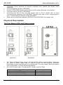
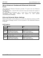
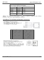
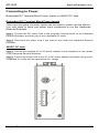
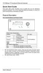
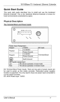
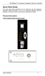
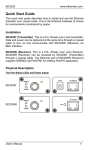
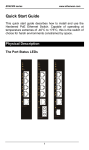
ED3538 www.etherwan.com Quick Start Guide This quick start guide describes how to install and use the Hardened Ethernet Extender. This is the Hardened Ethernet Extender of choice for harsh environments constrained by space. Installation ED3538T (Transmitter): This is a PoL (Power over Link) transmitter. Data and power can be delivered at the same time through one pair copper wire to turn on and communicate with ED3538R (Receiver) via RJ-11 phone jack or 2-pin Terminal Block interface. ED3538R (Receiver): This is a PoL (Power over Link) Receiver. ED3538R (Receiver) can be powered either by ED3538T (Transmitter) through one pair copper wire or power supply. The Ethernet port supports IEEE802.3at PoE/PSE for fulfilling PoE/PD application. <Warning> Removes the device power before installation. Removes the device power before any I/O and DIP switch configuration. Do not connect ED3538T and ED3538R to the same power source. Devices may be damaged due to power loop back through the PoL linked via copper wire. PoL (Power over Link) Mode Enable Installation Ensures all power sources are disconnected from ED3538T and ED3538R. Ensures ED3538T PoL (Power over Link) DIP switch is in On position (Up position). Sets ED3538T Type DIP switch to Perf (Performance, Up position) to acquire better Line Speed (but poor noise immunity). Or sets Type DIP switch of ED3538T to Std (Standard, Down position) to acquire standard Line Speed (but better noise immunity). Checks if ED3538R Mode is set to Rmt on DIP switch (Remote, Up position). Connects one end of the one pair copper wire to RJ-11 phone jack or 2-pin Terminal Block interface of the ED3538T and the other end to RJ-11 phone jack or 2-pin Terminal Block interface of the ED3538R. Connects power source to ED3538T. Data and power can be delivered from ED3538T, and at the same time through one pair copper wire to turn on and communicate with ED3538R. <Note> The equipment is designed for building installation and not intended to be connected to exposed (outside plant) networks including campus environment or equivalent. PoL (Power over Link) Mode Disable Installation For longer distance (e.g. over 1.4km) extension application, ED3538R may not be able to receive power from ED3538T. A separate power may be applied on ED3538R. Ensures all power sources are disconnected from ED3538T and ED3538R. Ensures ED3538T PoL (Power over Link) DIP switch is in Off position (Down position). Sets ED3538T Type DIP switch to Perf (Performance, Up position) to acquire better Line Speed (but poor noise immunity). Or sets Type DIP switch of ED3538T to Std User’s Manual 1 ED3538 www.etherwan.com (Standard, Down position) to acquire standard Line Speed (but better noise immunity). Connects power source to ED3538T. Checks if ED3538R Mode is set to Rmt on DIP switch (Remote, Up position). Connects power source to ED3538R. Connects one end of the one pair copper wire to RJ-11 phone jack or 2-pin Terminal Block interface of the ED3538T and the other end to RJ-11 phone jack or 2-pin Terminal Block interface of the ED3538R. Data can be transmitted between ED3538T and ED3538R via copper wire. Physical Description The Port Status LEDs and Power Inputs ED3538T ED3538R DC Terminal Block Power Inputs: 2.5A @ 48VDC (Peak current 3.26A). There are two pairs of power inputs can be used to power up this Ethernet Extender. Redundant power supplies function is supported. You only need to have one power input connected to run the Ethernet Extender. DC JACK Power input: 2.5A @ 48VDC (Peak current 3.26A). Power supply suggestion SDR-120-48 / DR-120-48 (120W 48VDC) SDR-240-48 (240W 48VDC) SDR-480-48 (480W 48VDC) User’s Manual 30 watts application For one pair For three pairs For seven pairs 2 ED3538 www.etherwan.com Power Input Assignment Power1 48VDC + T:46-57V / R:46-57V DC Power2 - Power Ground + T:46-57V / R:46-57V DC Power3 - Power Ground DC Jack Terminal Block Earth Ground DIP Switch ED3538T PoL Type Down Up Disable Power over Link Std (Standard) Standard line speed Better noise immunity Enable Power over Link Perf (Performance) Better line speed Poor noise immunity Loc (Local) Set ED3538R to Local Mode Std (Standard) Standard line speed Better noise immunity Rmt (Remote) Set ED3538R to Remote Mode Perf (Performance) Better line speed Poor noise immunity ED3538R Mode Type LEDs Power 1/2/3 PoL PoE Link Line Speed PSE Output State Steady Off Steady Off Steady Off Steady Fast Flashing Slow Flashing Off Indication Power received Power off Power Ethernet extension interface function is enabled No power is transmitted over Ethernet extension interface Powered device (PD) is connected Powered device (PD) is disconnected A valid Extender connection established Data transmission or receiving Extender port under negotiation mode Extender interface connection is not established Steady Displays the link speed in Mbps Steady All off PoE power can be transmitted for PD No PoE power can be transmitted for PD Steady A valid Ethernet connection established Flashing Data transmission or receiving Off Non-Ethernet connection is established Steady Link speed at 100Mbps Off Link speed at 10Mbps Green Yellow User’s Manual 3 ED3538 www.etherwan.com Power over Link (PoL) Enabled Distance Data Rate ED3538R PoE Output 300M 100Mbps 30.0W 400M 90Mbps 15.4W 600M 60Mbps 14.0W 800M 45Mbps 9.5W 1000M 35Mbps 7.0W 1200M 20Mbps 5.0W Power over Link (PoL) Disabled Power Supply Applied on ED3538R Distance Data Rate ED3538R PoE Output 1400M 15Mbps 30.0W 1600M 10Mbps 30.0W 1800M 3Mbps 30.0W Up to 2200M 1Mbps 30.0W <Note> The Reference Performance is tested on 24AWG Telephone wire (0.5mm diameter, 1-pair wire, Cable impedance: 100ohm). 10/100Base-TX and Ethernet Extender Connectors 10/100Base-TX Connection The following lists the pinouts of 10/100Base-TX RJ-45 port. Pin 1 2 3 4 5 6 7 8 User’s Manual Regular Port Output Transmit Data + Output Transmit Data Input Receive Data + Input Receive Data - PoE Port Output Transmit Data + Output Transmit Data Input Receive Data + Positive (VCC+) Positive (VCC+) Input Receive Data Negative (VCC-) Negative (VCC-) 4 ED3538 www.etherwan.com Ethernet Extender Connection The RJ-11 and Terminal Block port pinouts Pin 3: Tip, Pin 4: Ring. Use a telephone line to connect two RJ-11 or Terminal Block ports between two Hardened Ethernet Extenders. Functional Description Meets EN61000-6-2 & EN61000-6-4 EMC Generic Standard Immunity for industrial environment. Ethernet port: Supports IEEE802.3/802.3u/802.3x. Auto-negotiation: 10/100Mbps, full/half-duplex; Auto MDI/MDIX. Auto data rate negotiation for Ethernet extension interface. Six speeds with speed indicator LEDs on front panel of unit, up to 100Mbps @ about 300meters (984ft.), down to 1Mbps @ about 2,200meters (7,218ft.). Supports Power over Ethernet application up to 1,200meters (3,937ft.) for Max. 5 watts power consumed PoE powered devices. Power consumption: Enable Power over Link (PoL) function: Max. 65Watts Disable Power over Link (PoL) function: ED3538T: Max. 5W. ED3538R: Max. 35W with PoE output, Max. 5W without PoE output. Power Supply: Redundant T:46-57V / R:46-57V DC Terminal Block power inputs and 48VDC Latched DC JACK interface. Operating temperature range @ -40℃ to 75℃ (-40℉ to 167℉). Tested for functional operation @ -40℃ to 85℃ (-40℉ to 185℉). Supports Din-Rail or Panel Mounting installation. User’s Manual 5 ED3538 www.etherwan.com Preface This manual describes how to install and use the Hardened Ethernet Extender. The Hardened Ethernet Extender introduced here provides one channel for Ethernet over existing voice grade copper wire. The Hardened Ethernet Extender fully complies with IEEE802.3 10Base-T and IEEE802.3u 100Base-TX standards. In this manual, you will find: Product overview Features on the Hardened Ethernet Extender Illustrative LED functions Installation instructions Specifications User’s Manual 6 ED3538 www.etherwan.com Table of Contents Quick Start Guide ......................................................................... 1 Installation.................................................................................... 1 Physical Description .................................................................... 2 The Port Status LEDs and Power Inputs.................................... 2 10/100Base-TX and Ethernet Extender Connectors .................. 4 Functional Description................................................................. 5 Preface............................................................................................ 6 Table of Contents .......................................................................... 7 Introduction ................................................................................... 8 Product Overview......................................................................... 8 Product Features .......................................................................... 8 Packing List.................................................................................. 9 One-Channel Hardened Ethernet Extender ............................. 10 Ports ........................................................................................... 10 Ethernet Extender Mode Settings ............................................... 10 DIP Switch.................................................................................. 10 Front Panel & LEDs .................................................................. 11 LED Indicators......................................................................... 11 10/100Base-TX and Ethernet Extender Connectors ................ 12 Installation ................................................................................... 13 Selecting a Site for the Equipment.............................................. 13 DIN Rail Mounting ..................................................................... 13 Connecting to Power .................................................................. 15 Redundant DC Terminal Block Power Inputs ......................... 15 48VDC DC Jack ...................................................................... 15 Specifications ............................................................................... 17 User’s Manual 7 ED3538 www.etherwan.com Introduction The Hardened Ethernet Extender provides one channel for Ethernet over existing voice grade copper wire. This Hardened Ethernet Extender solution is perfectly fitted in the industrial applications or rugged environment. Product Overview ED3538T ED3538R Product Features Meets EN61000-6-2 & EN61000-6-4 EMC Generic Standard Immunity for industrial environment. Ethernet port: Supports IEEE802.3/802.3u/802.3x. Auto-negotiation: 10/100Mbps, full/half-duplex; Auto MDI/MDIX. Auto data rate negotiation for Ethernet extension interface. Six speeds with speed indicator LEDs on front panel of unit, up to 100Mbps @ about 300meters (984ft.), down to 1Mbps @ about 2,200meters (7,218ft.). User’s Manual 8 ED3538 www.etherwan.com Supports Power over Ethernet application up to 1,200meters (3,937ft.) for Max. 5 watts power consumed PoE powered devices. Power consumption: Enable Power over Link (PoL) function: Max. 65Watts Disable Power over Link (PoL) function: ED3538T: Max. 5W. ED3538R: Max. 35W with PoE output, Max. 5W without PoE output. Power Supply: Redundant T:46-57V / R:46-57V DC Terminal Block power inputs and 48VDC Latched DC JACK interface. Operating temperature range @ -40℃ to 75℃ (-40℉ to 167℉). Tested for functional operation @ -40℃ to 85℃ (-40℉ to 185℉). Supports Din-Rail or Panel Mounting installation. Packing List When you unpack this product package, you will find the items listed below. Please inspect the contents, and report any apparent damage or missing items immediately to our authorized reseller. The Hardened Ethernet Extender User’s Manual AC to DC Power Adaptor and Power Cable (optional) User’s Manual 9 ED3538 www.etherwan.com One-Channel Hardened Ethernet Extender Ports The Hardened Ethernet Extender provides TX ports and one Ethernet Extender port. For the TX ports, it uses RJ-45 connector and auto senses the speed of 10/100Mbps. For the Ethernet Extender port, it uses RJ-11 and Terminal Block connectors and auto senses the speed of Link (below 20)/20/40/60/80/100Mbps. Ethernet Extender Mode Settings Ethernet Extender mode settings are made very simple by means of a DIP (Dual Inline Package) switch on the top panel of the Hardened Ethernet Extender. DIP Switch DIP Down Switch ED3538T PoL Disable Power over Link Std (Standard) Type Standard line speed Better noise immunity ED3538R Loc (Local) Mode Set ED3538R to Local Mode Std (Standard) Type Standard line speed Better noise immunity User’s Manual Up Enable Power over Link Perf (Performance) Better line speed Poor noise immunity Rmt (Remote) Set ED3538R to Remote Mode Perf (Performance) Better line speed Poor noise immunity 10 ED3538 www.etherwan.com Front Panel & LEDs LED Indicators The LED indicators give you instant feedback on status of the Hardened Ethernet Extender: LEDs Power 1/2/3 State Steady Off Steady PoL Off PoE Link Line Speed PSE Output Steady Off Steady Fast Flashing Slow Flashing Off Indication Power received Power off Power Ethernet extension interface function is enabled No power is transmitted over Ethernet extension interface Powered device (PD) is connected Powered device (PD) is disconnected A valid Extender connection established Data transmission or receiving Extender port under negotiation mode Extender interface connection is not established Steady Displays the link speed in Mbps Steady All off PoE power can be transmitted for PD No PoE power can be transmitted for PD A valid Ethernet connection Steady established Flashing Data transmission or receiving Non-Ethernet connection is Off established Steady Link speed at 100Mbps Off Link speed at 10Mbps Green Yellow Power over Link (PoL) Enabled Distance Data Rate ED3538R PoE Output User’s Manual 300M 100Mbps 30.0W 400M 90Mbps 15.4W 600M 60Mbps 14.0W 800M 45Mbps 9.5W 1000M 35Mbps 7.0W 1200M 20Mbps 5.0W 11 ED3538 www.etherwan.com Power over Link (PoL) Disabled Power Supply Applied on ED3538R Distance Data Rate ED3538R PoE Output 1400M 15Mbps 30.0W 1600M 10Mbps 30.0W 1800M 3Mbps 30.0W Up to 2200M 1Mbps 30.0W <Note> The Reference Performance is tested on 24AWG Telephone wire (0.5mm diameter, 1-pair wire, Cable impedance: 100ohm). 10/100Base-TX and Ethernet Extender Connectors 10/100Base-TX Connection The following lists the pinouts of 10/100Base-TX RJ-45 port. Pin 1 2 3 4 5 6 7 8 Regular Port Output Transmit Data + Output Transmit Data Input Receive Data + Input Receive Data - PoE Port Output Transmit Data + Output Transmit Data Input Receive Data + Positive (VCC+) Positive (VCC+) Input Receive Data Negative (VCC-) Negative (VCC-) Ethernet Extender Connection The RJ-11 and Terminal Block port pinouts Pin 3: Tip, Pin 4: Ring. Use a telephone line to connect two RJ-11 or Terminal Block ports between two Hardened Ethernet Extenders. User’s Manual 12 ED3538 www.etherwan.com Installation This chapter gives step-by-step installation instructions for the Hardened Ethernet Extender. Selecting a Site for the Equipment As with any electric device, you should place the equipment where it will not be subjected to extreme temperatures, humidity, or electromagnetic interference. Specifically, the site you select should meet the following requirements: The Surrounding Air temperature should be between -40 to 75 degrees Celsius. The relative humidity should be less than 95 percent, non-condensing. Surrounding electrical devices should not exceed the electromagnetic field (RFC) standards. Make sure that the equipment receives adequate ventilation. Do not block the ventilation holes of the equipment. The power outlet should be within 1.8 meters of the product. DIN Rail Mounting Fix the DIN rail attachment plate to the back panel of the Hardened Ethernet Extender. Installation: Place the Hardened Ethernet Extender on the DIN rail from above using the slot. Push the front of the Hardened Ethernet Extender toward the mounting surface until it audibly snaps into place. Removal: Pull out the lower edge and then remove the Hardened Ethernet Extender from the DIN rail. User’s Manual 13 ED3538 User’s Manual www.etherwan.com 14 ED3538 www.etherwan.com Connecting to Power Redundant DC Terminal Block Power Inputs or 48VDC DC Jack: Redundant DC Terminal Block Power Inputs There are two pairs of power inputs can be used to power up this device. You only need to have one power input connected to run the Hardened Ethernet Extender. Step 1: Connect the DC power cord to the plug-able terminal block on the Hardened Ethernet Extender, and then plug it into a standard DC outlet. Step 2: Disconnect the power cord if you want to shut down the Hardened Ethernet Extender. 48VDC DC Jack Step 1: Connect the supplied AC to DC power adapter to the receptacle on the topside of the Hardened Ethernet Extender. Step 2: Connect the power cord to the AC to DC power adapter and attach the plug into a standard AC outlet with the appropriate AC voltage. User’s Manual 15 ED3538 www.etherwan.com Power Input Assignment Power1 48VDC + T:46-57V / R:46-57V DC Power2 - Power Ground + T:46-57V / R:46-57V DC Power3 - Power Ground DC Jack Terminal Block Earth Ground User’s Manual 16 ED3538 www.etherwan.com Specifications Applicable Standards IEEE802.3 10Base-T, IEEE802.3u 100Base-TX Fixed Ports 10/100Mbps Ethernet ports with RJ-45 connectors 1 x Ethernet Extender port with RJ-11 and Terminal Block connectors Speed 10Base-T 100Base-TX Ethernet Extender 10/20Mbps for half/full-duplex 100/200Mbps for half/full-duplex Link (Below 20), 20, 40, 60, 80, 100Mbps Switching Method Store-and-Forward Forwarding rate 14,880/148,810pps for 10/100Mbps Cable 10Base-T 100Base-TX Ethernet Extender LED Indicators 4-pair UTP/STP Cat. 3, 4, 5 up to 100m 4-pair UTP/STP Cat. 5 up to 100m Telephone wires Per Unit (3 LEDs)- Power1, Power2, Power3 Dimensions Weight Power Power Consumption User’s Manual ED3538TPoL; Line Speed (Mbps): Link, 20, 40, 60, 80, 100 ED3538RPoE; Line Speed (Mbps): Link, 20, 40, 60, 80, 100; PSE Output (Watts): 5, 15, 30 50mm (W) × 110mm (D) x 135mm (H) (1.97” (W) x 4.33” (D) x 5.31” (H)) 0.77Kg (1.7lbs.) Terminal Block: T:46-57V / R:46-57V DC DC Jack: 48VDC, External AC/DC required Terminal Block & DC Jack Power Inputs: 2.5A @ 48VDC (Peak current 3.26A) Enable PoL: Max. 65Watts Disable PoL: ED3538T: Max. 5W ED3538R: Max. 35W with PoE output Max. 5W without PoE output 17 ED3538 Operating Temperature www.etherwan.com -40℃ ~ 75℃ (-40℉ ~ 167℉) Tested for functional operation @ -40℃ ~ 85℃ (-40℉ ~ 185℉) Storage Temperature -40℃ ~ 85℃ (-40℉ ~ 185℉) Humidity 5 ~ 95%, non-condensing EMI FCC Part 15, Class A EN61000-6-4: EN55022, EN61000-3-2, EN61000-3-3 EN61000-6-2: EN61000-4-2 (ESD Standard) EN61000-4-3 (Radiated RFI Standards) EN61000-4-4 (Burst Standards) EN61000-4-5 (Surge Standards) EN61000-4-6 (Induced RFI Standards) EN61000-4-8 (Magnetic Field Standards) IEC60068-2-6 Fc (Vibration Resistance) IEC60068-2-27 Ea (Shock) IEC60068-2-32 Ed (Free Fall) EMS Environmental Test Compliance User’s Manual 18