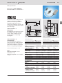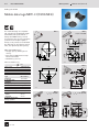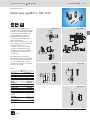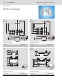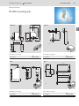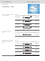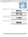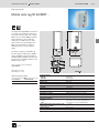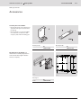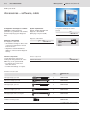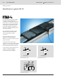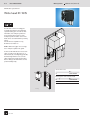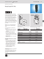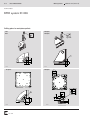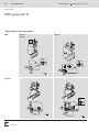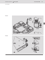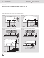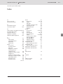
1
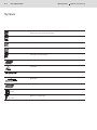
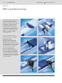
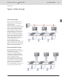
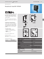
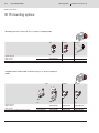
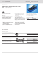
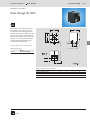
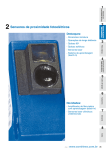
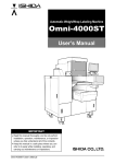
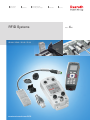
Electric Drives and Controls Hydraulics RFID Systems ID 200 / ID 40 / ID 15 / ID 10 www.boschrexroth.com/RFID Linear Motion and Assembly Technologies Pneumatics Service Version 4.0 0–2 RFID systems Bosch Rexroth AG Symbols Suitable for use in ESD sensitive areas. Please contact your Rexroth representative. Protection class [IP] Dynamic data transmission Working frequency 125 kHz Pneumatic connection required 4...6 bar PROFIBUS DP AS-interface ModbusTCP EtherNet/IP PROFINET Reference to technical data/dimensions 6‑2 Reference to another page 3‑3 3 842 541 004 (2012-12) 3 842 541 004 (2012-12) RFID systems Bosch Rexroth AG 1–1 RFID systems Table of Contents Introduction 1 RFID system ID 200 2 RFID system ID 40 3 RFID system ID 15 4 Identification system ID 10 5 Technical data 6 Overview of part numbers, Index 7 8 9 10 11 12 13 14 15 16 17 18 19 20 The data specified above only serve to describe the product. No statements concerning a certain condition or suitability for a certain application can be derived from our information. The information given does not release the user from the obligation of own judgment and verification. It must be remembered that our products are subject to a natural process of wear and aging. 1–2 RFID systems Bosch Rexroth AG RFID systems RFID in assembly technology Identification and data storage systems are used for controlling numerous production and transport systems in assembly technology. On the one hand, data related to objects is the basis for targeted control of process and processing steps and, on the other, is used for type or variant-dependent infeeding and outfeeding of workpiece pallets when manufacturing product variants on multi-branch flexible assembly systems. Two basic principles are used for dealing with workpiece-related data: ID 200 - VarioFlow ID 200 - TS 5 ID 200 - TS 2plus ID 40 - TS 2plus ID 15 - TS 2plus ID 10 - TS 2plus Central data storage Based on central collection of all workpiece-relevant data. Reliable identification of the workpiece at the processing station is required so that the appropriate data can be retrieved from the central data storage location. Decentralized data storage Based on mobile data tag systems, where the workpiece-relevant data is sent along directly with the workpiece (or on the workpiece pallet). Powerful read and write heads that can read out or modify the information needed at the processing stations. 3 842 541 004 (2012-12) 3 842 541 004 (2012-12) RFID systems Bosch Rexroth AG 1–3 RFID systems Types of data storage Central data storage 1 With central data storage, the data related to the process and product is centrally collected. Mobile data tags on the workpiece pallet, as well as the appropriate reading devices, ensure reliable identification of the workpieces at the processing stations. Using the workpiece ID, the appropriate data set is indexed to load the data into the PLC or cell control. The cell control unit reads the product type (variants, order or production lot) and the corresponding manufacturing status. This information is used to indicate whether any process steps are necessary and which ones. At the end, after finishing in the processing station, the information in the data set is supplemented. The data flow between the processing station and the host process requires a network. 2 3 4 5 6 7 8 9 10 11 12 Decentralized data storage 13 With decentralized data storage, the data related to the process and product accompanies the workpiece. To do this, the workpiece pallets are equipped with a mobile data tag with more storage capacity, which offers the option to read and write data. The data is always up-to-date at every processing station thanks to the read/ write heads that can read out and edit data at any time. The individual stations can thus carry out the production process independently; a network is not necessary for the workpiece data. 14 15 16 17 18 19 20 1–4 RFID systems Bosch Rexroth AG 3 842 541 004 (2012-12) RFID systems Main features System Central data storage Decentralized data storage PLC connection via Data Installation on workpiece pallet Maximum speed for dynamic reading ID 40 0 ++ – + – – – – – + + + – 30 1.28 MHz ID 15 ++ – + – – – – – – o + + + 20 125 kHz ID 10 0 + – – – – – – + + + + – 0 – (mm) ID 200 ++ ++ – + + + + + – + + + + 30 125 kHz 13.56 MHz 35 12 20 3 (°C) –25 to +85 0 to +70 –40 to +85 +5 to +60 10 billion 2 KB 10 billion 32 KB 100000 15 bits 10 million 2 bit/MDT AS-i PROFIBUS DP Modbus EtherNet/IP PROFINET TCP/IP Parallel Write Read Assembly module Integration (m/min) Frequencies Max. static reading distance Operating temperature Data tag Min. number of write cycles Max. storage size 3 842 541 004 (2012-12) RFID systems Bosch Rexroth AG 2–1 RFID system ID 200 RFID system ID 200 Operating principle 2-2 1 Communication module 2-4 2 Antenna 2-5 3 2-6 4 2-8 5 2-10 6 2-12 7 2-14 8 Mobile data tag Mounting kits Mounting options Accessories – cable Diagnostic devices 9 10 11 12 13 14 15 16 17 18 19 20 2–2 Bosch Rexroth AG RFID systems 3 842 541 004 (2012-12) RFID system ID 200 RFID system ID 200 125 kHz 13,56 MHz The RFID system ID 200 is a modular identification system developed for industrial use in production environments. The system consists of mobile data tags, antennas and communication modules. It is characterized by the robust and compact construction of its components, as well as by particularly interference-resistant and safe data transmission. ID 200 is ideal for applications with central or decentralized data storage. The mobile data tags with cost-effective EEPROM memory are very small and suitable for applications with low data volume. The design with FRAM memory is able to store larger data quantities decentrally and can be read/written almost an indefinite number of times. They are preferable for applications with short transmission times. Antennas are available in various construction designs and transmission frequencies. This allows the best design to be selected for each application and installation location. The communication modules connect the antennas and the master control system. They can control up to two antennas simultaneously, even with different frequencies. The interface to the control system can be either PROFIBUS DP or Ethernet. 00133431 3 842 541 004 (2012-12) RFID systems Bosch Rexroth AG 2–3 RFID system ID 200 1 MDT...H 2‑6, 2-7 2 3 2 4 MDT...L 1 3 2‑5 5 6 7 4 5 2‑4 8 6 9 10 11 12 13 00133483 1 Mobile data tags MDT...L for 125 kHz. 2 Mobile data tags MDT...H for 13.56 MHz 14 3 Flat antennas A...F for 125 kHz or 13.56 MHz. 4 Round antennas A...R for 125 kHz or 13.56 MHz 5 Communication module C-... for PROFIBUS or Ethernet. 6 Control system 15 16 17 18 19 20 2–4 RFID systems Bosch Rexroth AG 3 842 541 004 (2012-12) RFID system ID 200 Communication module ID 200/C-... 125 kHz 13,56 MHz IP 65 42 The communication module connects the antennas with the control system. There are plug-in connections for up to two antennas, which can be simultaneously active and are able to work with different frequencies. A digital sensor can optionally be connected at each antenna connection. Parameterization and diagnosis are performed via the integrated web server. 33 00133453 136,6 92 15 19 36 61,4 ID 200/C-PDP The connection to the control system is established via PROFIBUS-DPV0. The integrated web server can be reached via a separate RS-232 interface. 107 ID 200/C-ETH The connection to the control system is established via Ethernet. Ethernet protocols PROFINET/IO, Modbus/TCP and EtherNet/IP are available in addition to TCP/IP. An integrated switch allows cabling in line structure as well as the classical Ethernet star-form cabling. 00132000 Operating voltage Ripple Power consumption Status displays Connections Communication module ID 200/C-... ID 200/C-PDP ID 200/C-ETH No. 3 842 410 061 3 842 410 060 Protection class Housing material Ambient temperature Storage temperature Humidity Vibration resistance Shock and impact resistance Approvals Mass 20 to 30 VDC, PELV ≤ 10% Max. 1.5 A (incl. 2 antennas) 7 LEDs RS232 ID 200/C-PDP PROFIBUS-DPV0 PROFINET ID 200/C-ETH Ethernet/IP Modbus/TCP TCP/IP IP65 Aluminum, powder coated RAL 7035 –25 to +70°C –30 to +80°C Max. 96% 3.5 mm (10 to 55 Hz); 20 g (55 to 2000 Hz) 70 g/6 ms, 18 cycles EN 300330, ETS 300683, CE, FCC 0.5 kg 3 842 541 004 (2012-12) RFID systems Bosch Rexroth AG 2–5 RFID system ID 200 Antenna ID 200/A-... 125 kHz 13,56 MHz 00133438 2 4 27 Note: Mobile data tags MDT.../...H for 13.56 MHz F2 2-6 Mobile data tags MDT.../...L for 125 kHz F2 2-7 4,4 80 LED L 7 M12x1 8 00133480 9 Antenna ID 200/A-...F Antenna ID 200/A-...R No. ID 200/A-HF (13.56 MHz) 3 842 410 065 ID 200/A-LF (125 kHz) 3 842 410 176 No. ID 200/A-HR (13.56 MHz) 3 842 410 063 ID 200/A-LR (125 kHz) 3 842 410 177 Type Operating voltage (from communication module) Power consumption Status display Protection class Housing material ID 200/A-LR 5 6 6 14 24 28 20,8 66 50 4 55 26 00133481 Accessories: Mounting kits F2 2‑8 3 16 3,6 Antenna ID 200/A-...F (flat antenna) The flat design of the antenna is optimal for installation on the side of transfer systems. Other installation sites are possible with the corresponding mounting kits. Antenna ID 200/A-...R (round antenna) The round design of the antenna is particularly suited for reading data tags mounted on the bottom of workpiece pallets. Other installations are possible with the corresponding mounting kits. 1 16,4 7 12 The antennas enable reading from and writing to mobile data tags MDT...L (125 kHz, low frequency) or MDT...H (13.56 MHz, high frequency). The antennas are intended for operation with a communication module, which supplies them with voltage. M18x1 10 11 12 ID 200/A-LF ID 200/A-HR ID 200/A-HF 24 V 24 V 24 V 24 V 0.35 A LED yellow/green 0.35 A LED yellow/green 0.35 A LED yellow/green 0.35 A LED yellow/green IP67 IP67 IP67 IP67 15 ABS 16 PBT/ PBT/ ABS stainless steel stainless steel –25 to +70°C –25 to +70°C –25 to +70°C –40 to +85°C –40 to +85°C –40 to +85°C Max. 96% Max. 96% Max. 96% 1 mm (10 to 55 Hz); 5 g (10 to 2000 Hz) Ambient temperature Storage temperature Humidity Vibration resistance Shock and impact 30 g/11 ms, 18 cycles resistance 0.1 kg 0.1 kg Mass 125 kHz 125 kHz Transmission frequency Write/read distance 18 mm 18 mm – Static 16 mm – Dynamic (v = 20 m/min) 16 mm Min. distance between two antennas 30 mm 50 mm – Multiplex operation 290 mm – Simultaneous operation 180 mm –25 to +70°C –40 to +85°C Max. 96% 0.1 kg 13.56 MHz 0.1 kg 13.56 MHz 35 mm 30 mm 35 mm 30 mm 30 mm 80 mm 100 mm 150 mm 13 14 17 18 19 20 2–6 RFID systems Bosch Rexroth AG 3 842 541 004 (2012-12) RFID system ID 200 Mobile data tags MDT...H (13.56 MHz) IP 68 13,56 MHz 00133441 MDT 1 MDT 2 Iwt, bwt > 160 (PA) 32,5 5 10,7 8 9 24,5 10,5 20 2 MDTs with FRAM memory —— Storage capacity: 2000 byte user memory —— Each with an additional and unique 64 bit serial number —— Read/write cycles: 1010 2,5 4 2,8 2,8 14,3 2,8 14,8 11,5 00133503 00133523 22,7 The mobile data tags are compatible with international standard ISO 15693 (13.56 MHz) and operate without a battery with FRAM memory. Several housing types allow for many installation positions on the workpiece pallet or directly on the products to be identified. The data tags can be read from several sides, also dynamically while passing. 9 MDTs with FRAM memory No. 3 842 410 104 3 842 410 103 3 842 410 102 3 842 410 124 3 842 410 184 MDT 3 24 6 3,3 20 ,5 MDT.../2K-H 13.56 MHz ISO 15693 2000 bytes 8-byte block FRAM ≥ 10 billion Unlimited 35 mm 30 mm 6 26 00133502 33 00133500 MDT 4 Iwt, bwt > 160 (PE) 21433 MDT 6 Iwt, bwt = 160 (PA, PE) 21434 4 –25 to +85°C PA66 30 9,3 10,3 2,9 17 10 16 21441 6‑2 10,7 21442 24 8 5 25, 14 19,8 21,1 20 11,2 Type Frequency Conformity with standards Storage capacity Data access Memory type Number of write cycles Number of read cycles Transfer distance – Static – Dynamic Ambient temperature during operation Housing material 1,5 00133524 22,6 5 5 5 5 5 16 MDT 1/2K-H MDT 2/2K-H MDT 3/2K-H MDT 4/2K-H MDT 6/2K-H 00133501 3 842 541 004 (2012-12) RFID systems Bosch Rexroth AG 2–7 RFID system ID 200 Mobile data tag MDT...L (125 kHz) IP 68 00133442 ID 15 data tags from production date FD986 onward can be initialized with the aid of the DPS/L diagnostic set for use with ID 200. However, simultaneous operation on ID 15 and ID 200 is not possible. MDT 11/28-L MDT 21/28-L 7,6 6,5 7,6 18 6,5 4 9 3 4 13 13 3,3 8 15,5 6 5 5 5 5 5 9 10 MDT 22/28-L MDT 13/28-L 6‑4 MDT.../28-L 125 kHz – 5 bytes EEPROM ≥ 100,000 Unlimited 18 mm 16 mm –40 to +85°C PA66 11 12 13 No. 3 842 535 916 3 842 535 919 3 842 535 443 3 842 535 911 3 842 535 442 Type Frequency Conformity with standards Storage capacity Memory type Number of write cycles Number of read cycles Transfer distance – Static – Dynamic Ambient temperature during operation Housing material 7 8 MDT...L MDT 11/28-L MDT 21/28-L MDT 22/28-L MDT 13/28-L MDT 23/28-L 4 5 18 2,8 (2x) 1 2 7,6 6,5 2,5 The mobile data tag MDT.../28-L is located directly on the workpiece pallet and stores the identification assigned by the user during initialization. The compact MDT has a non-volatile EEPROM (battery buffers are not necessary) and a storage capacity of 5 bytes (useful data). MDT.../28-L can be read from all sides (front, left/right side, top and bottom) with unlimited frequency. In addition to numerous installation positions on the workpiece pallet, the data tag can also be seamlessly integrated in the workpiece pallet F2 4‑8, 4-9. 14 15 16 17 MDT 23/28-L 18 19 20 2–8 RFID systems Bosch Rexroth AG 3 842 541 004 (2012-12) RFID system ID 200 ID 200 mounting kits 00133437 100 56,4 72,4 108,5 23 30,5 5,5 40,4 TS 1 TS 2plus TS 4plus 66,9 81 34 21438 21437 ID 200/MS-1 mounting kit ID 200/MS-1 21436 No. 3 842 410 095 ID 200/MS-2 3 4 45 59 00133518 00133519 00133487 00133515 ID 200/MS-3 mounting kit ID 200 /MS-3 23,5 14,4 38,5 26,5 TS 2plus TS 4plus 71,4 38,5 34 21439 ID 200/MS-2 mounting kit No. 3 842 410 098 TS 4plus 85,4 15 3 15 3 81 20,8 81,4 TS 1 TS 2plus TS 4plus ID 200/MS-4 mounting kit No. 3 842 410 101 ID 200/MS-4 No. 3 842 410 100 RFID systems 3 842 541 004 (2012-12) Bosch Rexroth AG 2–9 RFID system ID 200 ID 200 mounting kits 00133436 TS 2plus VarioFlow 1 3 98,5 4 5 15 20,5 50 45 68 2 6 53 7 17 8 45 35,5 00133522 9 3 21435 21439 10 00133488 ID 200/MS-6 mounting kit ID 200/MS-5 mounting kit No. 3 842 410 096 ID 200/MS-5 ID 200/MS-6 TS 5 11 No. 3 842 410 097 12 13 TS 5 93 b = 455 b = 650+845 222,4 93 14 15 156 124 90 16 17 237 106 18 216,4 19 106 20 00133520 00133521 00133505 ID 200/MS-7 mounting kit ID 200/MS-7 00133506 ID 200/MS-8 mounting kit No. 3 842 545 144 ID 200/MS-8 No. 3 842 545 148 2–10 RFID systems Bosch Rexroth AG 3 842 541 004 (2012-12) RFID system ID 200 ID 200 mounting options TS 1 TS 2plus TS 2plus lwt, bwt > 160 (PA) TS 2plus lwt, bwt > 160 (PE) 13,56 MHz Mobile data tag MDT 1/2K-H MDT 2/2K-H MDT 3/2K-H MDT 4/2K-H MDT 6/2K-H Mounting kit for WT 5 Flat antenna mounting kit ID 200/MS-1 ID 200/MS-3 ID 200/MS-4 ID 200/MS-7 (Longitudinal conveyor) ID 200/MS-8 (Transverse conveyor) Flat antenna ID 200/A-HF Round antenna mounting kit ID 200/MS-6 Round antenna ID 200/A-HR 3 842 410 104 3 842 410 104 3 842 410 103 3 842 410 124 3 842 410 098 3 842 410 065 3 842 410 098 3 842 410 065 3 842 410 100 3 842 410 100 3 842 410 065 3 842 410 065 3 842 410 097 3 842 410 097 3 842 410 063 3 842 410 063 125 kHz Mobile data tag MDT 11/28-L MDT 13/28-L MDT 21/28-L MDT 22/28-L MDT 23/28-L Mounting kit for WT 5 Flat antenna mounting kit ID 200/MS-2 ID 200/MS-3 ID 200/MS-4 ID 200/MS-5 ID 200/MS-7 (Longitudinal conveyor) ID 200/MS-8 (Transverse conveyor) Flat antenna ID 200/A-LF 3 842 535 916 3 842 535 911 3 842 535 919 3 842 535 443 3 842 535 442 3 842 535 442 3 842 410 095 3 842 410 095 3 842 410 095 3 842 410 095 3 842 410 100 3 842 410 176 3 842 410 176 3 842 410 176 3 842 410 176 3 842 410 176 3 842 541 004 (2012-12) RFID systems Bosch Rexroth AG 2–11 RFID system ID 200 ID 200 mounting options 1 2 TS 2plus TS 4plus lwt, bwt = 160 (PA, PE) TS 5 VarioFlow 3 4 5 3 842 410 104 6 3 842 410 102 3 842 410 102 3 842 410 102 3 842 410 102 3 842 545 450 3 842 545 450 7 3 842 410 184 3 842 410 098 8 9 3 842 410 098 3 842 410 101 10 3 842 410 100 3 842 545 144 3 842 410 065 3 842 410 065 3 842 410 065 3 842 410 065 3 842 410 065 3 842 545 148 11 3 842 410 065 12 3 842 410 097 13 3 842 410 063 14 15 16 17 3 842 535 919 18 3 842 535 443 3 842 535 442 3 842 410 095 3 842 535 442 3 842 545 450 3 842 535 442 3 842 545 450 3 842 535 442 20 3 842 410 095 3 842 410 101 3 842 410 100 3 842 410 096 3 842 545 144 3 842 545 148 3 842 410 176 3 842 410 176 19 3 842 410 176 3 842 410 176 3 842 410 176 3 842 410 176 2–12 RFID systems Bosch Rexroth AG 3 842 541 004 (2012-12) RFID system ID 200 Accessories – cable 00133440 Connection cable between antenna and communication module. Antenna cable Socket Plug ID 200/K-ANT2-2M l (m) No. 2 3 842 410 108 5 3 842 410 109 2 3 842 410 110 5 3 842 410 111 l (m) No. 5 3 842 410 119 l (m) No. 5 3 842 410 114 10 3 842 410 115 20 3 842 410 116 5 3 842 410 117 00133489 straight angled ID 200/K-ANT2-5M 00133489 straight angled ID 200/K-ANT3-2M 00133490 angled angled ID 200/K-ANT3-5M 00133490 angled Power supply for communication module. angled Power supply cable ID 200/K-VCC-5M 00133493 Ethernet cable for connection between communication module and control system. Ethernet cable ID 200/K-ETH M12 - 5M 21446 ID 200/K-ETH M12 - 10M 21446 ID 200/K-ETH M12 - 20M 21447 ID 200/K-ETH RJ - 5M ID200_Ethernet 3 842 541 004 (2012-12) RFID systems Bosch Rexroth AG 2–13 RFID system ID 200 00133439 PROFIBUS cable for connection between communication module and control system. PROFIBUS cable Cable ID 200/K-PDP R l (m) No. 0.2 3 842 410 112 00133491 PROFIBUS cable with terminating resistor ID 200/K-PDP Y 0.2 3 842 410 113 00133492 Required accessories: null modem cable 2 3 4 PROFIBUS Y cable Diagnosis cable for PROFIBUS variants. For connection between communication module and PC. 1 5 6 7 Diagnostic cable l (m) No. 0.15 3 842 410 120 8 9 ID 200/K diag 00133494 10 11 Null modem cable for connection of the diagnostic cable to a PC for PROFIBUS variants. 12 Null modem cable ID 200/K-NMK 00133495 l (m) No. 13 2 3 842 410 129 14 15 16 17 18 19 20 2–14 RFID systems Bosch Rexroth AG 3 842 541 004 (2012-12) RFID system ID 200 Diagnostic devices 00133435 DPS/H diagnostic device The manual control unit can be used as a convenient mobile diagnostic device or for initial startup of the system. It can be used for data entry and to read out data for MDTs with 13.56 MHz. Manual control unit DPS/H DPS/H No. 3 842 410 066 Rechargeable battery DPS/H-ACC No. 3 842 410 164 Required accessories: USB communication and charge cable, rechargeable battery Optional accessories: recharging station 00133454 00133444 00133447 USB cable DPS/H-USB DPS/L diagnostic device Test and initial description of the mobile data tags MDT.../28-L (125 kHz) via a PC outside the system. Software functions: —— Reading the MDT.../28-L —— Writing the MDT.../28-L —— Import prepared lists (csv format) —— Writing the MDT.../28-L according to a list Scope of delivery: —— Manual antenna with data cable for connection to a USB port —— Software on CD-ROM Recharging station No. 3 842 410 165 DPS/H-CRG No. 3 842 410 166 Diagnostic set DPS/L DPS/L No. 3 842 406 959 00123856 3 842 541 004 (2012-12) RFID systems Bosch Rexroth AG 3–1 RFID system ID 40 RFID system ID 40 Operating principle 3-2 1 Mobile data tag 3-3 2 Read/write head 3-4 3 Accessories 3-5 4 5 6 7 8 9 10 11 12 13 14 15 16 17 18 19 20 3–2 RFID systems Bosch Rexroth AG 3 842 541 004 (2012-12) RFID system ID 40 Identification and data storage system ID 40 The ID 40 identification system enables a secure and fast provision of workpiece data on the workpiece pallet. There needs to be certain information available on each arriving part at every workstation, for example: —— Type of workpiece —— Production stage —— Next processing step —— Parameter settings These are particularly important if more than one product model is being processed on the same circuit. These data are stored by a stationary read/write head (SLK) 3‑4 on a mobile data tag (MDT) 3-3, which is directly located on the workpiece pallet (WT) and stays there throughout the entire assembly process. This decentralized data storage ensures short access times and optimum system availability. 00123943 An integrated delete function that only has to be triggered in the SLK makes it possible to empty the data storage without remaining near the SLK. The read/write head (SLK) offers a direct fieldbus connection, for the – PROFIBUS DP fieldbus system via M12 plug connectors. a = 2–10 mm Front transmission area The ID 40 is suitable for dynamic data transfer: When travelling past at a distance of "a" with a transport speed of up to 30 m/min the transfer capacity of 64 bytes is reached. a = 2–6 mm Side transmission area A user manual, current information and software can be downloaded at www.boschrexroth.com/RFID 3 842 541 004 (2012-12) RFID systems Bosch Rexroth AG 3–3 RFID system ID 40 Mobile data tag ID 40/MDT… IP 68 1,28 MHz 00123944 The mobile data tag (MDT) for the ID 40 is located on the workpiece pallet and saves the workpiece data. The compact MDT has a non-volatile RAM (no battery buffer required). It can be read and written up to 10 billion times on three sides (on the front, left and right). The MDT can be mounted in a variety of different positions on the workpiece pallet. 1 2 3 4 5 6 The memory capacity of the MDT can be either approx. 2 KB, approx. 8 KB or approx. 32 KB. The three-color LED on the MDT displays OK data transfers and transfer errors. The MDT complies to the IP68 protection class. 7 8 9 Scope of delivery: Incl. mounting kit 3 842 529 237. 10 11 Optional accessories: Assembly kits 3‑5 12 Mobile data tag ID 40/MDT… ID 40/MDT2K ID 40/MDT32K 6‑3 No. 3 842 406 150 3 842 406 170 Storage capacity - MDT2K - MDT32K Data retention time Data access Ambient temperature during operation Storage temperature Humidity Protection class Housing material Resistance to media Mass Transmission direction Read/write distance – Front – Side Permissible height offset between read/ write station and MDT Status displays Installation in metal 1904 bytes 30800 bytes >10 years (20 to 40°C) Byte-wise –25 to +70°C –25 to +85°C +5 to 95% IP68 Polyamide, PA6 Water, mineral oil; others on request 0.06 kg Front or left/right side 4 to 12 mm / 4 to 10 mm, static/dynamic 1 to 7 mm / 1 to 6 mm, static/dynamic +/- 5 mm LED, 3-color 10 mm free space required on all sides 13 14 15 16 17 18 19 20 3–4 RFID systems Bosch Rexroth AG 3 842 541 004 (2012-12) RFID system ID 40 Read/write head ID 40/SLK-… 00123945 The read/write head (ID 40/SLK-…) transfers workpiece data between the MDT and a bus master, which controls the workpiece pallets in the Rexroth transfer system. With the standard-mounting kit, the SLK is easy to install in the TS 1, TS 2plus and TS 4plus Rexroth transfer systems. Direct connection to the – PROFIBUS DP (ID 40/SLK-PDP) fieldbus system via M12 plug connectors. The antenna on the SLK can be swiveled to 90° and turned to 180°, which allows a variety of different installation positions. The semi-transparent antenna cover lights up when data is being transferred to the MDT. The 4-digit alphanumerical LED displays the current status of the field bus connection and communication with the MDT. The integrated serial RS232 interface enables parameterization and diagnosis, e.g. with a web browser and a PC notebook. The standard AS-i profile cable provides a user-friendly power supply (black). The SLK complies to protection class IP65. Scope of delivery: Incl. mounting kit 3 842 527 634. Read/write head ID 40/SLK-… ID 40/SLK–PDP No. 3 842 406 130 Operating voltage Ripple Power consumption Field bus connections Serial interface Status displays Protection class Ambient temperature Storage temperature Humidity Approvals Mass (incl. mounting plate) Max. write/read distance – Static – Dynamic (v = 20 m/min) Min. distance between two write/read heads Installation in metal 24 V –15 + 20% < 10% Max. 0.35 A Profibus DPV0 RS232 1 LED Alphanumeric display IP65 +5 to +55°C –20 to +85°C ≤ 96% EN 300330, ETS 300683, CE 0.4 kg 12 mm 10 mm 100 10 mm free space required 3 842 541 004 (2012-12) RFID systems Bosch Rexroth AG 3–5 RFID system ID 40 Accessories Assembly kit for ID 40/MDT... 1 —— Mounting kit (A) with reinforced design for applications with high mechanical load on the data tag. 2 —— Mounting kit (B) for use with ID 40/MDT as a replacement for ID 80/E on WT2 workpiece pallets with ID 80 drilling plan. 3 4 5 6 Mounting kit (A) 7 Mounting kit (B) No. 3 842 535 740 No. 3 842 532 630 8 9 Mounting kit for ID 40/SLK only vibration-free assembly. Application in environments with a higher vibration stress (on request). 10 11 12 100 13 14 15 72 00133499 00133498 16 17 18 Mounting kit ID 40 30 No. 3 842 538 784* * Availability and price upon request. 19 20 3–6 RFID systems Bosch Rexroth AG 3 842 541 004 (2012-12) RFID system ID 40 Accessories – software, cable 00123857 Configuration and diagnosis software package for setting the device parameters (e. g. field bus node number) and for interpreting system diagnostic data. System requirements Win NT 4.0/Win 2000/Win XP diagnostic cable RS232 (M12 plug on 9-pin. D-SUB) Configuration and diagnosis software package No. 3 842 406 119 Diagnostic cable RS232 Diagnostic cable RS232 The diagnostic cable aids: —— efficient data exchange to direct serial connection at workstations via web browser function. —— adjustment of the ID 40/SLK bus address to read out internal diagnosis memory Function components contain all the basic functions for reading and writing data blocks on the MDT. They can be parameterized. —— For Siemens S7 controls from CPU 315 onward —— For Rexroth IndraLogic on request l (m) 2 No. 3 842 406 117 Function components No. 3 842 406 190 Siemens S7 controls Field bus connection cable l (m) PROFIBUS DP*) No. M12 plug straight, open end 3 3 842 410 030 M12 socket straight, open end 3 3 842 410 031 M12 plug angled, open end 3 3 842 410 032 M12 socket angled, open end 3 3 842 410 033 M12 plug angled, M12 socket angled 3 3 842 410 034 Field bus terminating resistor — 3 842 406 156 *) No GND at pin 5, shield on housing 3 842 541 004 (2012-12) RFID systems Bosch Rexroth AG 4–1 RFID system ID 15 RFID system ID 15 Operating principle 4-2 1 Read/write head 4-3 2 Mobile data tag 4-4 3 Diagnostic set 4-5 4 Mounting kits 4-6 5 Protective cover 4-7 6 Mounting options 4-8 7 4-10 8 Addressing device and AS-i accessories 9 10 11 12 13 14 15 16 17 18 19 20 4–2 RFID systems Bosch Rexroth AG 3 842 541 004 (2012-12) RFID system ID 15 Identification system ID 15 The ID15 identification system enables the reliable and fast identification of workpieces. The data tags can not only be mounted on or below the workpiece pallet, they can also be fully integrated in the workpiece pallet. Short access times with a high level of immunity to interference and high availability are the main system features. The read/write head (SLK) provides a direct connection to the actuator sensor level with AS-i via M12 connectors. The ID 15 enables dynamic data transmission: when passing at a distance of "a" and at a transport speed of up to 20 m/min. A separate antenna with a USB connection, in conjunction with the ID15 diagnosis software, makes it possible to easily and quickly initialize the data tag. 00123835 A user manual, current information and software can be downloaded at www.boschrexroth.com/RFID a = 0–20 mm Front transmission area a = 0–10 mm Top transmission range a = 0–20 mm Side transmission area 3 842 541 004 (2012-12) RFID systems Bosch Rexroth AG 4–3 RFID system ID 15 Read/write head ID 15/SLK IP 67 00123847 The read/write head (ID 15/SLK) is used to transfer workpiece data between the MDT.../28-L and an AS-i bus master for controlling workpiece pallets in Rexroth transfer systems. 55 1 41 LED 2 17 24 The SLK can be easily installed in the Rexroth TS 1, TS 2plus, TS 4plus transfer system as well as the VarioFlow chain conveyor system using standard mounting kits. Direct connection to AS-i via M12 connectors (can be swiveled by 270°). Three LEDs indicate —— Operational readiness (green) —— Presence of a data tag in the field (yellow) —— Malfunction (red) 3,7 4 4,2 5 6 4,5 17 M12x1 7 8 4 Max. 15 bit user data can be written on or read from an MDT.../28‑L using ID 15/ SLK. 69 55 3 536035-12.eps 9 10 a a a a 11 a 12 Scope of delivery: Read/write head Required accessories: Mounting kit corresponding to application case F2 4-6 Read/write head ID 15/SLK ID 15/SLK No. 3 842 406 960 13 14 a a 100 mm Operating voltage (via AS-i power supply) Power consumption Field bus connections Status displays Protection class Housing material Ambient temperature Storage temperature Humidity Vibration resistance EN 60068-2-6 Shock and impact resistance EN 60068-2-29 Shock and impact resistance EN 60068-2-27 Approvals Mass Max. write/read distance – Static – Dynamic (v = 20 m/min) Min. distance between two write/read heads a > 100 mm 536035-15.eps 26.5 to 31.6 V Max. 0.1 A AS-i, profile 7.4 3 LEDs IP67 PA –20 to +60°C –25 to +80°C 95% 20 g (10 to 2000 Hz) 40 g/6 ms 50 g/11 ms EN 300330, EN 61326, CE, FCC 0.1 kg 20 mm 15 mm 400 mm (read and write) 200 mm (read only) 15 16 17 18 19 20 4–4 RFID systems Bosch Rexroth AG 3 842 541 004 (2012-12) RFID system ID 15 Mobile data tag MDT...L (125 kHz) IP 68 00123839 ID 15 data tags from production date FD986 onward can be initialized with the aid of the DPS/L diagnostic set for use with ID 200. However, simultaneous operation on ID 15 and ID 200 is not possible. MDT 11/28-L MDT 21/28-L 7,6 7,6 6,5 7,6 18 6,5 4 9 6,5 4 13 13 MDT 22/28-L 2,8 (2x) 3,3 8 15,5 18 2,5 The mobile data tag MDT.../28-L is located directly on the workpiece pallet and stores the identification assigned by the user during initialization. The compact MDT has a non-volatile EEPROM (battery buffers are not necessary) and a storage capacity of 5 bytes (useful data). MDT.../28-L can be read from all sides (front, left/right side, top and bottom) with unlimited frequency. In addition to numerous installation positions on the workpiece pallet, the data tag can also be seamlessly integrated in the workpiece pallet F2 4‑8, 4-9. MDT 13/28-L MDT...L MDT 11/28-L MDT 21/28-L MDT 22/28-L MDT 13/28-L MDT 23/28-L 5 5 5 5 5 No. 3 842 535 916 3 842 535 919 3 842 535 443 3 842 535 911 3 842 535 442 Type Frequency Conformity with standards Storage capacity Memory type Number of write cycles Number of read cycles Transfer distance – Static – Dynamic Ambient temperature during operation Housing material 6‑4 MDT.../28-L 125 kHz – 5 bytes EEPROM ≥ 100,000 Unlimited 18 mm 16 mm –40 to +85°C PA66 MDT 23/28-L 3 842 541 004 (2012-12) RFID systems Bosch Rexroth AG 4–5 RFID system ID 15 Diagnostic set DPS/L Application: Test and initial description of the mobile data tags MDT.../28-L (125 kHz) via a PC outside the system. 1 2 3 Software functions: —— Reading the MDT.../28-L —— Writing the MDT.../28-L —— Import prepared lists (csv format) —— Writing the MDT.../28-L according to a list 4 5 6 Scope of delivery: —— Manual antenna with data cable for connection to a USB port —— Software on CD-ROM 7 8 9 10 00123856 12 Diagnostic set DPS/L DPS/L 11 No. 3 842 406 959 13 14 15 16 17 18 19 20 4–6 RFID systems Bosch Rexroth AG 3 842 541 004 (2012-12) RFID system ID 15 Mounting kits for read/write head, ID 15/SLK 5 15 9,5 6 45 5 17 40,5 2,5 26 26 14 17 4,8 (2x) 6,6 66 0,5 4,8 (2x) 4,3 (2x) 20 35 2,5 6,6 12,5 24 12,5 18 26,5 33,5 26 47 4,5 10,5 Ø 4,2 (8x) 17 12,512,5 00134926 00134927 00133525 00133526 Mounting kit ID 15/MS-1 Mounting kit ID 15/MS-2 No. 3 842 535 920 ID 15/MS-1 41,5 21,5 37 24,5 24,5 4,8 (2x) 40 64 2,5 37 00134930 00134925 Mounting kit ID 15/MS-5 ID 15/MS-5 No. 3 842 535 918 4,3 (2x) 17 12 15 6,6 12 ID 15/MS-2 No. 3 842 535 917 3 842 541 004 (2012-12) RFID systems Bosch Rexroth AG 4–7 RFID system ID 15 Protective cover for ID 15/SLK Protective cover for ID 15/SLK 1 11 23,5 2 3 4 5 83 ID 15/SLK 11 No. 3 842 537 885 6 7 00130030 00133508 8 9 10 11 12 13 14 15 16 17 18 19 20 4–8 RFID systems Bosch Rexroth AG 3 842 541 004 (2012-12) RFID system ID 15 ID 15 mounting options Mounting to the top of a TS 1, TS 2plus or TS 4plus workpiece pallet TS 1 TS 2plus TS 4plus No. No. No. 3 842 535 919 3 842 535 920 3 842 535 919 3 842 535 920 TS 2plus TS 4plus No. No. 3 842 535 442 3 842 535 442 3 842 535 442 3 842 535 920 3 842 535 920 3 842 535 920 00134939 Mobile data tag MDT 11/28-L MDT 21/28-L Mounting kit for read/write head ID 15/MS-1 3 842 535 916 3 842 535 920 Integration in the frame module on the TS 1, TS 2plus or TS 4plus workpiece pallets TS1 No. Mobile data tag MDT 23/28-L MDT 13/28-L Mounting kit for read/write head ID 15/MS-1 3 842 535 911 3 842 535 920 3 842 541 004 (2012-12) RFID systems Bosch Rexroth AG 4–9 RFID system ID 15 Mounting to the bottom of a TS2plus workpiece pallet 1 2 3 TS 2plus 4 5 6 7 No. Mobile data tag MDT 22/28-L Mounting kit for read/write head ID 15/MS-2 3 842 535 443 3 842 535 917 8 9 10 11 Integration in the VarioFlow workpiece pallet 12 13 VarioFlow 14 15 16 17 Mobile data tag MDT 23/28-L Mounting kit for read/write head ID 15/MS-5 No. 18 3 842 535 442 3 842 535 918 19 20 4–10 RFID systems Bosch Rexroth AG 3 842 541 004 (2012-12) RFID system ID 15 Addressing device DPS/AS-i and AS-i accessories 00123942 Addressing device AS-i Application: The sturdy and handy addressing and diagnosis tool for initial operation, maintenance and service of AS-i systems provides the following: Functions: —— Reads out slave addresses 0 to 31, A, B without scrolling with a clear and complete LCD display —— Reads out slave IO and ID codes (including extended ID codes 1 and 2) —— Standard addressing mode, and extended addressing mode from AS-i version 2.1. —— Programming of ID code1 —— Slave function test, also for analog slaves with profile 7.1 to 7.4 —— Recognition of all system components —— Memory, diagnosis and PC gateway functions —— Data transmission, data management and documentation of system parameters with optional software —— Connection via M12 plug (A-coded) —— Infrared interface Scope of delivery: AS-i- addressing and testing appliance DPS/AS-i with batteries (4 x 1.5 V Mignon (AA) LR6). DPS/AS-i addressing device DPS/AS-i No. 3 842 406 173 AS-i accessories AS-i branch terminal to connect M12 plugs to an AS-i signal cable No. 3 842 406 176 AS-i branch terminal Connection cables M12 plug straight, M12 socket straight l (m) 0.5 1.0 M12 plug straight, M12 socket angled 0.5 No. 3 842 406 193 3 842 406 194 No. 3 842 406 166 1.0 3 842 406 171 3 842 541 004 (2012-12) RFID systems Bosch Rexroth AG 5–1 Identification system ID 10 Identification system ID 10 Operating principle 5-2 1 Data storage 5-3 2 Write head 5-4 3 Read head 5-5 4 5 6 7 8 9 10 11 12 13 14 15 16 17 18 19 20 5–2 RFID systems Bosch Rexroth AG 3 842 541 004 (2012-12) Identification system ID 10 Identification and data storage system ID 10 In the ID 10 identification and data storage system, encoding is carried out mechanically with encoding pins in the ID 10/D data storage. The ID 10/D data storage is carried on the workpiece pallet during the assembly process. 2 information bits can be encoded per data storage. Data storage units can be positioned adjacently to deal with larger quantities of data. The ID 10/S write head sets the encoding pins; the ID 10/L read head ascertains their position using proximity switches. The information obtained is passed on to a governing control unit or compared with preset required values in the read head. 00123937 C A B A B C Data storage ID 10/D on the workpiece pallet Read head ID 10/L Write head ID 10/S 3 842 541 004 (2012-12) RFID systems Bosch Rexroth AG 5–3 Identification system ID 10 Data storage ID 10/D 00123938 The ID 10/D carries information about the workpiece; several ID 10/Ds can be attached onto the workpiece pallet. Every ID 10/D has 4 encoding pins; they are coupled in pairs (1 and 2; 3 and 4). When an encoding pin is pushed in, the other pin of the pair is pushed forward automatically. Reading and writing is carried out on the same side. 1 2 3 4 5 Scope of delivery: incl. mounting material 6 Data storage ID 10/D 7 ID 10/D Nr. 10 3 842 508 038 8 9 10 11 12 Memory capacity and space required Data storage ID 10/D quantity Memory capacity in bits Number of possible codes Space required on the workpiece pallet (mm) 1 2 22 = 4 32 x 27 2 4 24 = 16 64 x 27 3 6 26 = 64 96 x 27 4 8 28 = 256 128 x 27 13 14 15 16 17 18 19 20 6‑6 5–4 RFID systems Bosch Rexroth AG 3 842 541 004 (2012-12) Identification system ID 10 Write head ID 10/S 00123939 The ID 10/S sets the encoding pins in the ID 10/D with four pneumatically operated setting pins. In order to write information, the workpiece pallet has to be stopped. The presence of the workpiece pallet in relation to the write head can be ascertained with a proximity switch. One ID 10/S is required for every ID 10/D to be written on. Note: If WT travel "gaps" are too large, use a workpiece pallet inner guide. To write to ID 10/D that are next to each other, you will receive kits with 1 to 4 write heads (A), including fixing plate (B) and fastening elements. You can also order single write heads and mounting kits for writing to ID 10/D which are not positioned adjacently. ID 10/S write head A B No. 3 842 168 610 A Mounting kit for n ID 10/S write heads B B 000012846.eps 6‑7 n 1 2 No. 3 842 525 241 3 842 525 242 3 842 541 004 (2012-12) RFID systems Bosch Rexroth AG 5–5 Identification system ID 10 Read head ID 10/L 00123940 Four proximity switches in the ID 10/L recognize the position of the encoding pins in the ID 10/D. The signals read are either transmitted directly to a control unit, which takes over the evaluation, or they are compared to preset information in the read head. The result of this comparison will be issued at an output of the ID 10/LA read head. Light-emitting diodes on the back of the housing permit a visual check of information which has been read. 1 1 An ID 10/L is required for every ID 10/D to be read from. The ID 10/LA read head is used once in each read station. Additional ID 10/LB read heads follow directly after the ID 10/LA. 6‑8 3 4 2 A 4 3 4 5 6 7 00116571.eps 8 Read head ID 10/L Two read head designs are currently available: —— ID 10/LA: Recognizes the workpiece pallet in the read position as well as the ID 10/D coding; outputs the signals for coding, "WT in position", and comparison results (yes/no). —— ID 10/LB: Recognizes the ID 10/D coding and outputs the signals. Forwards the internal comparison result to the ID 10/LA. 2 3 2 Note: In case of unwanted guide play with the WT use a workpiece pallet guide. The following types of operation are supported: —— Read code: Recognizes the ID 10/D coding and forwards the signal to a control unit. —— Compare code: Recognizes the ID 10/D coding and compares it with a preset code; the results of the comparison (yes/no) are then supplied in signal format. —— Both types of operation can be used simultaneously. 1 1x ID 10/LA 1x ID 10/LB ID 10/LA ID 10/LB Mounting kit for n ID 10/L... read heads No. 3 842 174 350 3 842 174 360 n 1 2 No. 3 842 525 261 3 842 525 262 9 10 11 Type Operating voltage Ripple Power consumption Parallel interface Status displays Protection class Housing material Ambient temperature Storage temperature Mass Max. write/read distance – Static – Dynamic (v = 20 m/min) ID 10/LA 10 to 30 V ≤ 5% Max. 0.65 A 6 outputs 3 LEDs IP67 Crastin +5 to +40°C –25 to +70°C 0.2 kg ID 10/LB 10 to 30 V ≤ 5% Max. 0.45 A 4 outputs 2 LEDs IP67 Crastin +5 to +40°C –25 to +70°C 0.2 kg 2.5 mm – 2.5 mm – 12 13 14 15 16 17 18 19 20 5–6 Bosch Rexroth AG Identification system ID 10 RFID systems 3 842 541 004 (2012-12) 3 842 541 004 (2012-12) RFID systems Bosch Rexroth AG 6–1 Technical data Technical data RFID system ID 200 6-2 1 RFID system ID 40 6-3 2 RFID system ID 15 6-4 3 Identification system ID 10 6-6 4 5 6 7 8 9 10 11 12 13 14 15 16 17 18 19 20 6–2 RFID systems Bosch Rexroth AG 3 842 541 004 (2012-12) Technical data RFID system ID 200 Drilling plans for workpiece pallets TS 1 WT1 TS 2plus TS 4plus PH SW4 M D = 5Nm 12 7,7 M3 7,7 12 00134931 00134932 TS 4plus TS 4plus 110 105 2,5 36 8 M3 15 12 24 12 26 15 00134933 00134934 2‑6 3 842 541 004 (2012-12) RFID systems Bosch Rexroth AG 6–3 Technical data RFID system ID 40 Drilling plans for workpiece pallets TS 1 1 TS 2plus 2 3 4 5 6 7 8 9 10 11 12 TS 4plus 13 14 15 16 17 18 19 20 3‑3 6–4 Bosch Rexroth AG RFID systems Technical data RFID system ID 15 Drilling plans for workpiece pallets TS 1 WT 1/K WT 1/S TS 2plus 2‑7, 4-4 WT 1/P 3 842 541 004 (2012-12) 3 842 541 004 (2012-12) RFID systems Bosch Rexroth AG 6–5 Technical data 1 TS 2plus 2 3 4 SW4 3 M 18,3 M D = 5Nm 5 6 7 8 21,2 9 10 11 12 13 TS 4plus 14 15 16 536035-35.eps 17 18 19 20 6–6 RFID systems Bosch Rexroth AG 3 842 541 004 (2012-12) Technical data Identification and data storage system ID 10 Drilling plans for TS 2plus and TS 4plus workpiece pallets TS 2plus Milling plan for TS 2plus WP aluminum carrier plate TS 2plus 5‑3 TS 4plus Milling plan for TS 4plus WP aluminum carrier plate TS 4plus 3 842 541 004 (2012-12) RFID systems Bosch Rexroth AG 6–7 Technical data Write head ID 10/S 1 2 3 4 5 6 p = 4-6 bar 7 8 Steckfix 4x1 9 10 11 Read head ID 10/L 12 13 14 15 16 17 18 19 20 5‑4, 5-5 7–0 RFID systems Bosch Rexroth AG 3 842 541 004 (2012-12) Overview of part numbers, Index Overview of part numbers Part number 3 842 168 610 3 842 174 350 3 842 174 360 3 842 406 117 3 842 406 119 3 842 406 130 3 842 406 140 3 842 406 141 3 842 406 142 3 842 406 143 3 842 406 145 3 842 406 150 3 842 406 154 3 842 406 156 3 842 406 160 3 842 406 166 3 842 406 170 3 842 406 171 3 842 406 173 3 842 406 176 3 842 406 190 3 842 406 191 3 842 406 193 3 842 406 194 3 842 406 959 3 842 406 960 3 842 409 904 3 842 410 030 3 842 410 031 3 842 410 032 3 842 410 033 3 842 410 034 3 842 410 060 3 842 410 061 3 842 410 062 3 842 410 063 3 842 410 064 3 842 410 065 3 842 410 066 3 842 410 095 3 842 410 096 3 842 410 097 3 842 410 098 3 842 410 100 3 842 410 101 Page 5-4 5-5 5-5 3-6 3-6 3-4 3-4 3-6 3-6 3-6 3-6 3-3 3-6 3-6 3-3 4-10 3-3 4-10 4-10 4-10 3-6 3-6 4-10 4-10 2-14, 4-5 4-3 3-6 3-6 3-6 3-6 3-6 3-6 2-4 2-4 2-5 2-5, 2-10 2-5, 2-10, 2-11 2-5, 2-10, 2-11 2-14 2-8, 2-10, 2-11 2-9, 2-11 2-9, 2-10 2-8, 2-10, 2-11 2-8, 2-10, 2-11 2-8, 2-11 Part number 3 842 410 102 3 842 410 103 3 842 410 104 3 842 410 105 3 842 410 106 3 842 410 107 3 842 410 108 3 842 410 109 3 842 410 110 3 842 410 111 3 842 410 112 3 842 410 113 3 842 410 114 3 842 410 115 3 842 410 116 3 842 410 117 3 842 410 118 3 842 410 119 3 842 410 120 3 842 410 129 3 842 410 164 3 842 410 165 3 842 410 166 3 842 508 038 3 842 525 241 3 842 525 242 3 842 525 245 3 842 525 246 3 842 525 249 3 842 525 250 3 842 525 253 3 842 525 254 3 842 525 261 3 842 525 262 3 842 527 634 3 842 529 237 3 842 532 630 3 842 535 442 3 842 535 443 3 842 535 740 3 842 535 911 3 842 535 916 3 842 535 917 Page 2-6, 2-11 2-6, 2-10 2-6, 2-10, 2-11 2-6, 2-11 2-6, 2-10 2-6, 2-10, 2-11 2-12 2-12 2-12 2-12 2-13 2-13 2-12 2-12 2-12 2-12 2-12 2-12 2-13 2-13 2-14 2-14 2-14 5-3 5-4 5-4 5-4 5-4 5-4 5-4 5-5 5-5 5-5 5-5 3-4 3-3 3-3 2-7, 2-10, 2-11, 4-4, 4-8, 4-9 2-7, 2-10, 2-11, 4-4, 4-9 3-3 2-7, 2-10, 4-4, 4-8 2-7, 2-10, 4-4, 4-8 4-6, 4-9 Part number 3 842 535 918 3 842 535 919 3 842 535 920 3 842 537 885 3 842 537 887 3 842 538 784 3 842 545 144 3 842 545 148 3 842 545 450 Page 4-6, 4-9 2-7, 2-10, 2-11, 4-4, 4-8 4-6, 4-8 4-7 3-5 3-5 2-9, 2-11 2-9, 2-11 2-11 3 842 541 004 (2012-12) RFID systems Bosch Rexroth AG 7–1 Overview of part numbers, Index Index A AS-i accessories AS-i branch terminal 4-10 4-10 C Central data storage Connection cables 1-3 4-10 D Data storage in assembly technology1-2 Decentral data storage 1-3 Diagnostic devices 2-14 4-5 Diagnostic set DPS/L DPS/AS-i addressing device 4-10 I 5-1 ID 10 5-3 Data storage 5-2 Operating principle 5-5 Read head 5-4 Write head ID 15 4-1 Accessories4-10 4-8 Assembly options 4-4 Data tags 4-5 Diagnostic set DPS/L Fastening sets for 4-6 read/write head 4-8 Integration in frame module Integration in 4-9 VarioFlow workpiece pallets Mounting on workpiece pallets 4-8 4-2 Operating principle 4-7 Protective cover 4-3 Read/write head 4-6, 4-7 ID 40 3-1 Accessories 3-5, 3-6 Cables3-6 Data tags 3-3 Field bus connection cable 3-6 Operating principle 3-2 Read/write head 3-4 Software3-6 ID 200 2-1 Accessories 2-12, 2-13 Antenna2-5 2-8, 2-9 Assembly kits 2-10 Assembly options Cables 2-12, 2-13 Communication module 2-4 2-6 Data tags MDT...H 2-7 Data tags MDT...L 2-14 Diagnostic devices 2-2 Operating principle Identification and 5-2 data storage system ID 10 Identification and 3-2 data storage system ID 40 Identification system ID 15 4-2 Identification system ID 200 2-2 M Main features 1-4 S Symbols0-2 T Table of contents Technical data 1-1 6-1 1 2 3 4 5 6 7 8 9 10 11 12 13 14 15 16 17 18 19 20 Bosch Rexroth AG Postfach 30 02 07 70442 Stuttgart, Germany Tel.+49 711 811-30698 Fax+49 711 811-30364 www.boschrexroth.com Find your local contact person here: www.boschrexroth.com/contact Subject to technical modifications © Bosch Rexroth AG 2012 Printed in Germany 3 842 541 004 (2012-12) EN • DC-IA/MKT