1
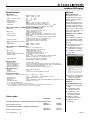
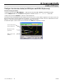
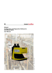
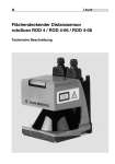
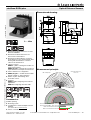
rotoScan ROD4 plus
Optical Distance Sensors
en 04-2010/05 50108253
Dimensioned drawing
0 … 65m
24 V
We reserve the right to make changes • DS_ROD4plus_en.fm
DC
z Measurement data transmission via Fast
Ethernet 100MBit/s
z Measurement data transmission via
RS 232/422 serial interface
z Measurement data reduction, measurement data processing, measurement data
filtering and determination of extreme
values in the interface box
z 2 device versions
ROD4-5… plus: scanning rate of 50Hz, for
object measurement
ROD4(-08) plus: scanning rate of 25Hz, for
object detection and object measurement
z Service interface for configuration
z ROD4(-08) plus: 7 storable and reversible
detection fields for object detection
z ROD4-…8 plus with heating, dustinsensitive version.
z Software
RODplussoft: Configuring measurement
applications
RODsoft: Configuring detection fields
C
UL
Measurement principle
190° working range
528 measurement sectors,
0.36° each
US
LISTED
IEC 60947...
IEC 60947...
IP 65
Accessories:
(available separately)
z Mounting system
z Configuration software RODplussoft and
RODsoft
(free download from www.leuze.de)
Measurement range ROD4(-50) plus: max. 65m
Measurement range ROD4-…8 plus: max. 25m
Radius of far detection field: max. 50m
Radius of near detection field: max. 30m
z Various connection cables
Leuze electronic GmbH + Co. KG
[email protected] • www.leuze.com
In der Braike 1 D-73277 Owen Tel. +49 (0) 7021 573-0
rotoScan ROD4 plus ... - 04
rotoScan ROD4 plus
Specifications
Notices
Approved purpose:
The distance sensors are
optical electronic sensors for
optical, contactless detection of objects.
This product may only be
used by qualified personnel
and must only be used for
the approved purpose. This
sensor is not a safety sensor
and is not to be used for the
protection of persons.
Optical data
Measurement range
Radius of detection field1)
Angular range
Angular resolution
Scanning rate
Transmitter
ROD4(-50) plus: 0 … 65m
ROD4-…8 plus: 0 ... 25m
near:
0 … 30m
far:
0 … 50m
max. 190°
0.36°
ROD4-5… plus: 50 scans/s or 20ms/scan
ROD4(-08) plus: 25 scans/s or 40ms/scan
infrared laser diode, wavelength = 905nm, Pmax = 15W,
pulse duration: 3ns, average output power: 12μW
Object measurement - ROD4(-08) plus and ROD4-5… plus
Reflectivity
from min. 1.8% (matte black)
ROD4-…8 plus from 6% (dark grey)
Object size
> 20mm at distance of 4m
> 100mm at distance of 15m
Response time
ROD4-5… plus: at least 20ms (corresponds to 1 scan)
ROD4(-08) plus: at least 40ms (corresponds to 1 scan)
Switching inputs
4x +24VDC
(FPS1 … 4 at Y1 for switching between detection fields)
additional restart input at Y1 and interface box
Switching outputs
4x PNP transistor outputs 24V/250mA
(Alarm, Warn, Near field 1, Near field 2)
Measurement value resolution per 5mm
sector
Repeatability2)
ROD4(-50) plus: ± 15mm
ROD4-…8 plus: ± 20mm
"RODplussoft" configuration software
The configuration software
runs under Windows 2000/
XP and offers the following
features:
z Configuration of Ethernet
and serial interface
z Configuration of up to 12
measurement segments
z Visualization of measurement values
Object detection - ROD4(-08) plus
Reflectivity
Object size
Response time
Number of detection field pairs
Switching inputs
Switching outputs
from min. 1.8% (matte black)
ROD4-08 plus from 6% (dark grey)
> 20mm at distance of 4m
> 100mm at distance of 15m
at least 40ms (corresponds to 1 scan)
7 (selectable via switching inputs)
4x +24VDC
(FPS1 … 4 at Y1 for switching between detection fields)
additional restart input at Y1 and interface box
4x PNP transistor outputs 24V/250mA
(Alarm, Warn, Near field 1, Near field 2)
AC
A
+24VDC +20% / -30%
fuse 2.5A (4A with heating) semi time-lag in the switch cabinet
approx. 1A (use power supply with 2.5A), approx. 4A with heating
< 75W at 24V including the outputs
overvoltage protection with protected limit stop
Mechanical data
Housing
Weight
Connection type
C
C
B
C
Electrical data
Voltage supply 3)
Overcurrent protection
Current consumption
Power consumption
Overvoltage protection
C
B
diecast aluminum, plastic
2.3kg
4 connectors (can be plugged from above)
Environmental data
Ambient temp. (operation/storage) -0°C … +50°C/-20°C … +50°C
-20°C … +50°C/-20°C … +50°C (ROD4-…8 plus)
VDE safety class
III, protective extra-low voltage
Protection class
IP 65
Laser class
1 (acc. to EN 60825-1 and 21 CFR 1040.10 with Laser Notice No. 50)
Standards applied
IEC 60947-5-2, UL 508
1) only applies for ROD4(-08) plus
2) 10 … 90% diffuse reflection, at operating range of 4m
3) Protective Extra Low Voltage (PELV) - protective extra-low voltage with reliable disconnection.
For UL applications: only for use in class 2 circuits according to NEC.
Order guide
Designation
For object detection / object measurement, scanning rate 25scans/s
ROD4 plus
With heating/dust-insensitive
ROD4-08 plus
Part No.
of the data transmission in the
A Configuration
"Configuration" tab
Definition
of
measurement
segments in the
B "Toolbox"
Graphical display of the measurement values
C of the measurement segments in various
colors
z Transfer of measurement
values in XY coordinates
or polar coordinates.
Configuration software
"RODsoft"
(for ROD4(-08) plus only)
z Definition of the detection
fields
z Configuration of the
scanner parameters
z Visualization of the
detection fields and
measurement values
z Display of status/
diagnostic information
z Support of various
languages
50106481
50106480
For object measurement, scanning rate 50scans/s
With heating/dust-insensitive
rotoScan ROD4 plus ... - 04
ROD4-50 plus
ROD4-58 plus
50113226
50113225
2010/05
rotoScan ROD4 plus
Optical Distance Sensors
Electrical connection - Assignment connector
Y1 Logic
PIN
A
C
E
G
J
L
M
N
O
P
R
S
T
U
Function
+UB
GND_IN
FPS1
FPS2
FPS3
FPS4
Restart_IN
Near field 1
Near field 2
Alarm
Warn
NC
NC
NC
Y2 Ethernet
Y3 Service
Y4 RS 232/422
PIN
1
2
3
4
PIN
1
2
3
4
5
PIN
1
2
3
4
5
6
7
8
Function
Tx+
Rx+
TxRx-
Function
NC
TxD
GND
RxD
NC
Function
TX+ / TxD
TxRxRx+ / RxD
GND/shield
RS 422 detection
NC
NC
Installing the software RODplussoft
The RODplussoft configuration software is used for configuring the interfaces and the measurement functions of the
ROD4… plus.
The RODplussoft configuration software can be found on the supplied CD. To install, follow the instructions in the respective
readme files, which can likewise be found on the supplied CD.
You can also download the respective, latest version of RODplussoft from www.leuze.com:
Download -> Detect -> Measuring sensors.
Unzip the ZIP file supplied into a suitable folder on your hard disk.
ª Start the installation by double-clicking on the setup.exe file.
ª Follow the instructions of the installation routine.
Notice!
Before installing RODplussoft, ensure that Microsoft® .NET Framework 2.0 SP1 or later is installed on your
computer.
Install the RODsoft software (for ROD4 plus and ROD4-08 plus only)
You have to install the RODsoft software only if you wish to create detection fields for optical distance sensors of type ROD4 plus
or ROD4-08 plus.
Notice!
With ROD4-5… plus sensors, status and diagnostic information can be called up using RODsoft.
The RODsoft configuration software can be found on the supplied CD. To install, follow the instructions in the respective readme
files, which can likewise be found on the supplied CD.
You can also download the respective, latest version of RODsoft from www.leuze.com:
Download -> Detect -> Measuring sensors.
Unzip the ZIP file supplied into a suitable folder on your hard disk.
ª Start the installation by double-clicking on the setup.exe file.
ª Follow the instructions of the installation routine.
Leuze electronic GmbH + Co. KG
[email protected] • www.leuze.com
In der Braike 1 D-73277 Owen Tel. +49 (0) 7021 573-0
rotoScan ROD4 plus ... - 04
rotoScan ROD4 plus
Establish connection to PC
The ROD4… plus is configured via a PC using the RODplussoft program, before it is integrated into the process control.
In order to be able to establish a TCP communication with the PC, the IP address of your PC and the IP address of the
ROD4… plus must lie in the same address range. The ROD4… plus has no built-in DHCP client, so that you need to set the
address manually. This is done the easiest way via the PC.
The ROD4… plus is set ex works as follows:
IP address:
192.168.060.003
Subnet mask:
255.255.255.0
Notice!
If you are using a desktop firewall, please ensure that the control can communicate with the ROD4… plus via
the Ethernet interface on ports 9008 and using TCP. Furthermore, the firewall must allow ICMP echo messages
to pass through for the connection test (ping).
If the PC is usually connected to a network using DHCP address allocation, the easiest way to access the ROD4… plus is by
applying an alternative configuration in the TCP/IP settings of the PC and connecting the ROD4… plus directly to the PC.
According to the default setting of 255.255.255.0 for the subnet mask, the IP address of the PC must lie then in the range
192.168.060.0 to 192.168.060.255 (e.g., 192.168.060.110, but not 192.168.060.003!), so that ROD4… plus and PC can communicate with each other. If ROD4… plus and PC have the same IP address, they cannot communicate with each other.
Configuring the IP address for a PC
ª Log in to your PC as an administrator.
ª Using Start->System control go to the Network connections
(Windows XP) menu or to the Network center and release
center (Windows Vista) menu.
ª There select the LAN connection and bring up the associated
Features page by right clicking with the mouse.
ª Select the Internet protocol (TCP/IP) (by scrolling down, if
necessary) and click on Properties.
ª In the Internet protocol (TCP/IP) Properties window select
the Alternate configuration tab.
ª Set the IP address of the PC in the address range of the
ROD4… plus.
Attention: Not the same as for the ROD4… plus!
ª Set the Subnet mask of the PC to the same value as the one for the
ROD4… plus .
ª Close the configuration dialog by confirming all windows using OK.
ª Connect the Y2 interface of the ROD4… plus directly to the LAN port
of your PC. Use a KB ET-…-SA-RJ45 cable for the connection.
rotoScan ROD4 plus ... - 04
2010/05
rotoScan ROD4 plus
Optical Distance Sensors
Commissioning
ª Switch on the supply voltage of the ROD4… plus.
ª Start the software RODplussoft.
The PC first tries to establish via Ethernet a network connection via the automatic configuration. This takes a few seconds, after
which the alternate configuration, which you just set, is activated. The PC can then communicate via Ethernet with the
ROD4… plus.
Further information about configuring the ROD4… plus using RODplussoft software can be found in the Technical Description
and Software and Protocol Description.
For the commissioning and integration of the sensor in the process control the following steps are necessary:
1. Configure the ROD4… plus - see chapter 6 of the Technical Description.
2. Configure, if necessary, detection fields with the RODsoft configuration software (Configuration –> Start RODsoft…
menu item) (for ROD4 plus and ROD4-08 plus only!). See Configuring detection fields section.
3. Program process control.
or
4. Connect the switching inputs and outputs accordingly - see chapter 5 of the Technical Description.
5. Adapt the IP configuration of the ROD4… plus such that it can communicate with the process control. This occurs in
ROD-plussoft in the Communication tab. Here you can change the network address and the corresponding net mask,
via which the ROD4… plus communicates with the process control.
6. Save the changed settings in the ROD4… plus using the Configuration -> Transmit to ROD4plus menu item.
7. Connect ROD4… plus to process control via the Ethernet interface Y2.
Leuze electronic GmbH + Co. KG
[email protected] • www.leuze.com
In der Braike 1 D-73277 Owen Tel. +49 (0) 7021 573-0
rotoScan ROD4 plus ... - 04
rotoScan ROD4 plus
Configure the detection fields (for ROD4 plus and ROD4-08 plus only)
Commissioning procedure:
ª Connect the PC via the KB-ROD4plus… cable at the connection Y3 - Service to the ROD4(-08) plus.
ª From RODplussoft start the RODsoft configuration software via the Start RODsoft… menu item.
ª Enter the password "ROD4LE" in the level "Authorized User".
The detection field can be displayed under "Display measurement contour". Under "ROD4 configuration" the response times, the
detection field switches and other parameters are defined. To configure the detection fields, select the "Define detection areas"
field. Error codes and other information are contained in the ROD4 system data.
A detailed description can be found in the user manual for the RODsoft configuration software.
Current measurement
values (yellow line)
Far detection field
(green line)
Near detection field
(red line)
rotoScan ROD4 plus ... - 04
2010/05