1
IFC PAL User Manual
Printing History
Edition 1
October 2003
Software Version 2.5.0
The PAL System may be operated with another level of firmware. Details of the current level are given with
the leaflet “Firmware Overview” which is placed in the front of this binder.
CTC Analytics AG reserves the right to make improvements and/or changes to the
product described at any time without notice.
CTC Analytics AG makes no warranty of any kind with regards to this product, including
but not limited to, the implied warranties or merchantability and suitability for a particular
purpose.
In no case shall CTC Analytics AG be liable for any coincidence ore consequential
damages in connection with or arising from the use of this document.
© 2003 CTC Analytics AG. All rights reserved. Neither this publication nor any part of
this publication may be copied, photocopied, reproduced, translated or reduced to any
electronic medium or machine readable form without the prior written permission of
CTC Analytics AG, except as allowed under the copyright laws.
CTC Analytics AG acknowledges all trade names and trademarks used as the property of
their respective owners.
1
IFC PAL User Manual
Safety Information
Declaration of Conformity
See Declaration of Conformity sheet enclosed with the instrument
General Considerations
Changes or modifications to this unit not expressly approved by the party responsible
for compliance could void the user’s authority to operate the equipment.
The user shall be made aware that if the equipment is used in a manner not specified
by the manufacturer, the protection provided by the equipment my be impaired.
When you use the PAL System, follow the generally accepted procedures for quality
control and methods development.
When you use the PAL System in the field of chromatographic analysis and you
observe a change in the retention of a particular compound, in the resolution between
two compounds, or in peak shape, immediately determine the reason for the changes.
Until you determine the cause of a change, do not rely on the separation results.
2
IFC PAL User Manual
Electrical Hazards
Every analytical instrument has specific hazards, so be sure to read and comply with the
following precautions. They will help ensure the safe, long-term use of your PAL System.
The Installation Category (Over voltage Category) for this instrument is Level II.
The Level II Category pertains to equipment that receives its electrical power from the
local level, such as an electrical wall outlet.
Only use fuses of the type and current rating specified. Do not use repaired fuses and
do not short-circuit the fuse holder.
The supplied power cord must be inserted into a power outlet with a protective earth
contact (ground). When using an extension cord, make sure that the cord also has an
earth contact.
Do not change the external or internal grounding connections. Tampering with or
disconnecting these connections could endanger you and/or damage the PAL System.
The instrument is properly grounded in accordance with these regulations when shipped.
You do not need to make any changes to the electrical connections or the instrument's
chassis to ensure safe operation.
The combination of a PAL System with a LC/MS System does require the safety measure
as described by the LC/MS System manufacturer. Detailed instructions for the safety
grounding on the LC/MS system are outlined in the corresponding operating/installation
manual.
CTC Analytics recommends to use a grounding cable connected on one side at the
Injection Valve, Loop or any other suitable direct metallic contact and the other side at
an appropriate grounding point at the LC/MS System. This supplementary grounding
measure will support the safety strategy of the LC/MS System manufacturer.
3
IFC PAL User Manual
Do not turn the instrument on if you suspect that it has incurred any kind of electrical
damage. Instead disconnect the power cord and contact a CTC Analytics representative
for a product evaluation. Do not attempt to use the instrument until it has been
evaluated. Electrical damage may have occurred if the PAL System shows visible signs of
damage, exposure to any liquids or has been transported under severe stress.
Damage can also result if the instrument is stored for prolonged periods under
unfavorable conditions (e.g. subjected to heat, water, etc.).
In any case disconnect the power cord(s) from the power supply or from the different
power supplies if optional devices are installed before attempting any type of
maintenance.
Capacitors inside the instrument may still be charged even if the instrument is turned off.
To avoid damaging electrical parts, do not disconnect an electrical assembly while
power is applied to the PAL system. Once the power is turned off, wait approximately
30 seconds before you disconnect an assembly.
The instrument includes a number of integrated circuits. These circuits may be damaged
if exposed to excessive line voltage fluctuations and/or power surges.
4
IFC PAL User Manual
Never try to repair or replace any components of the instrument that is not described in
this manual without the assistance of a CTC Analytics representative.
There are no operator-serviceable or replaceable parts inside the power supply(ies) or in
the PAL System. If a power supply is not functioning, contact a CTC Analytics
representative.
The power supply for the PAL Instrument has the symbols I/0 on the label for the power
switch to switch ON/OFF.
I = Power ON
0 = Power OFF
If the basic PAL System is installed, than a single power supply is installed only. Turning
OFF the power supply or pulling this single power cord in an emergency case will stop
the complete PAL System.
It is important that the power supply (ies) are in a location where the power ON and OFF
switch is accessible and easy to operate, and where it is possible to unplug the AC power
cord from the power supply/wall outlet in case of emergency.
5
IFC PAL User Manual
Other Hazards
To avoid injury during PAL System operation, keep your hands away from the syringe.
Do not operate the PAL System without the safety shield. The safety shield must be
installed for safe operation.
To avoid injury, observe safe laboratory practice when you handle solvents, change
tubing, or operate the PAL System. Know the physical and chemical properties of the
solvents you use. See the Material Safety Sheets from the manufacturer for the solvents
in use.
Use caution when working with any polymer tubing under pressure:
• Always wear eye protection when near pressurized polymer tubing.
• Do not use polymer tubing that has been severely stressed or kinked.
• Do not use polymer tubing, in particular not PEEK or Tefzel tubing, with
Tetrahydrofuran (THF), Dimethylsulfoxid (DMSO), chlorinated organic solvents,
concentrated mineral acids, such as Nitric, Phosphoric or Sulfuric acids, or any related
compounds to above listings.
6
IFC PAL User Manual
Lithium battery
An onboard lithium battery buffers the electronic memories, when the instrument is
turned off. Replace it only with the same or equivalent type recommended by the
equipment manufacturer.
Battery: Panasonic VL 2330, soldered directly on the electronic board.
Discharged lithium batteries shall be disposed off locally according to national waste
disposal regulations for batteries.
There are no operator-serviceable parts on the electronic boards.
If an electronic board fails, contact a CTC Analytics representative.
7
IFC PAL User Manual
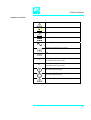
Commonly Used Symbols
Caution or refer to User Manual
Caution, Risk of Needle-Stick Puncture
Caution, Hot Surface or High Temperature
Direct Current
Alternating Current
Protective Conductor Terminal, Ground
Fuse
1
Electrical Power ON.
Used with Main PAL Power Supply.
0
Electrical Power OFF.
Used with Main PAL Power Supply.
Electrical Power ON for Only Part of the System.
Used with Optional Device(s)
Electrical Power OFF for Only Part of the System.
Used with Optional Device(s)
Caution, Risk of Electrical shock (high voltage)
8
IFC PAL User Manual
HTS PAL Operating Manual
General Information
.
Printing History
Safety Information
Tables of Content
1
2
9
A. IFC PAL Operating Instructions
15
1.
1.1
1.2
1.3
1.4
Using the Control Terminal
Menu Screens
Function Keys
ESCape and STOP Keys
Scroll Knob and ENTER Button
16
17
17
17
17
2.
2.1
2.2
2.3
Methods
Creating Methods
Edit / View Methods
Delete Methods
18
18
19
19
3.
3.1
3.2
3.3
Job and Job Queue
Building and Starting a Job Queue
Aborting a Job Queue
Restarting an Aborted Job Queue
20
20
21
21
4.
4.1
4.2
4.3
4.4
4.5
Utility Functions
Syringe
Tray
Injector
Wash Station
Dilutor (Side-port Syringe for Collector Side)
22
22
23
23
24
24
B. IFC PAL Description and Installation
26
5. General System Overview
5.1 IFC Pal used for Analytical Flow Rate Range
5.1.1 Specifications
5.2 IFC Pal used for Preparative Flow Rate Range
5.2.1 Specifications
5.3 Electrical Specifications
5.4 Physical Specifications
5.5 Operating and Environmental Requirements
26
26
27
28
27
30
33
33
6. Installation
6.1 IFC PAL Analytical Version
6.1.1 Unpacking the Components
6.1.2 Assembling
6.1.3 Electrical Connections
34
34
34
34
43
9
IFC PAL User Manual
6.2 IFC PAL Preparative Version
6.2.1 Unpacking the Components
6.2.2 Assembling
44
44
44
7. IFC PAL Object Positions
7.1 Defining Object Reference Positions
7.2 Description of Object Reference Positions
48
48
50
8.
8.1
8.2
8.3
8.4
8.5
8.6
Syringes
Selecting Syringes
Syringe Priming
Installing a Syringe for the IFC PAL Injector Side
Removing a Syringe
Installing a Syringe for the IFC PAL Collector Side
Removing a Syringe
53
53
55
55
57
58
61
9.
9.1
9.2
9.3
Injection Valve
Injection Valve Flow Path
Valve Needle Guide and Needle Seal
Injection Valve Needle Penetration
62
63
65
67
10. Interfacing the IFC PAL to other Devices
10.1 Synchronization and Output Signals
68
68
11. PAL Loader Program
11.1 Backing up the PAL Control Program
11.2 Reloading a Backup
69
69
70
12. Troubleshooting
71
13. Replacing Parts
13.1 MOTIO Board
13.2 Control Board
13.3 CPU Board
13.4 Injection Valve / Valve Rotor
73
73
74
75
76
14. Maintaining the PAL System
14.1 General Maintenace
14.2 Maintaining Sideport Syringe
80
80
81
10
IFC PAL User Manual
Appendices
58
A
Definition of Terms
58
B
Conventions of Naming
59
C
HTS PAL Injection Cycle
60
D
Software Flow Chart
63
E
External Connectors
65
11
IFC PAL User Manual
List of Figures
Figure 1
Figure 2
Figure 3
Figure 4
Figure 5
Figure 6
Figure 7
Figure 8
Figure 9
Figure 10
Figure 11
Figure 12
Figure 13
Figure 14
Figure 15
Figure 16
Figure 17
Figure 18
Figure 19
Figure 20
Figure 21
Figure 22
Figure 23
Figure 24
Figure 25
Figure 26
Figure 27
Figure 28
Figure 29
Figure 30
Figure 31
Figure 32
Figure 33
Figure 34
Figure 35
Figure 36
PAL Control Terminal and Conventions
Accessing a Method Screen
Example Job Queue Screen
IFG PAL- Major System Components for Analytical Version
IFG PAL- Major System Components for Preparative Version
Attachment of Mounting Claws
Attaching the PAL Injection Unit
Connecting the Injection Unit Flat Cable
Inserting the Injection Unit Mounting Torx Screws
IFC PAL with Injection Unit and Standalone Supports
Installing Keypad Terminal
Installing the Injection Valve Drive
Installing the Fast Wash Station
Fast Wash Station Assembly
Electrical Connection Fast Wash Station
Installing a Microplate Stack
Installing a Trayholder
IFC PAL Support Leg Transport Lock
IFC PAL Straining of Support legs
IFC PAL Assembling Tray Pan and X-/Y-Axis
IFC Assembly Front View
IFC PAL Assembling as an Example Configuration
Object Reference Position
Menu Screen Object Trayholder
Trayholder Reference Position
Stack Reference Position
Fast Wash Station Reference Positions
LC Valve and Waste Reference Position
Follower Pin for Slider Assembly, Preparative Version
Waste Position for Slider Assembly, Preparative Version
Syringe and Syringe Adapter
Installing and Removing a Syringe from the IFC PAL Injector Side
Attaching the Transfer Tubing Kit
Installing the Sideport Syringe from the IFC PAL Collector Side
Installing the Sideport Syringe Plunger Holder
Installing the Sideport Syringe Adapter
16
17
20
26
28
35
35
36
37
37
38
39
40
40
41
42
42
45
45
46
47
47
48
49
50
50
51
51
52
52
55
56
58
59
60
61
12
IFC PAL User Manual
Figure 37
Figure 38
Figure 39
Figure 40
Figure 41
Figure 42
Figure 43
Figure 44
Figure 45
Figure 46
Figure 47
Figure 48
Figure 49
Figure 50
LC Injection Valve Flow Path, Cheminert Valve
LC Injection Valve Flow Path, Valve Type-W
Valve Needle Guide and Seal
Menu Screen Valve Needle Penetration Depth
PAL Loader Menu Screen
PAL Loader Backup Target Memory
Replacing MOTIO Board
Replacing Control Board
Replacing CPU Board
Replacing Injection Valve, Cheminert Type
Replacing Valve Rotor, Cheminert Type
Replacing Injection Valve, Type W
Replacing Valve Rotor, Type W
Exchanging the Sideport Syringe
63
64
65
67
69
69
73
74
75
76
77
78
79
81
13
IFC PAL User Manual
How to Use this Manual
The manual is divided into three major sections
IFC PAL Operating Instructions Section A
IFC PAL Description and Installation Section B
Appendices
The "IFC PAL Operating instructions" in Section A are intended for infrequent PAL users
or new users that are experienced in using automated systems to perform existing
analytical methods.
note !
The IFC PAL must be installed and set up properly before the Operating Instructions
in Section A can be used.
Users who are installing a IFC PAL system, IFC PAL accessories or who need to make
adjustments to an installed system should consult "IFC PAL Description and Installation"
in Section B.
The Appendices provide useful information such as the Software Flow Chart, Definition of
Terms or the IFC PAL Accessories guide.
14
IFC PAL User Manual
A. IFC PAL Operating Instructions
The IFC PAL has to operated by a dedicated software, example IFC PAL Software provided
by CTC Analytics . The IFC PAL can also be integrated in other manufacturer software.
The IFC PAL can not be operated as a standalone unit.
All functions shown and explained in this Chapter A, “IFC Operating Instructions” have to
be considered as an instruction to install, trouble shoot or how to change a syringe as an
example.
The general functions of the Control Terminal are exactly the same as described for other
PAL Systems.
If the customer wishes to use the Injector side of the IFC PAL system to inject an
analytical samples, than all functions like the Method, Job or Job Queue are relevant.
15
IFC PAL User Manual
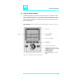
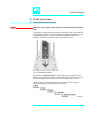
1. Using the Control Terminal
The following procedures present the key steps required to set up and process multiple
groups of samples with the IFC PAL. It is intended to provide an overview for new users
and a reminder for infrequent users. The IFC PAL and all accessories should be installed
and Objects defined correctly. A Syringe of the type called for in any Method to be used
should also be installed.
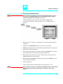
Figure 1 illustrates the PAL Control Terminal and the conventions used to enter, edit, and
view information.
Figure 1. PAL Control Terminal and Conventions
16
IFC PAL User Manual
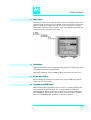
1.1. Menu Screens
Different menu screens are displayed depending on the HTS PAL operating state and the
particular function being accessed by the operator. All menu screens have the same basic
format. The menu title is displayed at the top of the screen. A list of items is displayed
below the title. The date and time or a status is shown in the highlighted area above the
Function key labels on the bottom of the screen.
Figure 2. Accessing a Method Screen
1.2 Function Keys
Options for a particular menu are assigned to the corresponding function keys (F1, F2, F3
and F4) directly below each function key label.
Pressing the function key defined as Home will always return to the Job Queue menu.
1.3 ESCape and STOP Keys
Press the ESCape key to return to the previous menu. Press the STOP key to abort the
current Cycle, Job, or Job Queue.
1.4 Scroll Knob and ENTER Button
Rotate the outer knob to scroll through items in a menu list. To select a highlighted item
press the central knob (ENTER button). Then use the outer knob to scroll through
available options for that item or to change a numeric value. Then press the inner knob
again to ENTER the displayed option. The inner knob is also used for other operations
that require an ENTER operation to continue or complete an operation.
17
IFC PAL User Manual
2. Methods
2.1 Creating Methods
Methods can be defined by the user and assigned names up to eight characters in length.
Methods can be created, copied, edited, and viewed from the Method menu. Methods
can be viewed but not edited from the Job menu.
Methods are created by either copying an existing Method or creating a new Method.
1
To copy a Method, complete the following sequence:
2
You will be prompted to enter a name for the new Method.
Use the scroll knob and the left-right arrow function keys (F2 and F3) to select among
alphanumeric characters and spaces. Press the ENTER function key (F4) to accept the
name.
1
To create a new Method, complete the following steps:
2
Assign and enter a new Method name as above.
After a copy of the Method has been created, the Method parameters will be displayed
and can be edited. The Cycle and Syringe entries cannot be changed.
3
If the Method is new (i.e. added), select and enter a Cycle that is appropriate for the
application.
4
Select the specific Syringe to be used by the Method.
note !
Once a Method has been created and saved, the Cycle and Syringe can not be
changed. To use a different Cycle or Syringe, a new Method must be created.
5
note !
Assign Parameter values according to the application requirements. Consult Appendix D
"HTS PAL LC-Inj Cycle Parameter" for details of the specific items.
The IFC can be used to inject an analytical sample, no fraction collector mode.
Therefore the “HTS PAL Cycle” has to be used.
18
IFC PAL User Manual
2.2 Edit / View Methods
Method parameters (excluding Cycle and Syringe) can be viewed and changed from the
Method menu as follows:
1
2
Scroll to and select the Parameter to be changed. Assign the new value and press the
ENTER key.
3
Exit from Parameter List by pressing either the Home function key (F4) to return to the
top-level Job Queue menu or the ESCape key to return to the previous menu.
4
Method contents may be viewed from the Job Queue displays by selecting the desired
Job, pressing ENTER, and the View Method function key.
2.3 Delete Methods
Methods can be deleted from the Method menu. Methods in use by an active Job cannot
be deleted. Complete the following menu selections to delete a Method.
19
IFC PAL User Manual
3. Job and Job Queue
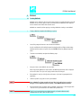
3.1. Building and Starting a Job Queue
1
Power up the IFC PAL. The JOB QUEUE screen is displayed.
Figure 3. Example Job Queue Screen
2
Load a sample Tray onto an available location in a Tray Holder or Stack. Note the
corresponding Tray name.
3
Add a new Job for the Tray. Press the Add Job key to bring up the default Job.
4
For TRAY select the Tray Name (e.g. Stk1-01) that corresponds to the location of the Tray
that was just loaded.
5
Enter the First and Last sample number for this Job.
6
Select and enter the sample processing Method for this Job.
7
Press the Home function key (F4) to return to the JOB QUEUE screen.
8
To add additional samples to be processed repeat steps 2 - 7.
9
If necessary, replace and/or clean the Syringe. Press the Menu key to see the available
options for changing (F1 - Change Syringe) and cleaning (F2 - Clean Syringe). To
completely remove air bubbles, the Syringe should be primed manually (see chapter 8.2,
page 32, "Syringe priming")
10
Close all Stack drawers.
20
IFC PAL User Manual
11
If only one Job will be processed, select that Job with the scroll knob. Press Start key. In
the dialog box "Select Job(s) to Process" select one of the following options:
All
(Entire Job Queue starting from the top)
Selected
(Job selected with the cursor bars)
Resume
(Continue with the next Job after the aborted one)
3.2 Aborting a Job Queue
1
Press STOP
2
Select one of the available options
(Continue, Sample, Job, or Job Queue).
Select Continue to resume processing with the current sample.
Select Sample to abort processing of the current sample. Processing will resume with the
next sample.
Select Job to abort processing of all samples in the current Job. Processing will resume
with the next Job. The aborted Job is marked with an X.
Select Job Queue to abort processing of all Jobs. The JOB QUEUE screen will be
displayed. The aborted Job is marked with an X.
3.3 Restarting an Aborted Job Queue
1
Press the START key.
2
Select the option "Resume". The job after the last one marked as aborted will be started.
21
IFC PAL User Manual
4. Utility Functions
Utility functions, selectable from the Menu screen, provide quick access to checking
operations and parameters that may need to be changed. These functions are available
for the actual Syringe, Trays, Injectors, and Wash Stations. They allow access to key
functions without having to set up and execute a Method and Job.
note !
If an item is used in the sample processing cycle, the appropriate Utility value will be
overwritten by the Method value.
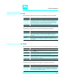
4.1. Syringes
By pressing a Function Key the following functions are available:
Function Key
Description
F1 Chang Syr
The syringe is moved to a position, where the syringe assembly can be completely
lowered to facilitate removal of the syringe adapter. The syringe can then be removed
and replaced. A prompt will be displayed to specify the new syringe. The syringe must
be installed before pressing Enter. (see Chapter 8 "Syringes")
F2 Clean Syr
This Function is used to clean or prime the syringe prior use. After selecting F2 either
Wash1 or Wash2 can be selected.
F3 Set Pos
Set Pos is used to define the Chang Syringe position
F4 HOME
The Injection Unit moves to its HOME position and the Job Queue Menu is displayed.
The following Syringe Parameters may be changed by selecting the particular item:
Item
Description
Actual Id
Indicates the Identification number (ID) of the currently inserted syringe. If the syringe
detection system is set to manual, the extension "man" is displayed. This value can not
be changed.
Fill Volume
This parameter serves to control the filling of the syringe. It may happen that air
bubbles remain below the plunger after the first pull up. If the plunger is moved up
and down several times (see Fill Strokes), these air bubbles are worked out. With this
operation the syringe may be completely filled even when using very small sample
volumes.
Fill Strokes
Number of Fill Strokes. All Fill Strokes, except the last one, use the selected Fill Volume.
If the selected Sample volume is higher than the Fill Volume, the Sample Volume is
used for all Fill Strokes. If zero is selected the plunger is pulled up only once using the
Sample volume value.
Pullup Del
Using this item a delay time between sample pullup and ejection while filling the
syringe can be selected. The same delay time is used after the last plunger pullup until
the syringe needle is moved out of the sample vial/well. It is only used if more than
one Fill Stroke is selected. This feature is especially useful for handling viscous fluids or
syringe sizes >100µl.
Fill Speed
Speed of plunger movement used in all syringe filling operations.
Eject Speed
Speed of plunger movement used in all syringe eject operations except sample
injection.
Inject Speed
Speed of plunger movement for sample injection.
Plunger Pos
Plunger position during Chang Syringe operation. The syringe plunger is moved to a
position, where the syringe can be removed and replaced. The value may be changed
for different types of syringes.
22
IFC PAL User Manual
4.2 Tray
After selecting the particular Tray to be accessed, the following Functions are available:
Function Key
Description
F3 Movto nnn
This function serves as a quick check to determine if the XYZ coordinates are defined
correctly for the selected Tray. To use this utility the selected Tray including the sample
vials or Microplate must be present. After pressing "Movto 001" the Injection Unit
moves to sample position no.1. This procedure can be repeated for the last sample
position in the first row and the last sample position in the last row.
F4 HOME
The Injection Unit moves to its HOME position and the Job Queue Menu is displayed.
The following Tray Parameters may be changed by selecting the particular item:
Item
Description
Needle Penetr
Needle penetration depth into the sample vial. The stored default values for each
Sample Tray Type are approx. 2mm above the sample vial/Microplate bottom. The
needle penetration depth for the selected Tray may be changed by entering the
desired value.
Tray Type
The Tray Type, which is selected for the Tray, is shown. If the Tray enables use of
different Tray Types, it can be changed here. (Alternate use of Microtiter or Deepwell
plates in a Stack)
4.3 Injector
After selecting the particular Injector to be accessed, the following Functions are available:
Function Key
Description
F1 Rinse Inj
After pressing F1, either Wash1 or Wash2 may be used to clean the LC injection valve
port without running a Job.
F2 Act Valve
F2 switches the LC injection valve between the Load and Inject position. It may be
used to test the valve drive function or to perform manual injections.
F3 Movto Inj
The Injection Unit moves to the injection valve position. By selecting the Parameter
"Needle Penetr" on the same screen the Injection Valve Needle Penetration value may
be checked or changed. (see chapter 9.3)
F4 HOME
The Injection Unit moves to its HOME position and the Job Queue Menu is displayed.
The following Injector Parameter may be changed by selecting the particular item:
Item
Description
Needle Penetr
By selecting the Parameter "Needle Penetr" the Injection Valve Needle Penetration
value may be checked and/or changed. To ensure reproducible sample injection and
minimize carryover it is critical that the needle penetration depth is set accurately. (see
chapter 9.3 Injection Valve Needle Penetration)
23
IFC PAL User Manual
4.4 Wash Station
After selecting the specific Wash Station, the following Functions are available:
Function Key
Description
F2 Act Valve
F2 switches the selected Wash Station valve between the Open and Close position. It
may be used to check the valve function or to prime the wash solvent lines.
F4 HOME
The Injection Unit moves to its HOME position and the Job Queue Menu is displayed.
The following Wash Station Parameter may be changed by selecting the particular item:
Item
Rinse Time
Description
"Rinse Time" may be used to expand the solvent flow time through the wash station
glass liners after the last wash stroke is performed and the needle is retracted. If "Rinse
Time" is set to 0, the wash station valve is closed immediately after the last wash
stroke.
4.5 Dilutor
The Dilutor functions are used for the Side-port syringe from the IFC PAL Collector side.
By pressing a Function Key the following functions are available:
Function Key
Description
F1 Prime
This Function is used to prime the solvent lines between the solvent bottle and the
dilutor syringe and the transfer line between the dilutor syringe and the sideport
syringe. After selecting “F1Prime” the dilutor syringe aspirates the volume defined in
Prime Volume and ejects the solvent to the selected Waste position. It may be that
several plunger strokes are needed depending on dilutor syringe size and Prime
Volume. The Function is used prior first time use or after every solvent or syringe
change.
F2 Change
DSyr
The dilutor syringe plunger is moved to a position where the syringe can be removed
from the dilutor module (see page 9 “assembling the PAL dilutor”). A prompt will be
displayed to specify the new dilutor syringe. The syringe must be installed before
pressing Enter.
F3
Not used
F4 HOME
The dilutor syringe moves to it’s Zero position and the Job Queue Menu is displayed.
24
IFC PAL User Manual
The following syringe parameters may be changed by selecting the particular item:
Item
Description
Syringe
Indicates the type of sideport syringe currently used together with the dilutor module.
Syr Dilut Pos
This parameter serves to define the dilute position of the sideport syringe plunger. The
position should be adjusted exactly above the lower hole of the sideport syringe. It
must be verified after every sideport syringe change.
Dilutor Syr
Indicates the type (size) of dilutor syringe currently used.
Prime Volume
The volume used to prime the solvent lines between the solvent bottle and the dilutor
syringe and the transfer line between the dilutor syringe and the sideport syringe
(see page 18, “F1Prime”).
Pullup Del
Using this item a delay time between solvent pullup and ejection while filling the
dilutor syringe can be selected. This feature is especially useful for handling viscous
solvents.
Fill Speed
Speed of dilutor syringe plunger movement used in all syringe filling operations.
Eject Speed
Speed of dilutor syringe plunger movement used in all syringe eject operations.
Eject Delay
Using this item a delay time between solvent eject and next solvent pullup of the
dilutor syringe can be selected. This feature is especially useful for handling viscous
solvents.
25
IFC PAL User Manual
IFC PAL Description and Installation
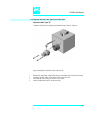
5. General System Overview
5.1 IFC PAL Used for Analytical Flow Rate Range
(Typically 1 ml/min or less)
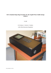
Figure 4. IFC PAL - Major System Components for Analytical Version
The IFC PAL configuration can include a Microplate Stack, Peltier cooled or
not cooled,a 6-port LC Injection Valve and a Fast Wash Station.
In addition, a second valve drive, two additional Microplate Stacks or
Vial Tray Holders can be added.
26
IFC PAL User Manual
5.1.1 Specifications for IFC PAL Analytical Version
General Specifications
Sample capacity
98 x 2ml vials per Tray
200 x 1ml vials per Tray
32 x 10ml / 20ml vials per Tray
6 Deepwell- or Standard Microtiterplates in a 3 drawer Stack
12 Standard Microtiterplates in a 6 drawer Stack
(up to 4 Stacks, Injector and Collector side, may be configured,
max. 24 plates for each side)
Thermostatted Sample Tray
Optional, 4°C – 70°C
Injection volume range
5, 10, 25, 100, 250, 500, 1000, 2500 and 5000 µl syringes are available.
Down to 0.5µl with solvent sandwich injection.
Down to 0.5µl with optional 4-port internal loop configuration.
Up to 5000µl with optional larger loop and syringe.
Replicate injections
1 - 99 from one vial
Wash Station
2 different wash solvents
Precision
Typically < 0.5% RSD of peak area from 10 µl – 100 µl
Typically < 1.0% RSD of peak area from < 10 µl
Carryover
Typically < 0.1%
See specific Specification Data Sheet
Collector Syringe Volume
2, 20, 80, 200 and 800 µl syringes available.
Dead Volume for changes “Collect/Waste” in µl-range.
Injection cycle time
Typically 20 - 60 sec. depending on plunger speeds, injection volume and wash cycles
27
IFC PAL User Manual
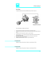
5.2 IFC PAL Used for Preparative Flow Rate Range
(Typically 1 to 100ml/min)
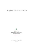
Figure 5. IFC PAL - Major System Components for Preparative Version
The IFC PAL configuration can include at the Injector side a Trayholder,
Microplate Stack, Peltier cooled or not cooled, a 6-port LC Injection Valve
(prep range) and a Fast Wash Station.
At the Collector side can various types of Trayholders be installed to keep
reagent tubes from 13 to 25 mm OD.
In addition a second valve drive (analytical range) can be added.
An optional slider is available to hold standard racks designed for a Gilson System.
28
IFC PAL User Manual
5.2.1 Specifications for IFC PAL Preparative Version
General Specifications
Sample Capacity Injector Side
98 x 2ml vials per Tray
200 x 1ml vials per Tray
32 x 10ml / 20ml vials per Tray
Thermostatted Sample Tray
Optional, 4°C – 70°C
6 Deepwell- or Standard Microtiterplates in a 3 drawer Stack
12 Standard Microtiterplates in a 6 drawer Stack
Injection volume range
100, 250, 500, 1000, 2500 and 5000 µl syringes are available.
Maximum injection volume 20 ml, 4 x 5ml
Loop Volume Range
Loops up to 20 ml are available.
Replicate injections
1 - 99 from one vial
Wash Station
2 different wash solvents
Precision
Typically < 1.0% RSD of peak area
Carryover
Typically < 0.1%
Sample Capacity Collector Side
14 standard Trays to hold reagent tubes with various volumes
Tube OD 25 mm, holding 55 ml, 21 Tubes per Trayholder, total 294 tubes
Tube OD 20 mm, holding 35 ml, 39 Tubes per Trayholder, total 504 tubes
Tube OD 18 mm, holding 27 ml, 50 Tubes per Trayholder, total 700 tubes
Tube OD 16 mm, holding 16 ml, 50 Tubes per Trayholder, total 700 tubes
Tube OD 13 mm, holding 09 ml, 78 Tubes per Trayholder, total 1092 tubes
(Volume given for tubes with 1500 mm height.
Trayholders for tubes with 100 mm height are available.)
Collector Syringe Volume
2, 20, 80, 200 and 800 µl syringes available.
Dead Volume for changes “Collect/Waste” in µl-range.
Injection cycle time
Typically 1 to 3 minutes depending on plunger speeds, injection volume and wash cycles
29
IFC PAL User Manual
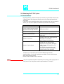
5.3 Electrical Specifications
Parameter
Protection Classa
b
Over Voltage Category
c
Pollution Degree
d
Moisture Protection
Requirement
Class I
Category II
2
Normal (IPXO)
a: Protection Class I:
Protection class describes the insulating scheme used in the instrument to protect the user from electrical shock. Class I identifies a single level of insulation
between live parts (wires) and exposed conductive parts (metal panels), in which the exposed conductive parts are connected to a grounding system. In turn
this grounding system is connected to the third pin (ground pin) on the electrical power plug.
b: Over Voltage Category II:
Over Voltage category II pertains to instruments that receive their electrical power from a local level such as an electrical wall outlet.
c: Pollution Degree2:
This is a measure of pollution on electrical circuits that may produce a reduction of the dielectric strength or surface resistivity.
Degree 2 refers to normally only non-conductive pollution.
Occasionally, however, a temporary conductivity caused by condensation must be expected.
d: Moisture Protection:
Normal (IPXO) – IPXO means that there is NO Ingress Protection against any type of dripping or sprayed water. The X is a place holder to identify protection
against dust if applicable.
30
IFC PAL User Manual
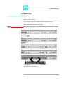
Electrical Specifications (Continued)
Parameter
Requirements
PAL System
Input Voltage
Input Current
Fuse
36 VDC
3.2 A
T6.3 A/250 V
PAL System Power Supply
Input Line Voltage
Input Line Frequency
Input Power
Output Voltage
Output Current
Grounded AC, 100 to 240 V
50/60 Hz
4A
36 VDC
4.16 A
PAL Single Valve Module (Serial Control)
PAL Single, 2-Valve, 3-Valve Module
(Optional Devices)
Input Voltage
Input Current
Fuse
PAL Valve Module Power Supply (Serial control)
Single, 2-Valve, 3-Valve Module
(Optional Devices)
Input Line Voltage
Input Line Frequency
Input Power
Input Fuse
Output Voltage
Output Current
Grounded AC, 100 to 240 V
50/60 Hz
4A
36 VDC
4.16 A
Grounded AC, 100 to 240 V
Stack Cooler DW, MT or Tray Cooler (Peltier Element)
(Optional Devices)
Input Voltage
Input Current
24 VDC
2.7 A
Power Supply for Stack Cooler DW, MT or Tray Cooler
(Peltier Element) (Optional Devices)
Input Line Voltage
Input Line Frequency
Input Power
Output Voltage
Output Current
Output Fuse
Grounded AC, 100 to 240 V
50/60 Hz
2A
24 VDC
4.5 A
T3.15 A/250 V
36 VDC
3.2 A
T6.3 A/250 V
31
IFC PAL User Manual
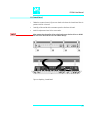
Electrical Specifications (Continued)
PAL IFC-Box
Interface Box for Fraction Collector, A/D Converter
(Optional Device)
Input Voltage
Input Current
Power Supply for PAL IFC-Box
Interface Box for Fraction Collector, A/D converter
(Optional Device)
Input Line Voltage
Input Line Frequency
Input Power
Output Voltage
Output Current
Output Fuse
24 VDC
2.7 A
Grounded AC, 100 to 250 V
50/60 Hz
0.7 – 0.35 A
5 VDC
+15 VDC
- 15 VDC
1.0 A
0.4 A
0.4 A
N/a
32
IFC PAL User Manual
5.4 Physical Specifications
Parameter
IFC PAL Systems Analytical Version
Height
Depth
Width
Weight
Requirements
648 mm (25.5 in)
385 mm (14.1 in.)
1428 mm (56.2 in.) incl. Control Terminal on both sides
20 kg (44 lbs) without accessories
IFC PAL Systems Preparative Version
Height
Depth
Width
Weight
668 mm (26.3 in)
892 mm (35.1 in.)
1428 mm (56.2 in.) incl. Control Terminal on both sides
30 kg (66 lbs) without accessories
5.5 Operating and Environmental Requirements
Parameter
Operating Temperature Range
Maximum Relative Humidity
Bench Space
Vibration
Static electricity
Requirements
4 to 40 oC (39 to 104 oF)
75%, non-condensing
At least 16 cm (6 in.) at the rear, space for fluid waste
container below the instrument and solvent containers next
to the instrument.
Access to power switch(es) and power cord(s).
Clean, level and smooth surface.
Solid bench plate.
Negligible
Negligible
33
IFC PAL User Manual
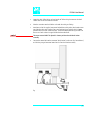
6. Installation
6.1 IFC PAL System Analytical Version
6.1.1 Unpacking the Components
A IFC PAL System is shipped at least in two boxes. One box contains the X/Y Crossrail
assembly, the injection unit, the keypad terminal, standalone supports, connecting cables,
power supply, syringe kit, the injection valve, fast wash station assembly, safety guard and
miscellaneous parts. The other box will typically contain Microplate Stacks and/or
Trayholders.
note !
1
Open the large box containing the X/Y Crossrail. First, remove the Injection Units and the
accessory boxes before attempting to remove the X/Y Crossrail assembly.
2
Remove any loose foam packing around the X/Y Crossrail. Carefully lift the X/Y Crossrail
and remove it from the box. Hold the Y Crossrail in place as the assembly is removed
from the box. Set the X/Y Crossrail assembly on a bench and remove the foam pieces
from each end.
3
Unpack the remaining small boxes and any other containers.
4
Place the IFC PAL onto a stable surface. Make sure that no objects will interfere with either
the Y Crossrail or Injection Unit throughout the entire range of potential movements.
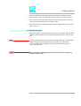
6.1.2 Assembling
The assembling steps are described as an example for a single injection unit. Apply the
same steps if a second unit is required for the IFC PAL System as well.
Before beginning the assembly process, determine approximately where the LC injection
valve will be located. The 2 control terminals will be mounted on either side of the X
Crossrail.
1
If a Stack (a Trayholder with multiple drawers) was shipped with the IFC PAL, loosen the
Torx screws on the two mounting clamps located on top of the stack.
2
Move the Y Crossrail to the center of the X Crossrail and temporarily place the X Crossrail
assembly on top of the stack with the mounting clamp teeth fitting into the grooves on
the bottom of the X Crossrail. The stack should be near the center of the Crossrail.
note !
For IFC PAL’s without a Stack, support the Crossrail in a suitable manner (a sturdy
cardboard box can be used) before attempting to install the legs.
3
Install the legs near the ends of the X Crossrail. Loosen the Torx screws on the mounting
clamps and then fit one leg into the grooves in the X Crossrail. Be sure that the clamps fit
completely into the grooves. Tighten the Torx screws until the legs are firmly in place.
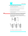
4
Double check if the legs and stack claws are correctly attached to the X Crossrail (see
Figure 6, following page).
34
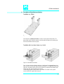
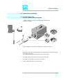
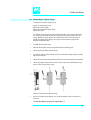
IFC PAL User Manual
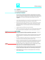
Figure 6. Attachment of Mounting Claws
Installing the Injection Unit
note !
Installation of the Injection Unit should be done carefully. When installing it for the
first time, have someone hold it in place while the mounting screws are inserted (see
Figure 8).
Figure 7. Attaching the PAL Injection Unit
1
Remove the 3 Torx mounting screws A, B and C that will be used to fix the Injection Unit
to the Y Crossrail. Place one of the screws onto the end of the supplied Torx driver. Slide
the clear plastic cover on the Injection Unit all the way to the top.
35
IFC PAL User Manual
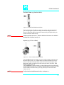
2
Connect the flat ribbon cable A protruding from the front end of the Y Crossrail to the
corresponding connector on the Injection Unit (see Figure 8).
Figure 8. Connecting the Injection Unit Flat Cable
3
Hold the Injection Unit in place against the Y Crossrail. Make sure the two locating pins on
the Y Crossrail fit into the two guiding pin holes on the Injection Unit.
36
IFC PAL User Manual
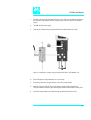
4
Locate the three large holes in the black anodized frame attached to the Z Crossrail inside
the Injection Unit. Slide the frame upwards until the top hole is centered on the top
threaded hole in the end of the Y Crossrail. Insert and securely tighten the Torx screw A
(see Figure 9).
Figure 9. Inserting the Injection Unit Mounting Torx Screws
5
Install the two remaining Torx screws B,
C in the left and right mounting holes,
respectively. It may be necessary to move
the elastic cord slightly to the left to insert
the Torx screw C into the right-hand hole.
Figure 10. IFC PAL with Injection Unit and Standalone Supports
(only 1 injection unit shown)
37
IFC PAL User Manual
Installing the Keypad Terminals and Safety Shield
Figure 11. Installing Keypad Terminals
1
Install the Safety Shield on the left and right sides to the outside of the X-Axis.
2
Install the Keypad mounting brackets on the right and left side of the X Crossrail.
3
Connect one end of the white coiled cables (Part SS8J-700) to the Keypad and the other
end to the two SER3 interfaces jack on the rear side of the X Crossrail.
4
Place the Keypad terminals onto it's mounting brackets.
Installing the Power Supply
note !
1
Locate the power supply, the DC power cables (Part RS3M-2000), and the AC power
cable.
2
Set the power supply switch to the OFF position.
3
Connect one end of the DC power cables to the power supply in the connector “PAL” and
“AUX” and the other ends to the POWER connectors at the rear side of the X-Crossrail.
4
Connect the female end of the AC power cable to the power supply. Then connect the
male end to an AC power outlet.
5
Set the switch on the power supply to the ON position.
6
Observe the Keypads display. The model name “IFC PAL Injector” and “IFC PAL Collector”
will be displayed along with the software version number. The Job Queue menu screen
will then be displayed.
Before proceeding with the remaining steps, switch OFF power to the IFC PAL.
38
IFC PAL User Manual
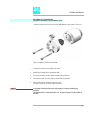
Installing the LC Injection Valve
1
Locate the blue, valve drive. It will have one clamp that is identical to other object
clamps. Loosen the clamp as above (see Figure 12).
Figure 12. Installing the Injection Valve Drive
2
note !
Attach the valve drive to the X Crossrail and tighten the mounting screw.
To avoid unnecessary delay volume between sample injection point and detection,
the injection valve should be located near the detection device.
3
Connect the control cable from the valve drive to AUX1 at the rear of injector IFC PAL
side.
4
The injection valve and rotor is pre-installed on the valve drive.
39
IFC PAL User Manual
Installing the Fast Wash Station
1
Attach the Wash Station assembly to the Solvent bottle holder.
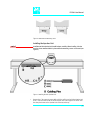
Figure 13 Installing the Fast Wash Station
2
Loosen the screw on the Fast Wash Station mounting clamp.
3
Attach the Fast Wash Station to the X Crossrail as close as possible to the Injection Valve.
This will minimize the time required to move between the two positions.
4
Tighten the mounting screw
.
Figure 14. Fast Wash Station Assembly
40
IFC PAL User Manual
5
Locate the white Teflon fittings and two lengths of Teflon tubing that connect the Wash
Station valves to the wash solvent reservoirs.
6
Place the reservoirs onto their holders and attach the tubing and fittings.
7
Attach one end of the supplied transparent Polyethylene tubing to the Wash station waste
port. Place the other end of tubing into a waste reservoir (not supplied), which is lower
positioned than the Wash station assembly. Stretch the Polyethylene tubing to make sure
that no used wash solvent is trapped before the Waste Reservoir.
note !
The waste reservoir MUST be placed in a lower position than the Wash Station
assembly.
8
Connect the control cable to the connector “Wash Station” at the rear side, Control Board,
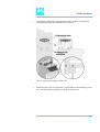
and the four-pronged connector located on the Fast Wash Station assembly.
Figure 15. Electrical Connection Fast Wash Station
41
IFC PAL User Manual
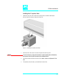
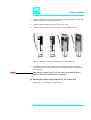
Installing a Microplate Stack
note !
Installation and operation of a Stack or Tray Cooler (Peltier Version) is described in the
Addendum, supplied with every unit.
1
If a Stack (a Trayholder with multiple drawers) was shipped with the IFC PAL, loosen the
two Torx screws on the two mounting clamps located on top of the Stack.
Figure 16. Installing a Microplate Stack
2
Carefully lift the X Crossrail assembly on top of the stack with the mounting clamp teeth
fitting into the grooves on the bottom of the X Crossrail.
3
Be sure that the clamps fit completely into the grooves. Alternately tighten the two Torx
screws until the two mounting clamps are firmly in place.
4
Double check if the Stack clamps are correctly attached to the X Crossrail (see Figure 6).
Installing a Trayholder
1
If a Trayholder was shipped with the IFC PAL, loosen the two Torx screws on the two
mounting clamps located on top of the Trayholder legs.
Figure 17. Installing a Trayholder
42
IFC PAL User Manual
2
Install the Trayholder with the mounting clamp teeth fitting into the grooves on the
bottom of the X Crossrail. The Trayholder should be near the center of the X Crossrail.
3
Be sure that the clamps fit completely into the grooves. Alternately tighten the two Torx
screws until the two mounting clamps are firmly in place.
4
Double check if the two Trayholder clamps are correctly attached to the X Crossrail (see
Figure 5, page 19).
6.1.3.Electrical connections
Before defining the IFC PAL object positions, make sure the LC Injection Valve, Fast Wash
Station and the two Control Terminals are correctly connected to the IFC PAL X-axis rear
side.
note !
note !
The most common Objects for the IFC PAL System, like Injection valve, Fast Wash Station
and one Control Terminal are connected to the IFC Injector side, Control Board.
To the IFC Collector side is typically only the second Control Terminal connected
(CPU and MOTIO Board).
Always switch OFF the PAL power supply before connecting or disconnecting any
IFC PAL accessories cable!
43
IFC PAL User Manual
6.2
IFC PAL System Preparative Version
6.2.1 Unpacking the Components
A ITS PAL System is shipped at least in two boxes. One box contains the X/Y Crossrail
assembly, the injection unit, the keypad terminal, standalone supports, connecting cables,
power supply, syringe kit, the injection valve, fast wash station assembly, safety guard and
miscellaneous parts. The other box will typically contain Microplate Stacks and/or
Trayholders and Trays to hold reagent tubes for collection.
1
Open the large box containing the X/Y Crossrail. First, remove the Injection Units and the
accessory boxes before attempting to remove the X/Y Crossrail assembly.
2
Remove any loose foam packing around the X/Y Crossrail. Carefully lift the X/Y Crossrail
and remove it from the box. Hold the Y Crossrail in place as the assembly is removed
from the box. Set the X/Y Crossrail assembly on a bench and remove the foam pieces
from each end.
3
Unpack the remaining small boxes and any other containers.
4
Place the IFC PAL onto a stable surface. Make sure that no objects will interfere with either
the Y-Crossrail or Injection Unit throughout the entire range of potential movements.
6.2.2 Assembling
note !
The assembling steps described are for the specific preparative parts of the IFC PAL
system. Assembling of the support legs for the slider plate.
The assembling with standard objects, like the Injection valve, Fast Wash Station,
Trayholder , Stacks, etc., is described above under point 6.1 in the section for the
analytical version.
note !
It is important that the IFC PAL for the preparative application is mounted on a solid
bench plate. The bench has to be leveled and has to have a smooth surface.
44
IFC PAL User Manual
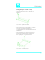
Installing the Support and Slider Assembly
1
Open the transport locking screw using the supplied Allen Key.
See Figure 18.
Figure 18. IFC PAL Support Leg Transport Lock
2
Position the two support legs parallel to each other on the table with
approximately 57 cm distance in-between the two legs.
The support leg with the sensor cable installed at the back side has to
be on the left side.
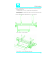
3
Position the two straining pieces in-between the two support legs.
Adjust the distance in-between as perfect as possible to ensure
that the support legs are running parallel to each other.
Figure 19. IFC PAL Straining of Support legs
45
IFC PAL User Manual
4 Screw the straining pieces together with the screws supplied. Leave all screws a little loose,
try to lift the straining pieces into the final position and start tightening all screws overcross. This procedure does ensure that the support legs are positioned parallel.
5 Level out the IFC PAL frame by measuring the distance to the bench plate or by using a
water level device. If necessary make the required corrections with the adjustable legs
from the supports.
note !
It is important that the frame is perfectly leveled out. It will affect the gliding friction
of the slider assembly.
6 Mount the follower pin for the slider assembly at the left side of the slider device as shown
in Figure 20.
Figure 20. IFC PAL Assembling Tray Pan and X-/Y-Axis
7 Mount the X-Y –Axis on the support legs. The same principle applies as described under
point 6.1.2 “Assembling the IFC PAL”.
8 Install the two Injection units as described under point 6.1.2 “Assembling the IFC PAL”.
9 Install the two Keypad Terminals as described under point 6.1.2 “Assembling the IFC PAL”.
46
IFC PAL User Manual
10 Install the Tray Pan starting from the left side where the holes are exactly machined for the
diameter of the of the pins.
The holes at the right side are wider to accept a certain dimension tolerance.
Move the slider assembly manually back and forth to ensure that the bearings are moving
without any friction.
11 Install the safety shield in front of the slider assembly as shown in Figure 20.
Figure 21. IFC PAL Assembly Front View
Figure 22. IFC PAL Assembly as an example configuration
47
IFC PAL User Manual
7. IFC PAL Object Positions
7.1 Defining Object Reference Positions
note !
Remove the Syringe Adapter from the Injection Unit before performing the following
steps.
The objective is to define the Reference Positions for standard IFC PAL Objects. Make sure
the Trayholder(s), Valve(s) and Fast Wash Station are properly mounted to the PAL X-axis.
The following description is an example how to teach the Reference Position for a
Trayholder. The described procedure is common to all IFC PAL Objects.
Fig. 23 Object Reference Position
For Trayholder, the Reference Position is a hole (slightly larger than the lower needle
guide) in the base plate of the Holder. The lower needle guide should be centered in the
hole with the bottom of the needle guide flush with the bottom of the base plate.
1
Switch ON the IFC PAL power supply. When the "Job Queue" menu is displayed,
complete the following sequence (common to all objects):
where "Named Tray Holder" represents a predefined Trayholder (e.g. THldr1 or Stack1).
48
IFC PAL User Manual
Figure 24. Menu Screen Object Trayholder
2 After selecting "Named Tray Holder" (e.g. THldr1 or Stack1), the X Y Z positions for the
selected object will be displayed (see Figure 24).
3 Highlight the item Position X with the cursor bars and press ENTER. The Injection Unit will
move to the previous defined X-axis position.
4 Rotate the outer knob to adjust the X- axis position to the Trayholder Reference Position
(see Figure 23).
5 Press the inner knob to ENTER the Position X value.
6 Repeat steps 3-5 for Position Y and Position Z.
7 Press the F3 button "Moveto Zero". The Injection Unit will move to the HOME position.
8 Verify the defined X Y Z Positions by pressing F1 "Check Pos".
49
IFC PAL User Manual
7.2 Description of Object Reference Positions
Trayholder (e.g. THldr1)
Figure 25. Trayholder Reference Position
For Trayholder, the Reference Position is a hole in the base plate of the Holder. The
lower needle guide should be centered in the hole with the bottom of the needle guide
flush with the bottom of the base plate.
Trayholder with six or three drawers (e.g. Stack1)
Figure 26. Stack Reference Position
For a six drawer Stack the reference position is a hole located in the second drawer (see
Figure 26). For a three drawer Stack the reference position is in the first (top) drawer (see
Figure 26). The lower needle guide must be centered in the hole with the bottom of the
needle guide flush with the bottom of the drawer.
The same logic applies as well to Stack or Tray Coolers. For details see the specific
manual, Addendum supplied with every unit.
50
IFC PAL User Manual
Fast Wash Station (e.g. Wash1 or Wash2)
Figure 27. Fast Wash Station Reference Positions
For a Fast Wash Station the reference positions are two holes above the Wash Station
glass liners (see Figure 27, Wash1 and Wash2). The lower needle guide should be
centered in these holes with the bottom of the lower needle guide lightly touching the
surface of the Wash Station assembly.
note !
The Waste position represents an "Injector" within the PAL software. It is defined in
the Object class "Injectors" (see Fig. 28).
Injectors (e.g. LC Vlv1 or Waste)
Figure 28. LC Valve and Waste Reference Position
For an LC Valve the reference position is the valve needle guide fitting mounted on the
top valve port (see Figure 28). The lower needle guide of the Injection Unit should be
centered in the valve needle guide fitting. Adjust the Z Position that the bottom of the
lower needle guide is just touching the surface of the valve needle guide fitting. Then
reduce the value by 2.0 mm.
For the Waste Port the reference position is a hole (slightly larger than the needle guide)
in front of Wash2 (see Figure 27). The lower needle guide should be centered in this hole
with the bottom of the lower needle guide lightly touching the surface of the Wash
Station assembly.
note !
To adjust the Valve Needle Penetration value, see chapter 9.3.
51
IFC PAL User Manual
Follower Pin for Slider Assembly) Preparative Version
Figure 29. Follower Pin for Slider Assembly, Preparative Version
The reference position for the Follower Pin of the Slider Assembly is the hole at the top of
the tube. See Figure 29.
Adjust the Z-Position of the lower needle guide such that it does enter into the hole. The
higher rim at the back side of the tube has to be in contact with the lower needle guide.
The cut-out in the front of the Follower Pin is reserved for the needle. If longer needles
are used, the cut-out has to be mechanical changed.
Waste Position for Slider Assembly) Preparative Version
Figure 30. Waste Position for Slider Assembly, Preparative Version
For the Waste Port the reference position is a hole (slightly larger than the needle guide)
in front of Wash2 (see Figure 30). The lower needle guide should be centered in this hole
with the bottom of the lower needle guide lightly touching the surface of the Wash
Station assembly.
This waste port is used for clean-up procedures at a stop or abort action.
The wire of the transfer tubing is connected to the screw at the front of the clam.
Safety Warning !
The IFC PAL System used for preparative application has to be grounded with special
care. Organic solvents can be electrostatic charged, resulting sparks can start a fire
hazard.
The screw-connection mounted at the rear side of the clam is used for electrical
grounding. The grounding cable from laboratory has to be connected to this point.
52
IFC PAL User Manual
8. Syringes
8.1 Selecting Syringes
Recommended Syringe for the IFC PAL for analytical application (Injection Side)
1 PAL SyrLC100µl Kit LC Syringe 100µl for HTS PAL,
consisting of:
1 pc syringe adapter
1 pc plunger holder
2 pc syringe SYRC G100-22S-3
The SYRC G100-22S-3 gastight Syringe for IFC PAL, equipped with 22S gauge needle, is
appropriate for injection into the standard CTC injection valve. However, certain
applications may require different syringe sizes or needle ID. Consult the PAL Accessories
Catalog.
Recommended Syringe for the IFC PAL for preparative application (Injection Side)
1 PAL SyrPrep5000µl Kit LC Syringe 5.0 ml for IFC PAL,
consisting of:
1 pc syringe adapter
1 pc plunger holder
2 pc syringe SYRC G5000-19-3
The SYRC G5000-19-3 gastight Syringe for IFC PAL, equipped with 19 gauge needle, is
appropriate for injection into the CTC prep injection valve. However, certain applications
may require different syringe sizes or needle ID. Consult the PAL Accessories Catalog.
Note !
The Needle Dimension for Gauge 19 is: OD 1.07, ID 0.69 mm.
The needle guides (hole for needle) from the injection are adjusted with new
delivered units. Existing units in the field may have to be upgraded.
The Fast Wash Station (P/N MM 01-04F) has to have glass liners with an
internal diameter of 1.50 mm.
Needle Guide and Needle Seal from the injection valve have to be adapted
to Gauge 19. See Chapter 9.
53
IFC PAL User Manual
Recommended Syringe for the IFC PAL for Collector Side, Analytical Version
1 PAL SyrLCSP20µl, Kit Dilutor Syringe for IFC PAL,
consisting of:
1 pc sideport syringe adapter
1 pc sideport plunger holder
1 pc sideport syringe plunger sealing Screw
1 pc sideport syringe 20µl SYRC Sp20-R
3 pc needles gauge 22S for sideport syringe,Ndl S-22S-3
The sideport syringe is used to divert the effluent flow from the HPLC column-detector to
“Collect” or “Waste”.
The needles are replaceable. The recommended needle, is appropriate for injection into
the CTC injection valve. However, certain applications may require different syringe sizes
or needle ID. Consult the PAL Accessories Catalog.
Recommended Syringe for the IFC PAL for Collector Side, Preparative Version
1 PAL SyrLCSP80µl, Kit Dilutor Syringe for IFC PAL,
consisting of:
1 pc sideport syringe adapter
1 pc sideport plunger holder
1 pc sideport syringe plunger sealing Screw
1 pc sideport syringe 80µl SYRC Sp80-R
3 pc needles gauge 19 for sideport syringe,Ndl L-193
The sideport syringe is used to divert the effluent flow from the HPLC column-detector to
“Collect” or “Waste”.
The needles are replaceable. The recommended needle, is appropriate for injection into
the CTC prep injection valve. However, certain applications may require different syringe
sizes or needle ID. Consult the PAL Accessories Catalog.
54
IFC PAL User Manual
8.2 . Syringe Priming
It is critical that syringes be primed before beginning sample preparation. Prime the
syringe by using the Utility function "Clean Syr". For fixed needle syringes, priming may
also be achieved by using an adequate number of filling strokes in a IFC PAL Method,
using the commands from the local terminal.
Gas-tight syringes must be primed manually. Remove the plunger and fill the syringe
from the top of the barrel until solvent either overflows or forms a "bead" at the top of
the syringe. Then insert the plunger.
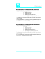
8.3 Installing a Syringe for the IFC PAL Injector Side
1
Select Menu and press F1/Chang Syr. The Injection Unit will move to a location that will
facilitate installation of the syringe.
2
Place the syringe in the appropriate syringe adapter. Pull the plunger out to approximately
20% of it's length.
Figure 31. Syringe and Syringe adapter for IFC PAL Injector Side
55
IFC PAL User Manual
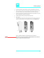
3
If necessary, loosen the plunger retaining screw in the plunger holder (see Figure 32).
4
Move the syringe, installed in the syringe adapter, partially into the Injection Unit. Guide
the needle first into the upper needle guide and then into the lower needle guide.
5
Place the plunger button into the plunger holder. Allow the syringe adapter to "dick" into
place by magnetic force, against the syringe carrier.
6
Tighten the plunger retaining screw against the plunger button.
7
Press "Home".
The plunger moves down until it hits the mechanical stop. This position is stored as the
syringes zero volume position. Then the Injection Unit returns to the HOME position.
Figure 32. Installing and Removing a Syringe from the PAL IFC Injector Side
note !
After replacing a syringe, always check the needle penetration in the LC valve (see
chapter 9.3, Injection Valve Needle Penetration).
56
IFC PAL User Manual
8.4 Removing a Syringe
1
Select "Menu" and press F1/Chang Syr. The Injection Unit will move to a location that
will facilitate removal of the syringe.
2
Loosen the plunger retaining screw. Move the plunger slightly out of the plunger holder.
3
Pull the syringe adapter out and then carefully up to remove the syringe adapter with the
syringe from the Injection Unit.
57
IFC PAL User Manual
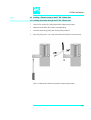
8.5 Installing a Sideport Syringe for the IFC PAL Collector Side
8.5.1 Installing the transfer tubing kit for IFC PAL Collector Side
1
Open the Torx screw at the guiding bracket of the sideport syringe adapter.
2
Locate the transfer tubing kit end with 2 connection fittings
3
Insert the transfer tubing guiding wire into the guiding bracket slit.
4
Adjust the guiding wire in a 90° angle to the bracket and tighten the Torx screw firmly.
Figure 33. Attaching the transfer tubing kit to the Sideport Syringe Adapter
58
IFC PAL User Manual
8.5.2 Installing the Sideport syringe for IFC PAL Collector Side
note !
1
Insert the sideport syringe without plunger into the syringe adapter. Make sure the
syringe side holes are adjusted to the left side.
2
Locate the black connection fitting and screw it into the upper connection thread.
3
Locate the white connection fitting and screw it into the lower connection thread
4
Put the plunger sealing screw over the syringe plunger.
5
Put the black Perfluor O-ring over the syringe plunger.
6
Insert the plunger into the sideport syringe and carefully screw the plunger sealing screw
into the syringe adapter bracket.
It is important to follow the instructions step-by-step. The sideport connections have
to be tightened first to allow the syringe glass barrel to fell into the correct (sealing)
position. After this step one can continue with the step 4 as described above.
Do not over tighten the plunger sealing screw. Check the plunger friction by
manually moving the plunger up and down. Loosen the plunger sealing screw if too
much friction is applied.
Figure 34. Installing the Sideport Syringe for IFC PAL Collector Side
59
IFC PAL User Manual
7
Ensure that the tubing kit connection fittings and it’s guiding wire are attached properly to
the sideport syringe adapter. Also the syringe plunger must be inserted in the sideport
syringe.
8
Turn OFF the PAL power supply
9
Screw on the sideport syringe plunger holder into the black Injection unit slider.
Figure 35. Installing the Sideport Syringe plunger holder for IFC PALCollector Side
10
Pull out the plunger to approximately 20% of it's length.
11
If necessary, loosen the plunger retaining screw in the plunger holder
12
Move the syringe, installed in the syringe adapter, partially into the Injection Unit.
Guide the needle first into the upper needle guide and then into the lower needle guide.
13
Guide the syringe adapter side bracket through the left hand Injection unit slit
60
IFC PAL User Manual
14
Place the plunger button into the plunger holder. Allow the syringe adapter to "dick" into
place by magnetic force, against the syringe carrier.
15
Tighten the plunger retaining screw against the plunger button.
16
Tighten the sideport syringe adapter screw against the black Injection unit slider
Figure 36. Installing the Sideport Syringe Adapter for IFC PAL Collector Side
17
note !
Turn ON the PAL power supply. During the syringe initialization process, the plunger
moves down until it hits the mechanical stop. This position is stored as the syringes zero
volume position
After replacing a sideport syringe in a IFC PAL System, always check the plunger
position as described in Utilities Functions “Syr Dilut Pos”.
8.6 Removing the Sideport Syringe Adapter for IFC PAL Collector Side
Repeat steps 1 – 17 in chapter 8.5 in reverse order.
61
IFC PAL User Manual
9. Injection valve
The IFC PAL can be equipped with different LC Injection valve types.
The recommended valve type for the IFC Pal is the Valco/Vici Cheminert Type Valve.
In the Cheminert product range are valve types for specific applications available.
The Cheminert valve body is available made out of stainless steel or PEAK material
(PEEK related polymer).
For the various ranges of the flow rate are following bore sizes recommended:
- Flow rate range 100 to 500 µl/min :
Bore 0.25 mm
- Flow rate range 500 to 20 ml/min :
Bore 0.40 mm (standard)
- Flow rate range 20 + ml/min :
Bore 0.75 mm
These numbers shall be used as an orientation. The valve selection depends also on the
expected back pressure from the complete HPLC system.
All 3 valve types are delivers with standard Valco 1/16 inch connections.
It is important to use original Valco Ferrules and Nuts to maintain a leak tight connection.
For the PEAK Valve only PEEK Ferrules can be used. Stainless Steel Ferrules are too hard,
one can crack the PEAK Valve Stator by using the wrong ferule material.
The standard rotor material shipped is Valcon H with all valves made out of Stainless
steel. The PEAK-Valve is equipped with a rotor made out of PEEK/Teflon. For special
applications is also a Vespel (Polyimide) rotor available. This material is harder and the
expected life time is therefore shorter.
The selection of the rotor material depends directly from the application.
On customers demand CTC Analytics can also supply the Valco W-Type valve.
This type is only available in stainless steel with a standard bore of 0.40 mm.
The injection loops are available in a wide range from 10 to 5000 µl. All loops have a
1/16 inch tubing at the connection point. The 2 loops for 2.5 and 5 ml have 1/16 inch
connections but the tubing is widened-up to 1/8 inch to eliminate a too high back
pressure.
62
IFC PAL User Manual
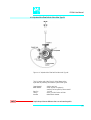
9.1. Injection Valve Flow Path
9.1.1 Injection Valve Flow Path for Valco/VICI Cheminert Valve Type
Figure 37. Standard LC Injection Valve Flow Path, Valco / VICI Cheminert Valve
The standard LC Injection Valve is a 6-port two way switching Valve with
a special needle guide.
Valco / VICI Cheminert Flat Plate Rotary Valve
Stator Material:
Stainless steel 316
Rotor Material:
Valcon H (inert mix-polymer),
standard, can be replaced by other material
Port Size:
1/16 inch
Fittings:
Valco 1/16 inch Ferrules and Nuts
Actuator:
Micro-Electric Actuator
63
IFC PAL User Manual
9.1.2 Injection Valve Flow Path for Valco Valve Type W
Figure 38. LC Injection Valve Flow Path for Valco Valve Type W.
The LC Injection valve, Valco Type W, Conical Rotary Valves
6-port two way switching valve with the special needle guide.
Stator Material:
Rotor Material:
Port Size:
Fittings:
Actuator:
note !
Stainless steel 316
Valcon H (inert mix-polymer)
standard, can be replace by other material
1/16 inch
Valco 1/16 inch Ferrules and Nuts
Micro-Electric Actuator
Sample loops of the two different valves are not interchangeable
64
IFC PAL User Manual
9.2 Valve Needle Guide and Needle Seal
The two valves are equipped with a special valve needle guide fitting. This fitting has a
wide diameter to mate with the syringe needle guide on the injection unit. The valve
needle guide also has a countersunk hole to facilitate insertion of the syringe needle into
the injection port.
Figure 39. Valve Needle Guide and Valve Needle Seal
Example: Valco/VICI Cheminert Valve
(Needle Guide and seal for Valco Valve type W is identical).
Following Needle Guides are available:
- P/N MV 30-12
Needle Guide stainless steel for Gauge 22 needles
- P/N MV 30-16
Needle Guide PEEK for Gauge 22 needles
- P/N MV 30-52
Needle Guide stainless steel for Gauge 19 needles
(marked with a groove at outer rim)
65
IFC PAL User Manual
The valve needle guide holds the needle seal. The needle seal, which is a short length
of Teflon tubing, forms the seal around the syringe needle. A stainless steel ferrule is
tightened around the Teflon sleeve to ensure a leak-proof fit.
Following Needle Seals are available (package of 10 seals):
- P/N PAL NdlSeal
Teflon tube with stainless steel ferrule for Gauge 22 needles
standard Seal for valve bore 0.25 and 0.40 mm,
Teflon transparent
- P/N PAL NdlSealP
Teflon Tube with PEEK ferrule for Gauge 22 needles
Seal for PEAK Valve bore 0.40 mm,
Teflon transparent
- P/N PAL NdlSeal-19
Teflon Tube with stainless steel ferrule for Gauge 19 needles
Seal for Prep-Valve, Bore 0.75 mm.
Teflon blue color.
note !
For the PEAK Valve it is crucial that all ferrules used (for any connection) are made
out of PEEK. Stainless steel ferrules are too hard. One does risk to crack the PEAK
valve stator using a steel ferrule.
note !
To ensure reproducible sample injection and minimize carryover it is critical that:
• The valve needle guide and the valve needle seal are installed properly.
• The valve needle seal is changed every 1500-2000 penetrations.
• The needle penetration depth is set accurately (see chapter 9.3,
Injection Valve Needle Penetration).
66
IFC PAL User Manual
9.3 Injection Valve Needle Penetration
note !
Before performing the following steps, make sure the Object Position X Y Z for LC
Vlv1 (LC Vlv2) are properly defined and a syringe adapter including a syringe is
inserted in the Injection Unit (see chapter 7.2 and 8.3).
Complete the following steps to define the Valve Needle Penetration Depth:
1
In the Object Class "Injectors" choose the Object LC Vlv1. The following screen is
displayed:
Figure 40. Menu Screen Valve Needle Penetration Depth
note !
2
Press the F1 button "Check Pos". The Injection Unit moves to the previous defined LC
Vlv1position.
3
Highlight the item Needle Penetr: with the cursor bars and press ENTER.
4
Slowly rotate the outer knob to adjust the Needle Penetration Depth. The syringe moves
down stepwise into the Injection port.
5
When the syringe needle tip enters the valve needle guide, slow down the Z movement
again. Always observe the syringe needle during this operation step.
6
Move single step wise down until you notice a "click" sound inside the Injection Unit.
STOP immediately the Z down movement.
7
Rotate the outer knob two steps in the opposite direction and press ENTER to save the
Needle Penetration Depth value.
8
Press F3 "Movto Zero".
9
Verify the defined Needle Penetration Depth value by repeating Step 2 and 3.
After all positions have been set and the Valve Needle Penetration has been adjusted
perform a backup of the existing configuration. (see Chapter 11 PAL Loader
Program)
67
IFC PAL User Manual
10. Interfacing the IFC PAL to Other Devices
10.1. Synchronization and Output Signals
Synchronization Signals (Sync Signals) are inputs that tell the HTS PAL when to wait or
proceed with a sample processing step. Output Signals (Out Signals) are sent from the
PAL to external devices to indicate status or completion of particular processing steps.
These signals are classified as Objects. Physical Events (e.g.TTL-In1) are also Objects and
may be assigned to named signals. PAL Cycles require that certain signals such as "Start",
"Inject", and "Injected" be defined. See Table below for the PAL Events and signal
assignments associated with the standard PAL "LC-Inj" Cycle (can be used for the IFC
PAL System or for an “isolated” injection cycle).
The Synchronization Signal shall be set at the IFC PAL Injection Side only. The dedicated
IFC PAL-Software will start the Collector side accordingly.
To assign a physical Event (e.g. SW-Out 1) to an existing signal Object ("Injected")
complete the following menu selections:
PAL's are shipped with all Cycle events pre-defined as shown in the table below. If a
different physical signal needs to be used, then it will be necessary to assign a new Event
to the signal Object.
If a signal is to be ignored, then it's corresponding Event must be set to "Immediat".
Standard Assignment for IFC PAL
Injection Cycles
Description
Default
Events
INTERFACE1
Pin #
Start
Start a cycle (Input from LC or
data system)
TTL-In1
7
8(GND)
(Sync Signal)
Inject
(Sync Signal)
Inject
READY to INJECT
Immediat
(Ignore)
Injected
(Out Signal)
Is activated at the moment when
the sample has been injected
SW-Out1
Running
(Out Signal)
Active as long as the Job Queue is Off
being processed and the PAL is
not in an error state
3
4
68
IFC PAL User Manual
11. PAL Loader Program
The following procedures require a PC with Windows 95/98/NT/2000/XP Operating
System, the supplied PAL Loader program (Version 1.1 or higher), the supplied gray
cable (Part RS9B-3000), and the correct version of the PAL firmware to be loaded.
11.1. Backing Up the PAL Control Program
note !
The following procedure should be performed after the installation of a new PAL
System is completed. Furthermore, periodically System backups ensures that an
updated configuration of the PAL is available any time.
Recommended practice is to create the following directory structure to store PAL firmware
updates and backups:
Directory Path
Contents
C:\ProgramFiles\PAL\Loader\Backup\
Full backup files of current and previous PAL
configurations; includes firmware and parameter settings;
maintained for archival purposes
C:\ProgramFiles\PAL\Loader\Update\
Extracted "Update" files in Loader format (*.sss); may
include firmware only or firmware and parameter settings
1
Shut off power to the PAL and the computer. Connect the supplied gray cable between
the PAL (SER1) and a PC serial port.
2
Switch on power to the PAL. When the PAL Job Menu is displayed, start up the computer.
3
Double-click the PAL Loader icon, the PAL Loader screen appears.
Figure 41. PAL Loader menu screen
4 Click the "Backup" button. A dialog box entitled "Backup Target Memory" will be displayed.
The path (storage location) and file name to be assigned to the new backup will be shown.
A customized path and/or filename may be entered.
Figure 42. PAL Loader Backup Target Memory
69
IFC PAL User Manual
5
Click the "Backup" button.
6
Backup will proceed and information on the backed up components will be
displayed in the "Backup Log:" window. The process will take several minutes. The
message "Backup of Target Memory succeeded" indicates a successful backup.
7
Click the "Close" button to exit the "Backup" dialog box. Click the "Start PAL" button to
terminate control by the Loader program. On the Keypad terminal, the Job Queue screen
is displayed.
8
Disconnect the RS-232 cable from the PAL.
11.2 Reloading a Backup
note !
This operation can potentially overwrite existing parameter settings.
Methods created by the user will be overwritten.
The firmware file to be loaded must reside on the PC hard drive. The file cannot be
loaded from a floppy drive. A full update (including parameter settings) will not fit on a
single floppy diskette in the PAL Loader format. It must be transferred to the PC hard
drive in compressed (*.zip) format and extracted into the "*.sss" file, which is the PAL
Loader format.
Complete the following steps to reload a PAL backup:
1
Shut off power to the PAL and the computer. Connect the grey null modem cable
between the PAL (SER1) and a PC serial port.
2
Switch on power to the PAL. When the PAL Job Menu is displayed, start up the computer.
3
Double-click the PAL Loader icon, the PAL Loader screen appears.
4
Click the "Update" button.
6
Click the "Browse" button and select the appropriate .sss backup file.
7
Click the "Open" button. The "Update Flash Memory" window will be displayed. The
path and filename for the update file will be shown in the "Filename:" entry box.
8
Click the "Update" button to load the new firmware. The process will take several
minutes. If the update is successfully completed, the message. "Update of target
memory succeeded" will be displayed.
9
Click the "Close" button to exit the "Backup" dialog box. Click the "Start PAL" button to
terminate control by the Loader program. On the Keypad terminal, the Job Queue screen
is displayed.
10
Disconnect the RS-232 cable from the PAL.
70
IFC PAL User Manual
12. Troubleshooting
note !
The HTS PAL represents always one of several components in a chromatography
system. The following Troubleshooting Guide is limited to the HTS PAL only.
Symptom or Error Message
Possible Cause
Recommended Action
No or very low detector signal
is observed.
The valve needle guide and / or needle seal are not
properly installed.
Check valve needle guide and seal (see chapter 9.2, Valve Needle
Guide).
The valve ports are not plumbed correctly to the
pump and/or detection system.
Check plumbing connections (see chapter 9.1, Injection valve
flow path).
Wrong valve type specified.
Check valve type by pressing Menu/Setup/Objects/Injectors/LC
Vlv1/Valve.
Clogged syringe.
Remove syringe and aspirate/dispense liquid manually. Clean
syringe.
Bent needle.
Inspect and/or change syringe.
No sample liquid is injected.
Check and/or adjust Needle penetration into sample vial (see
chapter 4.2).
Sample volume too low.
Increase sample volume.
Mobile phase and/or sample
The valve rotor is reversed (180° out of alignment).
flows out of the wrong ports on
the LC injection valve.
Remove the rotor and reinstall in the correct position. Look for a
letter (e.g. "H") stamped on the rotor. The letter must be on the
lower half of the rotor (see chapter 13.3, Valve Rotor).
Sample is backing up on the
valve needle guide.
Syringe needle OD too small.
Check the syringe needle for gauge 22.
Valve needle seal leaks.
Change Valve needle seal (see chapter 9.2, Valve needle Guide).
The needle penetration depth for the injection valve is Adjust the Injection Valve Needle Penetration (see chapter 9.3).
not set correctly.
Poor reproducibility
Excessive carryover between
samples
Unexplained chromatographic
peaks
The Syringe Plunger Speed is too high resulting in
excessive pressure in inlet.
Reduce Inject Speed in method.
Syringe pressure differences when filling the syringe.
Increase Pullup Delay value.
Vacuum created in sample vial.
Reduce sample volume in sample vial.
High volatile solvent.
Use gastight syringe and sample tray cooling.
Increase Pullup Delay value.
Reduce Filling Speed in method.
Not properly crimped vials.
Check vial cap by attempting to rotate by hand. Loose caps may
cause selective loss of lighter components from sample. Adjust
crimping tool correctly
Dirty syringe and/or valve injection port.
Increase Pst Inj Slv1 and or/ Vlv Cln Slv1 values in method.
Use PreClnSlv1 and PreClnSpl.
Waste tubing I.D. at Injection valve is too small
causing waste liquid to be pulled back, by capillary
action, into the rotor groove.
Replace the waste tubing with larger I.D. tubing.
Damaged or grooved valve rotor.
Replace valve rotor (see chapter 13.3, Valve Rotor).
Valve needle seal leaks.
Inappropriate wash solvent.
Change Valve needle seal (see chapter 9.2, Valve needle Guide).
Use appropriate wash solvent.
Air is being introduced into the injection loop. Needle
penetration depths may be inadequate causing air to
be pulled into syringe.
Check and/or adjust Needle Penetration into sample vial (see
chapter 4.2).
Make sure the "Air Volume" Method parameter is set to zero.
71
IFC PAL User Manual
Unexplained collisions of the
Injection Unit
Object(s) not defined correctly.
Error Message
Incorrect Z value for the affected Object (e.g. LC Vlv1,
"Object" Not Detected
Tray1 or Stack1-01).
(Object e.g. Tray1, LCVlv1, Stk101)
Define Object(s) correctly (see chapter 7.1, Defining Object
Positions).
Redefine Z value for the affected Object (see chapter 7.1,
Defining Object positions).
Missing sample vial Deepwell or Microplate.
Insert sample vial, Deepwell or Microplate.
Error Message
"Object" Collision before
Z Tolerance
(“Object” e.g. Tray1, LCVlv1,
Stk1-01)
Incorrect Z value for the affected Object
(e.g. LC Vlv1, Tray1 or Stack1-01).
Redefine Z value for the affected Object (see chapter 7.1,
Defining Object positions).
Error Message
Motor AUX1(AUX2) failed
Injection valve drive not connected.
Switch OFF PAL and check connection between PAL and LC Vlv1
(see chapter 6.3).
Defective LC Vlv1 Connection cable
Change connection cable
MOTIO Board defective.
Replace MOTIO Board (see chapter 13.1, MOTIO Board).
72
IFC PAL User Manual
13. Replacing Parts
13.1 MOTIO Board
note !
1
Follow the sequence shown in Figure 43 to detach and release the MOTIO board from its
position inside the X Crossrail.
2
Carefully pull the two flat cable connectors upwards to free from the board.
3
Install the replacement board in the reverse order.
After reconnecting the two flat cables to the board ensure that the cables are folded
flat and can be slid inside the cross-rail without damage.
Figure 43 Replacing MOTIO Board
73
IFC PAL User Manual
13.2 Control Board
note !
1
Follow the sequence shown in Figure 44 to detach and release the Control board from its
position inside the X Crossrail.
2
Carefully pull the two flat cable connectors upwards to free from the board.
3
Install the replacement board in the reverse order.
After reconnecting the two flat cables to the board ensure that the cables are folded
flat and can be slid inside the cross-rail without damage.
Figure 44. Replacing Control Board
74
IFC PAL User Manual
13.3 CPU Board
1
Remove the right end cover of the Crossrail (facing the rear of the chassis).
2
Slide the CPU board out and towards the right end of the Crossrail. This is necessary
because the CPU board mates on its left side with a connector on the MOTIO board.
3
Install the replacement board in the reverse order
Figure 45 Replacing CPU Board
75
IFC PAL User Manual
13.4 Injection Valve and Valve Rotor
13.4.1 Standard LC Injection valve
Valco /VICI Cheminert, Flat Plate Rotary Valve.
To replace and/or clean the Cheminert injection valve follow the steps
as shown in Figure 46.
Figure 46. Replacing the Standard LC Injection Valve, Valco/VICI Cheminert
1
Remove the sample loop, needle guide fitting and connection tubes from the valve body.
See Figure 35, left picture.
(It is a good practice to label the connection tubes before removal.)
2
Unscrew to the hex screw, which holds the valve to the valve drive
3
Check that the valve guiding pin remains at it's position
4
Install the replacement valve in the reverse order
76
IFC PAL User Manual
Valve Rotor LC Standard Valve
Valco/VICI Cheminert, Flat Plate Rotary Valve
To replace and/or clean the Cheminert valve rotor follow the steps shown in Figure 47
Figure 47. Replacing Cheminert Valve Rotor
note !
1
Unscrew the two hex screws retaining the stator.
2
Remove the old rotor with an appropriate tool.
3
If necessary clean the surfaces without scratching the metal parts.
4
Insert the new rotor, press the polymer disk carefully into position.
5
Put the stator back on, tighten the two hex screws.
The valve is ready for use at the factory-set pressure.
In the event of damage of the stator, replacements or factory refinishing are
available.
The rotor material is Valcon H for HPLC use. The type of material is not marked on
the valve.
77
IFC PAL User Manual
13.4.2Optional Injection Valve Type W and Valve Rotor
Injection valve Type W
To replace and/or clean the injection valve follow the steps shown in Figure 48.
Figure 48 Replacing the Injection Valve, Valco Type W
1
2
3
4
Remove the sample loop, needle guide fitting and connection tubes from the valve body.
Unscrew to the hex screws, which hold the valve to the valve drive
Check that the valve guiding pin remains at it's position
Install the replacement valve in the reverse order
78
IFC PAL User Manual
Valve Rotor
To replace and/or clean the valve rotor follow the steps shown in Figure 49
Figure 49 Replacing Valve Rotor, Valco Type W
1
2
3
4
5
6
7
Do not remove the valve from the valve drive or any tubing or the loop
Unscrew the knurled pre-load assembly. Do not tamper with the preset socket adjustment
screw.
Engage the end of the rotor with a magnet or a pair of tweezers.
Locate the letter (e.g. "H") stamped on the new or cleaned rotor and orient the letter to
the lower half of the valve.
Insert the new rotor. Make sure the rotor tab fits into the slot in the valve drive.
Replace the knurled pre-load assembly.
Tighten the pre-load assembly. It must end up fully bottomed-out.
13.4 Injection Unit
Follow the sequence of steps shown in chapter 6.2 Assembling the IFC PAL.
13.5 Wash Station
Follow the sequence of steps shown in chapter 6.2 Assembling the IFCPAL.
79
IFC PAL User Manual
14. Maintaining the IFC PAL System
14.1 General Maintance
Regularly performing maintenance helps ensure accuracy and precision of the PAL System.
Suggested intervals for maintenance procedures to ensure uninterrupted operation are
given below.
If you use the system heavily (for example, nights and weekends), or if you use aggressive
solvents, you may need to perform the maintenance procedure more frequently.
Maintenance Step
Clean the outside of the instrument.
Use only a soft lint-free paper or cloth
dampened with mild soap and water.
Clean Instrument, syringe and surfaces
Replace the valve needle seal
Replace the valve rotor
Replace the syringe plunger
Interval
Weekly or as needed
Weekly or as needed.
Every 1500 to 2000 penetrations
(Check the tightness of the needle in the
needle seal)
Replace the valve rotor:
Annually or more a year, depending on the
throughput and quality of the
sample solution and Mobile Phase.
Syringe Plunger has to be replaced on
a regular base. The interval is highly
dependent on the application, throughput,
quality of sample solution(particles, etc.)
washing solvent.
It is advisable to check the tightness of
the plunger on a regular base to gain the
experience with the own application.
The other steps are described in the “Preventative Maintenance Procedure”.
Specific kits for the GC or the HPLC techniques are available. The kits include the parts
which shall be changed annually.
PM Kit1 for HPLC and PM Kit2 for GC technique.
note !
There are no operator-serviceable or replaceable parts inside the power supply(ies) or the
PAL System. In case of any failure, contact a representative of CTC Analytics.
80
IFC PAL User Manual
14.2 Maintaining the Sideport Syringe
To maintain the sideport syringe you can:
Inspect the syringe plunger seal
Replace the syringe plunger
Replace the removeable syringe needle
Replace the syringe
The sideport syringe plunger requires periodic replacement. The frequency depends on
the duty cycles, the type of solvents being run through the syringe and the size of the
syringe. Replace the syringe plunger if it is leaking or damaged. To either inspect or
replace the sideport syringe plunger, the syringe or the removable syringe needle
complete the following steps:
1
Turn OFF the PAL power supply
2
Move the PAL Injection unit to a clear position within the working space
3
Loosen the plunger holder retaining screw 1
4
Unscrew the sideport syringe adapter screw 5 and remove the sideport syringe assembly
from the Injection unit.
5
Loosen the two transfer tubing connection fittings 2 but do not remove them completely.
6
Loosen the plunger sealing screw 3 and lift it up 4 (make sure the black Perfluor O-ring
remains in the plunger sealing screw)
Figure 50 Exchanging the Sideport Syringe
7
Inspect the sideport syringe plunger and / or the removeable needle and replace it if
necessary.
To install the sideport syringe again, repeat steps 1–7
81
IFC PAL User Manual
Appendices
A. Definition of Terms
Job Queue
A Job Queue is a list of sample processing Jobs. Jobs are executed in the order displayed
on the JOB QUEUE menu screens. New Jobs may be added to the queue while samples
are being processed.
Job
A Job contains the information needed by the PAL to process multiple samples by the
same processing steps. The elements of a Job are a Method and a Tray that defines the
location of the samples to be processed. For identification, Jobs are automatically
numbered from 01 to 99 and then restarting with 01 when they are added to the Job
Queue.
Cycle
A Cycle consist of the specific operations necessary to process one sample. The Cycle
operations are repeated for each sample within a Job. Cycles are designed for specific
applications. The Standard HTS PAL Cycle is named LC-Inj.
Method
A Method defines how the samples are processed. The elements of a Method are a Cycle,
a Syringe and a Parameter List. Methods have names with up to 8 characters and can be
edited, copied, and deleted.
Method Parameters
Method Parameters are associated with the Cycle operations. User-assigned Parameter
values define how a processing operation is performed. A zero Parameter value will
disable a Cycle operation. Cycle parameters are application-specific.
Object
Objects are data structures describing the properties of physical modules. Certain
modules (e.g. a Stack) require several objects.
Trayholder
A Trayholder can hold one or more trays. Each Trayholder has a reference position
(X, Y, Z co-ordinates) that defines it's location.
Stack
A Stack is a particular type of Trayholder, that is designed to hold micro-plates. A sixdrawer Stack holds 12 standard micro-plates two in each drawer. A three-drawer Stack
holds six deep-well micro-plates two in each drawer.
Tray
A Tray that holds multiple samples. Trays are defined by designating the Tray Type (see
below) and the Trayholder. Tray names are used to identify the sample source within a
PAL Job.
Tray Type
A Tray Type defines the pattern and sampling sequence of sample locations within a Tray.
Standard Tray Types include shallow and deep-well 96-position Microplates and Trays that
hold 1, 2, 10, and 20ml vials.
82
IFC PAL User Manual
B. Conventions of Naming
This section recommends standard naming conventions for HTS PAL Trays, Tray Types,
and Tray holders. Following these conventions will allow HTS PAL's to be pre-configured
for certain applications, will simplify software backups and application development, and
will improve technical support and training.
Tray Type
Tray Description
MT96
Standard 96-position microplates
DW96
Deep well 96-position microplates
MT384
High density 384-position microplates
VT200
Vial Tray, 200 positions (10 X 20)
for 7mm micro-vials, 1.0 ml
VT98
Vial Tray, 98 positions (7 X 14)
for 12mm vials, 2.0 ml
VT78
Vial Tray, 78 positions (6 X 13)
for 7mm micro-vials, 1.0ml
(opposite side of 98 positions Tray)
VT54
Vial Tray, 54 positions (6 X 9)
for 12mm vials, 2.0 ml
(6 Trays may be used in Deep-well Stack PAL Stack6DW)
FC21-55
Fraction Collector Vial Tray, 21 positions (3 x 7)
for 25 mm OD reagent tubes, 150 mm height , 55 ml
FC39-35
Fraction Collector Vial Tray, 39 positions (3 x 13)
for 20 mm OD reagent tubes, 150 mm height , 35 ml
FC50-27
Fraction Collector Vial Tray, 50 positions (5 x 10)
for 18 mm OD reagent tubes, 150 mm height , 27 ml
FC50-16
Fraction Collector Vial Tray, 50 positions (5 x 10)
for 16 mm OD reagent tubes, 150 mm height , 16 ml
FC 78-09
Fraction Collector Vial Tray, 78 positions (6 x 13)
for 13 mm OD reagent tubes, 150 mm height , 9 ml
83
IFC PAL User Manual
C. Injection Cycles
HTS PAL "LC-Inj" Cycle
No. Processing Step
Method Parameter
Object
1 Reference X, Y, Z axis and syringe
plunger
(Class)
Used Object Value
(System)
Start Ref = ON
2 Wait for Start signal
Start
(Sync Signals)
3 Read Barcode if enabled
TRAY
(Tray Type)
4 Syringe wash strokes with solvent
from Wash1
Pre Cln Slv1
SYRINGE (Syringes)
Wash1
5 Syringe wash strokes with solvent
from Wash2
Pre Cln Slv2
SYRINGE (Syringes)
Wash2
6 Rinse syringe with sample selected
number of times
7 Fill syringe with sample using
several filling strokes; aspirate air
outside of vial if Air Volume • 0
8 Move to injection valve
(Wash Stations)
(Wash Stations)
Pre Cln Spl
Sample Volume
Fill Speed
Pullup Delay
SYRINGE (Syringes)
Sample Volume
Air Volume
Fill Speed
Fill Strokes
Pullup Del
SYRINGE (Syringes)
TRAY
Waste
TRAY
(Tray Type)
(Injectors)
(Tray Type)
Barcode • None
Fill Speed
Eject Speed
Needle Penetr
Clean Volume
Max Fill Speed
Max Eject Speed
Fill Speed
Eject Speed
Needle Penetr
Clean Volume
Max Fill Speed
Max Eject Speed
Eject Speed
Fill Volume
Needle Penetr
Needle Penetr
Eject Speed
Overfill
Fill Volume
Needle Penetr
Inject to
9 Wait for Inject signal
Inject
10 Drive needle to penetration depth
Inject to
11 Delay
Pre Inj Del
(Sync Signals)
(Injectors)
Needle Penetr
12 Switch valve to Active position
13 Activate Injected signal
Injected (Out Signals)
Pulse Time
SYRINGE (Syringes)
Fill Speed
Eject Speed
Needle Penetr
Clean Volume
Max Fill Speed
Max Eject Speed
14 Activate Injectd+Signal
15 Dispense syringe contents into
sample loop
Inject Speed
16 Delay
Pst Inj Del
17 Switch valve to Standby position
18 Retract needle from injector
19 Clean syringe and needle with
solvent from Wash1
Pst Cln Slv1
Wash1
(Wash Stations)
84
IFC PAL User Manual
20 Clean syringe and needle with
solvent from Wash2
Pst Cln Slv2
SYRINGE (Syringes)
Wash2
21 Rinse valve inlet with solvent from
Wash1
Vlv Cln Slv1
SYRINGE (Syringes)
Wash1
22 Rinse valve inlet with solvent
from Wash2
23 Move to Home position
Vlv Cln Slv2
(Wash Stations)
(Wash Stations)
Fill Speed
Eject Speed
Needle Penetr
Clean Volume
Max Fill Speed
Max Eject Speed
Fill Speed
Inject Speed
Needle Penetr
Clean Volume
Max Fill Speed
Max Eject Speed
SYRINGE (Syringes)
Fill Speed
Inject Speed
Wash1 (Wash Stations) Needle Penetr
Clean Volume
Max Fill Speed
Max Eject Speed
Home
(Positions)
85
IFC PAL User Manual
"LC-Inj" Cycle Parameter Description
Parameter
Description
CYCLE
LC-Inj Cycle
SYRINGE
Selected syringe
Sample Volume
Selected sample volume
Air Volume
Volume aspirated after the syringe needle is moved out of the sample liquid
Pre Cln Slv1
Pre injection syringe wash strokes with solvent from Wash1
Pre Cln Slv2
Pre injection syringe wash strokes with solvent from Wash2
Pre Cln Spl
Pre injection syringe rinse cycles with sample
Fill Speed
Speed of plunger movement used to aspirate sample
Fill Strokes
Number of filling strokes to aspirate sample
Pullup Del
Delay time between sample pull-up and ejection
Inject to
Name of Injector used for injection
Inject Speed
Speed of plunger movement used during sample injection
Pre Inj Del
Delay time prior sample injection
Pst Inj Del
Delay time after sample injection
Pst Cln Slv1
Post injection syringe wash strokes with solvent from Wash1
Pst Cln Slv2
Post injection syringe wash strokes with solvent from Wash2
Vlv Cln Slv1
Valve rinse cycles with solvent from Wash1
Vlv Cln Slv2
Valve rinse cycles with solvent form Wash2
86
IFC PAL User Manual
D. HTS PAL Software Flow Chart
87
IFC PAL User Manual
88
IFC PAL User Manual
E. External Connectors
Connector SER1
Pin
1
2
3
4
5
6
7
8
9
Signal Name
DCD
RXD
TXD
DTR
GND
DSR
RTS
CTS
RI
Connector SER2 / SER3
Pin
1
2
3
4
5
6
7
8
Signal Name
GND
RXD
TXD
RTS
CTS
+5V
reserved
reserved
89
IFC PAL User Manual
Connector INTERFACE 1
Pin
1
2
3
4
5
6
7
8
9
10
11
12
13
14
15
Signal Name
Pwr-Out1 +
Pwr-Out2 +
SW-Out1 NO
SW-Out1 COM
SW-Out2 NO
Opto-In1 +
TTL-In1
GND
Pwr-Out1 Pwr-Out2 TTL-In2
SW-Out2 COM
TTL-In3
Opto-In1 +5V
Connector INTERFACE 2
Pin
1
2
3
4
5
6
7
8
9
10
11
12
13
14-19
20
21
22
23
24
25
Signal Name
TTL-In1
TTL-In2
TTL-In3
TTL-Out1
TTL-Out2
TTL-Out3
Opto-In1 +
Opto-In2 +
SW-Out1 NO
SW-Out2 NO
Pwr-Out1 +
Pwr-Out2 +
+5V
GND
Opto-In1 –
Opto-In2 –
SW-Out1 COM
SW-Out2 COM
Pwr-Out1 –
Pwr-Out2 –
90
IFC PAL User Manual
Connector AUX1 / AUX2 MOTIO and Control Board
Pin
1,3
2,4
5,7
6,8
10,16,18
11
12
13
14
15,17
19,20
Signal Name
Motor A1
Motor A2
Motor B1
Motor B2
GND
Temp +
Temp –
Sens
+5V
Heater
+36V
Connector WASHSTATION Control Board
Pin
1+
12+
2-
Signal Name
Pwr-Out1+
Pwr-Out1Pwr-Out2+
Pwr-Out2-
91