1
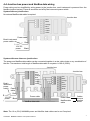
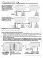
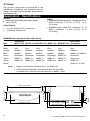
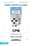
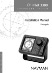
NavBus
with NavBus junction box
w w w. n a v m a n . c o m
Installation and
Operation Manual
NAVMAN
Contents
1 Introducing NavBus ........................................................................................ 3
2 Operation ......................................................................................................... 4
2-1 Introduction ................................................................................................................. 4
2-2 Principles of NavBus ................................................................................................... 4
2-3 Backlight group ............................................................................................................ 4
2-4 Setting an alarm .......................................................................................................... 4
2-5 Muting an alarm ........................................................................................................... 4
3 Parts required .................................................................................................. 5
4 Installation ....................................................................................................... 5
4-1 Position ....................................................................................................................... 5
4-2 NavBus junction box .................................................................................................... 6
4-3 Fitting the cover ........................................................................................................... 6
4-4 Junction box power, NavBus data wiring ...................................................................... 7
4-5 External beeper or lights (alarm) wiring ........................................................................ 8
4-6 Junction box instrument wiring ..................................................................................... 8
4-7 Setup ......................................................................................................................... 10
Appendix A - Specifications ............................................................................ 10
Appendix B - How to contact us ..................................................................... 39
Important
It is the owner’s sole responsibility to install and use the instruments in a manner that will not cause
accidents, personal injury or property damage. The user of this product is solely responsible for observing
safe boating practices.
NAVMAN NZ LIMITED DISCLAIMS ALL LIABILITY FOR ANY USE OF THIS PRODUCT IN A WAY THAT
MAY CAUSE ACCIDENTS, DAMAGE OR THAT MAY VIOLATE THE LAW.
This manual represents the NavBus as at the time of printing. Navman NZ Limited reserves the right to
make changes to specifications without notice.
Governing Language: This statement, any instruction manuals, user guides and other information relating
to the product (Documentation) may be translated to, or has been translated from, another language
(Translation). In the event of any conflict between any Translation of the Documentation, the English
language version of the Documentation will be the official version of the Documentation.
Copyright © 2002 Navman NZ Limited, New Zealand. All rights reserved. NAVMAN is a registered trademark
of Navman NZ Limited.
2
NAVMAN NavBus Installation and Operation Manual
1 Introducing NavBus
NavBus is a NAVMAN proprietary system that allows
multiple 3100 series instruments and NAVMAN
chartplotters to share data and to use a single set of
transducers.
Clusters of up to four instruments are wired to a
NavBus junction box which is then daisy chained via
a two wire data cable to the next cluster and its
NavBus junction box. Power may be run
independently to junction boxes or you may choose
to daisy chain the power as well.
These NAVMAN instruments can be connected by
NavBus: 3100 Series family and any TRACKER 5000
Series chartplotters.
Other compatible instruments can be connected to
a NavBus system by NMEA connections. NMEA is
an industry standard way of connecting instruments
but it requires dedicated connections between
instruments. NMEA cannot be converted to NavBus
and shared using NavBus.
WIND 3100
REPEAT 3100
SPEED 3100
WIND 3100
SPEED 3100
WIND 3100
DEPTH 3100
MULTI 3100
WIND 3100
MULTI 3100
TRACKER 5100
Example systems:
TRACKER 5600
NavBus
Junction box
NavBus
Junction box
REPEAT 3100
NAVMAN NavBus Installation and Operation Manual
Autopilot
NavBus
Junction box
NMEA
NavBus
Junction box
Autopilot
3
2 Operation
2-1 Introduction
Correct installation is critical to the performance of
the instruments. It is vital to read this manual and
the documentation that comes with the instruments
before starting installation.
2-2 Principles of NavBus
All setup data entered into one instrument is
automatically sent to all other instruments of the
same type. For example:
A transducer can be calibrated from any
instrument which can display the transducer’s
readings.
If the units (e.g. feet, metres, fathoms) are
changed on one instrument then the same units
are changed on all instruments.
If setup data such as keel offset, speed
damping or steer angle is set on one
instrument then the same data is set on all
instruments.
The only setup data that is not shared with other
instruments is backlight group, see below.
2-3 Backlight group
Each instrument can be assigned to a backlight
group, which is 0, 1, 2, 3, or 4. If the backlight is
changed on an instrument in group 1, 2, 3 or 4 then
the backlight will automatically change in the other
instruments in the same group. If the backlight is
changed on an instrument in group 0 then no other
instruments are affected.
4
Assign instruments which are mounted close
together the same backlight number: 1, 2, 3 or 4.
Assign isolated instruments to backlight group 0. To
assign an instrument a backlight number, follow the
instructions in the Installation and setup section of
the instrument’s Installation and Operation manual.
2-4 Setting an alarm
Set an alarm on any instrument that can display the
alarm:
Set the too deep or too shallow alarm on any
DEPTH 3100 or MULTI 3100.
Set the wind speed alarm on any WIND 3100.
Note: Refer to the particular instruments operation
manual for specific instructions.
2-5 Muting an alarm
If an alarm sounds, mute it by pressing
on any
instrument which can display that alarm and which
has a key.
Mute a too deep or too shallow alarm on any
DEPTH 3100 or MULTI 3100.
Mute the wind speed alarm on any WIND
3100.
Note 1: Alarms can not be muted from NAVMAN’s
REPEAT 3100.
Note 2: Refer to the particular instruments operation
manual for specific instructions.
NAVMAN NavBus Installation and Operation Manual
3 Parts required
NavBus junction boxes are supplied in two formats: NavBus kit and junction box only.
Parts supplied with complete NavBus kit:
Parts supplied with junction box only:
NavBus junction box.
User manual.
Three ø4 x 16 mm (8g x 5/8") mounting screws.
Five 100 x 2.4 mm (4 x 3/32") cable ties.
NavBus data cable, 10 m (33 ft) twisted pair
tinned wire.
NavBus power cable, 10 m (33 ft) twin flex
tinned power cable.
Note: The instruments are powered from the boat’s
12 V power supply. The positive line should be
protected by a circuit breaker, 10 A recommended. In
addition, each cluster of instruments requires a fuse in
the positive power supply. NAVMAN junction boxes
have the required fuses built in, otherwise fit 1 A fuses.
NavBus junction box.
User manual.
Three ø4 x 16 mm (8g x 5/8") mounting screws.
Five 100 x 2.4 mm (4 x 3/32") cable ties.
NAVMAN accessories are available from your
NAVMAN dealer.
Part numbers:
Description
NavBus Kit
NavBus junction box
(without cables)
10 m (33 ft) data
cable for use with
junction box
10 m (33 ft) power
cable for use with
junction box
Rest of world
AA002616
Europe
43035
AA002617
40647
CB000059
43036
CB000061
43037
NavBus
junction box
NavBus kit
4 Installation
Warnings
The NavBus junction box has a drip-proof cover.
Protect the box from water. The warranty does not
cover damage caused by moisture or water entering
the junction box.
Ensure that any holes that you cut will not weaken
the boat’s structure. If in doubt, consult a qualified
boat builder.
4-1 Position
When fitting the NavBus junction box ensure that
there is sufficient space under the overhang to allow
for removal of cover.
Position the NavBus junction box in a dry place.
Important: Minimum
clearance under
overhang edge 67 mm
(2 5/8")
Always orient the
NavBus junction box
so the lugs are
pointing down.
NAVMAN NavBus Installation and Operation Manual
5
When fitting a NavBus junction box:
4-2 NavBus junction box
The NavBus junction box simplifies wiring systems
of instruments. The box has one four-way terminal
block for attaching power and data cables and four
seven-way terminal blocks for attaching power/data
cables from colour coded NAVMAN instruments.
Orient the box so that the cable tie lugs point
down.
Drill 3 mm (7/64") holes for the mounting
screws provided.
Match the wire colours to the colours of the
terminal block terminals.
After installation, slide the cover back onto the
box.
Note: Minimum clearance under overhang edge
67 mm (2 5/8").
Fuse, 1 A typical
Jumper
Mounting screw
Schematic
Fuse, 1 A typical
Red
Black
Orange
Blue
Green
Yellow
White
Jumper
Note: refer to Appendix A for colour coding
Lugs to hold cable ties
4-3 Fitting the cover
The NavBus junction box cover slides from the top into place.
6
NAVMAN NavBus Installation and Operation Manual
4-4 Junction box power and NavBus data wiring
Power wiring can be simplified by wiring power to the junction box, each instrument is powered from the
NavBus junction box(es). Power is turned on and off by the instrument power switch.
System with one junction box
No external NavBus data cable is required.
Junction box
Red
Black
Orange
Blue
Green
Yellow
White
Power cable
Boat’s instrument
power switch
Red
12 V DC
power
Black
System with more than one junction box
The power and NavBus data cables can be connected together in a star, daisy-chain or any combination of
the two. The maximum total length of NavBus data cable in a system is 100 m (330 ft).
Junction box
Boat’s
instrument
power
switch Power
cable
Red
Black
Orange
Blue
Green
Yellow
White
Junction box
Red
Black
Orange
Blue
Green
Yellow
White
Red
12 V DC
power
Black
Power cable
NavBus data cable
Power cable
NavBus data
cable
Cables
to more
junction
boxes
Note: The 10 m (33 ft) NAVMAN power and NavBus data cables can be cut if required.
NAVMAN NavBus Installation and Operation Manual
7
4-5 External beeper (alarm) wiring
An alarm activates the external alarm on all instruments that are able to display that specific alarm.
Here, the external beepers (or
lights) are connected at one
point. It is only necessary to
connect the external beepers
or lights to a green terminal in
one junction box.
Red
Green
External
beepers
or lights
DEPTH 3100
DEPTH 3100
Red
Red
Green
External
beepers
or lights
External
beepers
or lights
DEPTH 3100
Green
Here, two sets of external
beepers or lights are connected.
All beepers (or lights) will
activate at the same time.
DEPTH 3100
Important: Ensure wires are stripped and tinned.
4-6 Junction box instrument wiring
SPEED 3100, DEPTH 3100, MULTI 3100 or WIND 3100
Wire the instrument’s power/data cable to one of the seven-way terminal blocks in the junction box. An
instrument can be fitted to any terminal block. Wire any REPEAT 3100s to the end terminal block (see
next page), otherwise ensure the jumper is fitted in the junction box (See section 4-2).
Wire any NMEA inputs or outputs required for the instrument to the yellow or white terminals. Ensure
wires are stripped and tinned.
Fit only one transducer of each type. For example, in the diagram below right, there is a DEPTH 3100 and a
MULTI 3100, which both have depth transducer inputs. Fit one depth transducer, to either instrument. In some
circumstances no transducer is required, refer to each instrument’s Installation and Operation manual.
Junction box
Red
Black
Orange
Blue
Green
Yellow
White
Power, NavBus and
external beeper or
lights wiring
8
NMEA inputs or outputs
required for instruments
Power/data cable, to instrument
to depth
transducer
DEPTH 3100
MULTI 3100
NAVMAN NavBus Installation and Operation Manual
REPEAT 3100
REPEAT 3100 is wired slightly differently from other instruments in NAVMAN’s 3100 series family. The green,
yellow and white wires are used for NMEA data also the REPEAT 3100 has no external beeper. Use the far right
terminal block for the REPEAT 3100 and remove the jumper (indicated below). Wire any NMEA inputs to the
REPEAT 3100 directly to the green, yellow or white terminals. Ensure wires are stripped and tinned.
Junction box
Remove the jumper
Red
Black
Orange
Blue
Green
Yellow
White
Power, NavBus and external
beeper or light wiring
Wire the REPEAT 3100 to
this end terminal block only
NMEA data required for REPEAT 3100
Power/data cable, to REPEAT 3100
TRACKER 5000 series chartplotters
Wire the TRACKER’s power/data cable orange, blue and green wires to one of the seven-way terminal
blocks in the junction box. Connect the other wires as described in the TRACKER’s Installation and Operation
manual. Wire any REPEAT 3100s to the end terminal block (see above).
Each TRACKER should have its own 1 A positive power supply fuse. If the TRACKER has the fuel option
fitted, then the TRACKER’s power wire should not be connected to a power supply that can be turned off.
Junction box
Red
Black
Orange
Blue
Green
Yellow
White
Power, NavBus and external
beeper or light wiring
Other wiring (refer to TRACKER’s
Installation and Operation manual)
Power/data and fuel cable,
to TRACKER 5000 series chartplotter
Note:
Instruments that are mounted close together will normally be connected to the same junction box and
will be assigned the same backlight group number, (see section 1-3). Note that this is not mandatory;
an instrument can be assigned any backlight group number.
For more information about installing an instrument, refer to each instrument’s Installation and
Operation Manual. In some circumstances, no transducer is required.
If more than one instrument requires the same NMEA input, wire this separately to each instrument’s
terminal block. Ensure wires are stripped and tinned.
The yellow and white terminals are not linked together in the junction box and can be used as arbitrary
connection points.
Additional power and data cable is available from your NAVMAN dealer in 10 m (33 ft) lengths or you
may supply your own.
NAVMAN NavBus Installation and Operation Manual
9
4-7 Setup
Set up each instrument as described in the
instrument’s Installation and Operation manual.
Assign each instrument a backlight group number
(see section 2-3).
Appendix A - Specifications
NavBus
Maximum total NavBus data cable length:
100 m (330 ft).
Cables
NAVMAN NavBus data cable: Twisted pair, UL 22
AWG (diameter 0.76 mm [1/32"]), 10 m
(33 ft) long.
Power Rating
NAVMAN power cable: Two conductor, UL 18
AWG (diameter 1.5 mm [1/16"]), 10 m
(33 ft) long.
12 V DC nominal (16.5 V maximum).
1 A total per junction box.
NAVMAN Instrument power/data cable wiring
Instrument
5000 series
MULTI 3100 DEPTH 3100 SPEED 3100 WIND 3100 REPEAT 3100 chartplotter
Pwr +
Pwr +
Pwr +
Pwr +
Pwr +
Pwr +
Wire
Red
Black
Gnd
Gnd
Gnd
Gnd
Gnd
Orange
NavBus+
NavBus+
NavBus+
NavBus+
NavBus+
NavBus+
Blue
NavBus-
NavBus-
NavBus-
NavBus-
NavBus-
NavBus- or NMEA in
Green
Ext beeper
Ext beeper
Ext beeper
Ext beeper
NMEA 3 in
Ext beeper
Yellow
NMEA_in
NMEA_in
NMEA_in
NMEA_in
NMEA 2 in
Auto power
White
NMEA_out
NMEA_out
NMEA_out
NMEA_out
NMEA 1 in
NMEA out
Brown
-
-
-
-
-
Power out, 9 V DC
Note:
Gnd
Shield is connected to connector pin 1, the black wire.
77.4 mm (3.07")
131.6 mm (5.18")
70.0 mm (2.75")
77.5 mm (3.05")
10
70.0 mm (2.76")
77.5 mm (3.05")
NAVMAN NavBus Installation and Operation Manual
11.4 mm
(0.44")
39.0 mm (1.53")
155.0 mm (5.94")
40.2 mm 30.5 mm
(1.20")
(1.58")
A 5000 series chartplotter has a second cable, the fuel cable.
The black wire is common and the white wire is NMEA 1 input.
Appendix B - How to contact us
www.navman.com.
NORTH AMERICA
ASIA
MIDDLE EAST
NAVMAN USA INC.
18 Pine St. Ext.
Nashua, NH 03060.
Ph: +1 603 577 9600
Fax: +1 603 577 4577
e-mail: [email protected]
China
Peaceful Marine Electronics Co. Ltd.
Hong Kong, Guangzhou,
Shanghai, Qindao, Dalian.
E210, Huang Hua Gang Ke Mao
Street, 81 Xian Lie Zhong Road,
510070 Guangzhou, China.
Ph: +86 20 3869 8784
Fax: +86 20 3869 8780
e-mail:
[email protected]
Website:
www.peaceful-marine.com
Lebanon and Syria
Letro, Balco Stores,
Moutran Street, Tripoli
VIA Beirut.
Ph: +961 6 624512
Fax: +961 6 628211
e-mail: [email protected]
OCEANIA
New Zealand
Absolute Marine Ltd.
Unit B, 138 Harris Road,
East Tamaki, Auckland.
Ph: +64 9 273 9273
Fax: +64 9 273 9099
Korea
e-mail:
[email protected] Kumho Marine Technology Co. Ltd.
# 604-816, 3F, 1117-34,
Australia
Koejung4-Dong, Saha-ku
NAVMAN AUSTRALIA PTY
Pusan, Korea
Limited
Ph: +82 51 293 8589
Unit 6 / 5-13 Parsons St,
Fax: +82 51 294 0341
Rozelle, NSW 2039, Australia.
e-mail: [email protected]
Ph: +61 2 9818 8382
Website:
Fax: +61 2 9818 8386
www.kumhomarine.com
e-mail: [email protected]
Malaysia
SOUTH AMERICA
Advanced Equipment Co.
Argentina
43A, Jalan Jejaka 2, Taman
HERBY Marina S.A.
Maluri, Cheras 55100, Kuala Lumpur.
Costanera UNO,
Ph: +60 3 9285 8062
Av Pte Castillo Calle 13
Fax: +60 3 9285 0162
1425 Buenos Aires, Argentina.
e-mail: [email protected]
Ph: +54 11 4312 4545
Singapore
Fax: +54 11 4312 5258
RIQ PTE Ltd.
e-mail:
Block 3007, Ubi Road 1
[email protected]
#02-440, Singapore 408701
Brazil
Ph: +65 6741 3723
REALMARINE
Fax: +65 6741 3746
Estrada do Joa 3862,
HP: +65 9679 5903
CEP2611-020,
e-mail: [email protected]
Barra da Tijuca, Rio de Janeiro,
Thailand
Brasil.
Thong Electronics (Thailand)
Ph: +55 21 2483 9700
Company Ltd.
Fax: +55 21 2495 6823
923/588 Thaprong Road,
e-mail:
Mahachai,
[email protected]
Muang, Samutsakhon 74000,
Equinautic Com Imp Exp de
Thailand.
Equip Nauticos Ltda.
Ph: +66 34 411 919
Av. Diario de Noticias 1997 CEP Fax: +66 34 422 919
90810-080, Bairro Cristal, Porto e-mail: [email protected]
Alegre - RS, Brasil.
Vietnam
Ph: +55 51 3242 9972
Haidang Co. Ltd.
Fax: +55 51 3241 1134
16A/A1E, Ba thang hai St.
e-mail:
District 10, Hochiminh City.
[email protected]
Ph: +84 8 86321 59
Fax: +84 8 86321 59
e-mail:
[email protected]
Website: www.haidangvn.com
NAVMAN NavBus Installation and Operation Manual
United Arab Emirates
Kuwait, Oman & Saudi Arabia
AMIT, opp Creak Rd.
Baniyas Road, Dubai.
Ph: +971 4 229 1195
Fax: +971 4 229 1198
e-mail: [email protected]
AFRICA
South Africa
Pertec (Pty) Ltd Coastal,
Division No.16 Paarden Eiland Rd.
Paarden Eiland, 7405
Postal Address: PO Box 527,
Paarden Eiland 7420
Cape Town, South Africa.
Ph: +27 21 511 5055
Fax: +27 21 511 5022
e-mail: [email protected]
EUROPE
France, Belgium and
Switzerland
PLASTIMO INTERNATIONAL
15, rue Ingénieur Verrière,
BP435,
56325 Lorient Cedex.
Ph: +33 2 97 87 36 36
Fax: +33 2 97 87 36 49
e-mail: [email protected]
Website: www.plastimo.fr
Germany
PLASTIMO DEUTSCHLAND
15, rue Ingénieur Verrière
BP435
56325 Lorient Cedex.
Ph: +49 6105 92 10 09
+49 6105 92 10 10
+49 6105 92 10 12
Fax: +49 6105 92 10 11
e-mail:
[email protected]
Website: www.plastimo.de
Italy
PLASTIMO ITALIA
Nuova Rade spa, Via del Pontasso 5
I-16015 CASELLA SCRIVIA (GE).
Ph: +39 1096 8011
Fax: +39 1096 8015
e-mail: [email protected]
Website: www.plastimo.it
Holland
PLASTIMO HOLLAND BV.
Industrieweg 4-6,
2871 RP SCHOONHOVEN.
Ph: +31 182 320 522
Fax: +31 182 320 519
e-mail: [email protected]
Website: www.plastimo.nl
United Kingdom
PLASTIMO Mfg. UK Ltd.
School Lane - Chandlers Ford
Industrial Estate,
EASTLEIGH - HANTS S053 ADG.
Ph: +44 23 8026 3311
Fax: +44 23 8026 6328
e-mail: [email protected]
Website: www.plastimo.co.uk
Sweden, Denmark or Finland
PLASTIMO NORDIC AB.
Box 28 - Lundenvägen 2,
47321 HENAN.
Ph: +46 304 360 60
Fax: +46 304 307 43
e-mail: [email protected]
Website: www.plastimo.se
Spain
PLASTIMO ESPAÑA, S.A.
Avenida Narcís Monturiol, 17
08339 VILASSAR DE DALT,
(Barcelona).
Ph: +34 93 750 75 04
Fax: +34 93 750 75 34
e-mail: [email protected]
Website: www.plastimo.es
Other countries in Europe
PLASTIMO INTERNATIONAL
15, rue Ingénieur Verrière
BP435
56325 Lorient Cedex, France.
Ph: +33 2 97 87 36 59
Fax: +33 2 97 87 36 29
e-mail:
[email protected]
Website: www.plastimo.com
REST OF WORLD /
MANUFACTURERS
NAVMAN NZ Limited
13-17 Kawana St. Northcote.
P.O. Box 68 155 Newton,
Auckland, New Zealand.
Ph: +64 9 481 0500
Fax: +64 9 480 3176
e-mail:
[email protected]
Website:
www.navman.com
39
Lon 174° 44.535'E
NavBus
Made in New Zealand
MN000196C
NAVMAN
Lat 36° 48.404'S