1
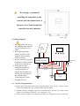
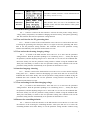
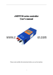
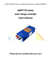
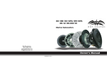
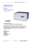
eMPPT60
series
User’s manual
Please read this instruction carefully before you use the machine.
1
Content
1、eMPPT series controller introduction...................................................................................................1
1.1、Features ........................................................................................................................................1
1.2、Product functions.........................................................................................................................1
1.3、MPPT technology introduction ..................................................................................................2
2. Installing instruction..............................................................................................................................2
2.1 Installing dimension........................................................................................................................2
2.2 Wiring diagram...............................................................................................................................3
2.3 Wire & tool preparation..............................................................................................................3
2.4 Installing process ............................................................................................................................4
3. Operating instruction ...............................................................................................................................4
3.1 button function instruction ............................................................................................................4
3.2 LCD interface instruction ..............................................................................................................5
3.3 View the battery parameters..........................................................................................................6
3.4 View and clear for the PV generating data...................................................................................6
3.5 View and set the elevating charging voltage .................................................................................6
3.6 interface language choosing ...........................................................................................................6
3.7 View and setting for the float charging voltage............................................................................6
3.8 Restore the controlling defaults .....................................................................................................6
4. Breakdown disposal..................................................................................................................................7
4.1 Breakdown indication.....................................................................................................................7
4.2 Breakdown and disposal ................................................................................................................7
5. Technical parameters................................................................................................................................8
2
1、eMPPT series controller introduction
1.1、 Features
The product adopts DC/DC converting technology and MCU technology. It can adjust the
working point of the solar panels array intelligently to make the solar panels array realize the
maximum power output. When the external condition changes, the controller bases on the MCU
theory to track the maximum working point of the solar panels, this can improve the using
efficiency of the solar panels and decrease the solar generating cost. Compared with average
solar charge controllers, it can improve the output efficiency of the solar panels by 5% to
30%(the output increasing proportion affected by the factors such as the attribute of the solar
panels, environmental temperature and lighting conditions). The product adopts in big screen
lattice LCD, and uses the vivid icons to indicate the parameters. It has concise and vivid interface.
The product is wall mounting installation. Please refer to chapter 2.1 for the installing
dimensions.
1.2、 Product functions
Functions
Instruction
1
Maximum power
point tracking
Adopting DC/DC converting technology and MCU technology to realize the
maximum output of the solar panels
2
Battery reversed
connection
protection
Battery polarity connecting to the controller reversely (under the condition not
connecting solar panels) will not cause damage to controller. It can work
normally after connecting right.
3
Anti-battery reverse
discharge
When solar panels voltage is less than battery voltage, the battery will not charge
to the solar panels array.
4
Anti-solar panels
reverse connection
Solar panels array polarity connecting to the controller reversely will not cause
damage to controller. It can work normally after connecting right
5
Three-stage charge
control
Bulk、Absorption、Float
6
Float charging
voltage adjustable
The users can adjust the float charging voltage within a certain scope.
7
Temperature
compensation for
float charging
voltage
Referring to the current battery temperature, take 25℃ as a benchmark, the
controller will compensate the float charging voltage by -4mV/Cell/℃. For 12V
battery, compensation voltage U=(t-25)*6*(-0.004)V ; For 24V battery,
compensation voltage U=(t-25)*12*(-0.004)V;For 48V battery, compensation
voltage U=(t-25)*24*(-0.004)V
8
Elevating charging
voltage adjustable
The users can adjust the elevating charging voltage within a certain scope
9
Solar panel input
deviated from
maximum power
point
When solar panel input power is over the acceptable power for the controller, the
controller will make the solar panel work deviated from the maximum power to
prevent itself damaged. So the controller charges the battery by rated current.
10
Internal overheating
protection
When the internal temperature sensor detects excessive temperature, the
controller will stop working to prevent it being damaged. It will resume working
again when the internal temperature drops to a certain degree.
1
11
Temperature
controlling fan
When the internal temperature sensor detects the temperature exceeding a certain
degree, the controller will start the cooling fan until the temperature drops to a
certain degree.
12
Panel over voltage
protection
When the input voltage of the solar panels exceeds the rated voltage, the
controller will start protection automatically and stop working until the input
voltage resumes back to the normal scope.
13
Remote controlling
function
This optional function can make it possible to view and set the parameters of the
system on PC.
1.3、 MPPT technology introduction
MPPT means maximum power point
tracking. MPPT technology is the
technology to track the maximum power
point of the solar panels.
Under a certain condition of
temperature and light, the I-V curve of
the solar panels is as the right chart. The
output power of solar panel is product of
I and V, which means rectangular area of
the points on I-V curve for solar panels.
See the right chart, when the solar panels
work at point A, the output power is
Pa=①+③; when solar panels work at
point B, the output power is Pb=①+②.
Obviously, we can see Pb>Pa. The
purpose of MPPT technology is to keep
the solar panels always working at point
B when the outer conditions change.
2.
Installing instruction
2.1 Installing dimension
2
We strongly recommend
installing the controller on the
vertical wall, and ensure there is
the space over 10cm around the
controller for heat emission.
(uint:mm)
2.2 Wiring diagram
1. We suggest the user to use
the sheathed cable with the
cross-sectional area over
6mm2.
2. We suggest installing
breaker and fuse on the
negative loop of battery
and solar panels.
3. Set the controller’s ground
terminal to reliably connect
to the system ground bus.
4. The capacity of the
controller internal over
voltage absorption is
limited. Please make sure
connect the solar panel to
the controller after
connecting to the mine
exchange line box.
2.3
Solar
Panels
1
+
-
+
-
+ -
The mine
exchange line box
Temperature
sensor
Fuse
Fuse
Fuse
Batterys
array
Wire & tool preparation
⑴ Prepare 6mm2 and 16mm2 black and red sheathed cables, each one roll. Prepare several
copper noses ofФ6-6mm2 since controller adopts inФ6 terminals.
⑵ Hydraulic pliers(for crimping copper nose and cable) and 6 mm2 die, one couple, 10mm
wrench, 2 sets, Phillips screwdriver, 1 set, cutting pliers, 1set
⑶ Cut the cables according to the cabling requirement. Use hydraulic and die to connect the
3
copper nose and cables tightly, and prepare all the cables well.
2.4 Installing process
⑴ If breaker is installed in the battery loop, please make the breaker open. If fuse is installed,
please take out the fuse to prevent the phenomena of contact ignition.
⑵ Use the prepared cables to connect the +,- polarity of battery to the battery terminals on the
controller. Please make sure the connecting of the polarity is correct.
⑶ Use the prepared cables to connect the solar panel output of the main convergence box to
the solar panes terminals on the controller. Please make sure the connecting of the polarity
is correct.
⑷ Use the prepared cables to connect the ground terminals to the ground box of the system.
⑸ Insert the temperature sensor to the right place on the controller.
⑹ Close the breaker of the battery loop or insert the fuse of the battery loop, if the controller
LCD screen starts to show the signal, the controller will start to work. And if the LCD has
no signal, please check whether the connecting of the polarity is correct, whether the
connecting cables is in good condition, whether the breaker is closed, whether the fuse is
inserter. Wait until the LCD has signal, and then go to next step.
⑺ Close the breaker of the solar panels loop or insert the fuse of the solar panels loop, then the
controller LCD screen will show the solar panels voltage. If the LCD shows the voltage is
0V, please check whether the breaker in the solar panels loop is closed.
3. Operating instruction
3.1 button function instruction
Button
Function instruction
+
Press shortly: At the non parameter setting interface, press this button shortly
can turn the page backward. At the parameter setting interface, press this
button shortly will increase the parameter pending to be set.
Press long (over 5s): At the parameter setting interface, press this button long
can increase the parameter pending to set automatically.
-
Press shortly: At the non parameter setting interface, press this button shortly
can turn the page forward. At the parameter setting interface, press this button
shortly will decrease the parameter pending to be set.
Press long (over 5s): At the parameter setting interface, press this button long
can decrease the parameter pending to be set automatically.
OK
Press shortly: At the parameter setting interface, press this button short can
switch to the different parameters in the same interface; at the confirmation
interface, it is used to confirm the current operation; under the circumstances
when the controller detects the breakdown, press this button to the breakdown
indication interface.
Press long (over 5s): At the parameter setting interface, press this button long
and enter inter setting interface, and then press this button long to save the
setting parameter and exit the setting state.
4
ESC
Press shortly: At the parameter setting interface, press this button to cancel
the change for the current parameter; at the confirmation interface, it is used
to cancel the current operation; at the non parameter setting interface, it is
used to switch to the main interface quickly.
Pressing this button long does not have any meaning.
3.2 LCD interface instruction
The showing interfaces consist of 5 interfaces. Each interface has 4 lines. The first line is the
state indication line, and it indicates the working condition of the whole system or the breakdown
information. The icon of the upper right corner of each interface is indication of the current
interface. The first number means the current interface, and the second one means the whole
interface. Please refer to the following form to check the functions of each interface (take 24V
system as an example).
Interface
Interface icon
Interface instruction
Interface
1(main
interface)
It shows the parameters of the system in general:
charging mode, breakdown code, battery voltage,
battery
temperature,
battery
charging
current(controller will show this interface after
opening the system).
Interface 2
It shows the accumulative charging AH today, the total
accumulative charging AH. Operate at this interface to
clear the accumulative charging AH.
Interface 3
The setting interface for elevating charging voltage
and float charging voltage.
Interface 4
he language choosing interface and communication
number setting interface
Interface 5
controller model, fixed version information and
default restoring interface
Interface 6
System language choose and setting page for remote
control’s number
5
Interface 7
Controller’s model, Firmware version information and
The factory default recovery
Breakdown
indication
interface
Breakdown code indication and disposal indication.
This interface does not exist if no breakdown. The
interface comes after the main interface if the system
has breakdown.
3.3 View the battery parameters
Use +, - button to switch to the first interface. It shows the solar panels voltage, battery
voltage, battery temperature, accumulative charging current for battery, solar panels generating
AH. This interface does not have parameter setting function.
3.4 View and clear for the PV generating data
Use +, - button to switch to the second interface. Press OK over 5s and it enters into state
of clearing the generating AH. Then press OK over 5s again to clear the generating AH. Press
ESC to exit the parameter setting interface. The controller will exit the parameter setting
interface automatically if no operation for the button over 20s.
3.5 View and set the elevating charging voltage
Use +, - to switch to the third interface. Press OK over 5s to enter into the parameter
setting interface. Then the parameter pending to set is flickering. Press +, - shortly can adjust
the parameter, and the adjusting margin is 0.1V. Press OK over 5s can save the modified data.
Press ESC shortly can exit the parameter setting interface without saving the modified data.
Then press OK shortly to switch to the next parameter setting. The controller will exit the
parameter setting interface automatically if no operation for the button over 20s.
3.6 interface language choosing
Use +, - button to switch to the forth interface. Press OK over 5s to enter into the language
setting state. Use +,- button to switch to the language you want. Press OK over 5s can save the
modified data. Press ESC shortly will exit the parameter setting interface without saving the
modified data. The controller will exit the parameter setting interface automatically if no
operation for the button over 20s.
3.7 View and setting for the float charging voltage
Use +,- to switch to the third interface. Press OK over 5s to enter into the parameter
setting interface. Then the parameter pending to set is flickering. Press +, - shortly can adjust
the parameter, and the adjusting margin is 0.1V. Press OK over 5s can save the modified data.
Press ESC shortly can exit the parameter setting interface without saving the modified data.
Then press OK shortly to switch to the next parameter setting. The controller will exit the
parameter setting interface automatically if no operation for the button over 20s.
3.8 Restore the controlling defaults
Use +,- button to switch the interface to the fifth interface. Press OK for 5s to enter into
the interface of the restoring the controlling interface. Then press OK for 5s to restore the
controlling defaults. Press ESC shortly to exit the parameter setting interface without saving
6
the modified data. The controller will exit the parameter setting interface automatically if no
operation for the button over 20s.
4. Breakdown disposal
4.1 Breakdown indication
Picture 1
Picture2
When controller detects the breakdown, it will send the breakdown code to the LCD interface,
in the first line (see picture 1), and then it will jump into the suggestive interface to advise the
customer to dispose the breakdown. At the breakdown suggestive interface, press ESC short,
and the controller will show the interface before the breakdown.
4.2 Breakdown and disposal
Breakdown
code
Cause of the breakdown
Disposal
E101
Voltage of Solar panel route 1 exceed the
Maximum limited voltage
Checking whether the serial number of solar
panels rout 1 connect too much
E201
Voltage of Solar panel route 2 exceed the
Maximum limited voltage
Checking whether the serial number of solar
panels rout 2 connect too much
E102
The temperature of radiator with power
module 1 inside the controller is too high,
the power module 1 stop charging the
battery to prevent the damage caused by
overheating. The power module 1 will
resume charging after the internal
temperature recovers to a certain degree.
Checking whether the emission holes
blocked or cover, whether the controller
working condition to high
The temperature of radiator with power
module 2 inside the controller is too high,
the power module 2 stop charging the
battery to prevent the damage caused by
overheating. The power module 2 will
resume charging after the internal
temperature recovers to a certain degree.
Checking whether the emission holes
blocked or cover, whether the controller
working condition to high
E202
E003
Battery voltage is lower than LVP point,
no protection
E104
The temperature sensor for internal
radiator with power module 1 breakdown
or not connecting
7
E204
The temperature sensor for internal
radiator with power module 2 breakdown
or not connecting
E005
Battery voltage too high, no protection
Disconnect other charging appliances
5. Technical parameters
Technical parameters
Model
Input
eMPPT6024Z
eMPPT6048
Solar panel input
voltage scope
≤70V
≤130V
Maximum power point
voltage tracking scope
12V~70V(12V)
24V~70V(24V)
48V~130V
Solar panel input route
2 route
2 route
Rated working voltage
12V/24V auto switch
48V
Maximum charging
current
60A
60A
No load loss
≤50mA
≤50mA
(Bulk、Absorption、Float)
Charging mode
Output
Float charging voltage
27.6V(adjustable)
55.2V(adjustable)
Temperature
compensation
-4mV/cell/℃
-4mV/cell/℃
Absorption charging
voltage
28.8V(adjustable)
57.6V(adjustable)
Temperature scope
-20℃~+80℃
-20℃~+80℃
Protection functions
Others
①
②
③
④
⑤
⑥
Battery reverse connection function
Battery reverse discharging function
Solar panel reverse connection function
Solar panel input over voltage protection
Radiator overheat protection
Input over power deviated from maximum power point
Cooling way
Thermostat active cooling
Optional function
(RS485 or RS232)Remote controlling function
Working temperature
scope
-10℃~+50℃
Working altitude
≤3000m
Working humidity
scope
0~90%,no condensation
Dimension
380mm*283mm*100mm
Weight
Storage temperature
scope
5.7 Kg
5.9 Kg
-30℃~+80℃
8