1
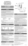
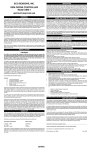
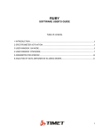
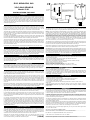
ECO SENSORS, INC.
SeNSOr
hOleS FOr hANGING
reMOve SCrewS ANd COver TO ACCeSS
bATTery
VOC GAS SENSOR
Model C‑21
GAS level
dISplAy
INSTRUCTIONS FOR USE
ON
batt
General
NOTeS: CASE WILL BE WARM TO THE TOUCH
DURING OPERATION. THIS IS NORMAL AND NOT
A CAUSE FOR CONCERN. THE FUSE IS THE
AUTOMATICALLY RESETTING TYPE (AFTER A
FEW MINUTES COOL DOWN.) THERE IS NO
REPLACEABLE FUSE.
AC
The model C‑21 is a solid‑state gas monitor capable of sensing a variety of gases and
vapors. The ones it is generally sensitive to are called VOCS (volatile organic compounds),
and the most common application of the C‑21 is for solvent vapors. Common examples
are paint thinners, dry cleaning fluids, cleaning solvents, and gasoline vapors. The
instrument does not respond to carbon dioxide or radon, and has only a weak response
to carbon monoxide. The C‑21 is self‑contained except for its AC adapter power module.
The instrument also has an audio alarm and has outputs to external alarms, data loggers,
calibration equipment, etc.
MODEL C‑21
VOC SENSOR
pOwer JACK
P‑20 POWER ADAPTER
OUTPUT 12 VDC
300 MA. CTR. +
Alarm Switch Toggle
On (Left)
operation
ON
Off (Right)
OFF
Middle Hole in Back Cover
Plug the AC adapter into AC power and plug the adapter’s output plug into the power jack
on the instrument. After a few seconds, most or all of the display will light up; it will stay
high for 1‑2 minutes; and then it will go down to as low as one green bar. The C‑ 21 will
require at least 3 minutes to warm‑up, and 5 or more minutes is recommended.
The alarm will go on while the instrument’s display is in the red including during warm‑ up.
If this is too objectionable, you may put a muffling cloth such as a towel over the instrument
during warm‑up, or you may switch the alarm off through a hole in the back cover (see
illustration to the top right).
One green bar lit indicates the instrument is receiving correct power. Illumination to the
first yellow bar indicates a cautionary situation for most VOCs, and reaching the first red
bar often indicates a hazardous condition such as reaching the OSHA TLV.
Test the instruments response by holding a fresh felt marker pen a few millimeters from
the sensor grill for a few seconds. The display should light up to red. Check the C‑21’s
response to gases and solvents of interest by exposing the instrument to these VOC’s
and noting its response. The C-21’s response to common VOC’s is shown on the reverse
side of this instruction sheet.
It is best for your protection and for the instrument itself to leave it on 24 hours a day.
installation
The instrument may be hung on hooks, screws, etc. using the outer two top holes on the
back, or it may be stuck to machinery cabinets, etc. using its magnetic backing. Avoid
areas that have a lot of vibration, dust, or dripping or sprayed water. The instrument is not
designed for outdoor use. For dusty or wet areas, the C‑21 should be mounted in the Eco
Sensors EE‑1 Environmental Enclosure which protects it from these hazards.
calibration
The instrument indicates red at high levels of VOC gases and vapors. The C‑21 is broadly
sensitive to most VOCs, but its response is different for each one. To calibrate for a specific
gas, a chemical laboratory is required. The procedure detailed in our Tech Note C‑100.
The perchloroethylene calibration (“perc” or dry cleaning fluid) is shown on the reverse
side of this instruction sheet.
battery operation
To investigate a VOC leak, or to do field research, the instrument may be unplugged from
the AC adapter and operated from its internal rechargeable battery for about 2 hours (This
will not work on initial operation. The battery will require about 10 hours of charging which
happens automatically whenever the instrument is being powered by the AC adapter).
alarm
The audible alarm (buzzer) is normally triggered when the first red segment of the LED
is lit. During warm‑up of the instrument the sensor will read high for 1‑2 minutes and the
alarm will actuate unless it has been turned off.
The alarm set‑point, which is the same set‑point as for the internal relay contacts, can be
changed through resetting the 8 toggle DIP switch found on the circuit board. This switch
allows reconnecting the set‑point across any of the top 8 bars of the LED display. Switch
number 1 connects to the top red bar, all the way down to switch 8 controlling through
the third green bar from the bottom of the display. Please note that no more than one
switch should be down (on) at a time. If no switch is on, the alarm and internal relay will
not work.
Normally, the third switch, corresponding to the first red bar, is on. This switch can be shut
off using a pen or screwdriver actuating it through the upper middle hole in the back plate.
When this is done, neither the alarm nor the internal relay contacts will function.
outputs to external equipment
The C‑21 has two output circuits for external measurements and controls via the accessory
plug. They are (refer to drawing on the reverse side of this instruction sheet):
Low powered (transistor) relay that will switch up to 30 volts at 130 mA directly, or it can
drive an external power‑handling relay that has Its own coil power supply. This relay
closes when the buzzer actuates because it is programmed by the same DIP switch that
controls the buzzer.
0‑2 volts DC output that increases as the VOC level increases. The first red bar on the
LED bargraph corresponds to an output of one volt. The output is not linear, however. It
Is logarithmic (See output table, reverse side of this sheet). This DC output ran be used
to drive data loggers such as the Eco Sensors model DL‑2 for PCs, a digital voltmeter for
remote readout, or the Eco Sensors RAP‑7800 Remote Access Panel. The RAP Panel has
a 90 db alarm, a pulsating red strobe alarm light, and a 4‑20 mA output loop to connect
to a building control system (BCS). For RAP systems be sure to order the C21 with an
interface terminal block.
Use in vehicles
The C‑21 may also be used in cars and trucks, or wherever there is 12 volts DC available.
A cigarette lighter adapter should be purchased for this purpose from an electronics store.
Make sure the plug selected fits our jack (2.5 mm) and that it is configured for center pin
= +. Radio Shack has several models that work such as their part number 270‑029. For
vehicular use, the instruments panel switch should be in the AC position.
Vehicular use includes charging the battery In the C‑21, checking for leaks in solvent
containers, inspection of gasoline station and vehicle maintenance areas, and
environmental checking of roadside hazards and spills.
(Over)
Service and Maintenance
The battery and the sensor are the only user serviceable parts of the instrument. While
they should last 3‑5 years, It is good practice to replace them annually.
Battery The nickel cadmium (NiCad) battery (9 volt snap‑on connector) generally does
not fail suddenly. After about a year, Its performance will gradually decline. The battery
replacement is Eco Sensors part number XB‑C2. NiCad batteries are also available in
local electronics stores such as Radio Shack (part number 23‑526). Both NiCad and
NiMH batteries will work, and both 7.2 volt (6 cell) and 8.4 volt (7 cell) models will work.
The higher voltage version has a somewhat longer discharge life, but the lower voltage
version will charge more efficiently If the AC adapter is only putting out 12‑13 volts (most
“12 volt: AC adapters, like our model P‑20, put out about 15 volts under load). Do NOT
attempt to use alkaline or other non‑chargeable batteries. The non‑rechargeable batteries
will overheat and destroy the instrument, voiding the warranty
The battery may be replaced by disconnecting the AC adapter and removing the back of
the instrument. Exchange the batteries being careful to put the now battery in exactly where
the old one was and to replace the protective felt material surrounding it.
Sensor If the instrument no longer responds to gases and vapors, the likely cause is sensor
failure. The replacement sensor is the Eco Sensors part number SE‑4.
AC Adapter For use in North America and other areas with the “American System” of 120 V
60 HZ, the Eco Sensors P‑20 adapter should be used. For other areas adapters should be
purchased locally that fit local wall sockets and conform to local codes. The output should
be 12 volts DC unregulated, 300‑500 mA. The plug to our instrument should fit a 5.5/2.5
mm socket with the center pin +. For further details see our Tech Note P‑101.
specifications
Sensor: Heated metal oxide semiconductor.
Sensitivity: First responds at a few ppm for many VOC gases and vapors. Alarm typically
sounds at about 50 ppm.
Response time: Within one minute of when gas reaches the sensor.
Audio alarm level: Approximately 80 db.
Temperature and humidity range: 0‑40 deg C and 0‑80% relative humidity.
Supply voltage required: 12 volts DC, 200 mA.
Battery life: Over 2 hours per charge.
Size of instrument: 85 X 35 X 60 mm (3 1/4” X 1 3/8” X 2 3/8”).
Weight of instrument: 140 grams (5 oz.).
Shipping weight of instrument and adapter: about 2/3 kg. (1 1/2 lbs.)
safety features
Enclosure: Self‑extinguishing ABS plastic.
Sensor: Heated element is flame arrestor protected.
Electrical: (a) Circuits operate at 24 volts, 250 mA, or less with no high capacity inductors
or capacitors. (b) Self‑resetting fuse to protect against excess input current flow. (d)
Overvoltage protection diode barrier to protect against supply voltage surges, spikes,
overvoltage, and reverse polarities.
precautions
• Allow at least 5 minutes warm‑up.
• Read all instructions in this manual.
• Keep instrument dry. Never let water or other liquids into the sensor.
• Do not drop the instrument or subject It to continuous vibration.
• Do not store in high levels of dust.
• Do riot clean the instrument with cleaning chemicals or solvents. Clean it with a
damp cloth.
• Do not operate near heavy aerosols (spray) usage or where oxygen Is being
administered.
• Call a qualified electrician If you have any doubts about voltages, currents, electrical
practice, etc.
warranty
This product is warranted against defects in materials and workmanship for one year
following the date of purchase by the original owner. This warranty does riot include damage
to the product as a result of misuse, accident, damage, modifications or alterations, and
it does riot apply if the instructions in this manual are not followed.
If a defect develops during the warranty period, Eco Sensors at its election will repair the
instrument or replace it with a new or reconditioned model of equivalent quality. In the
event of replacement with a new or reconditioned instrument, the replacement until will
continue the warranty of the original unit.
To return the instrument contact your distributor, or call Eco Sensors at (800) 472‑6626
or e‑mail at [email protected] to receive return instructions and a Return Goods
Authorization (RGA) number.
Except as provided herein, Eco Sensors makes no warranties express or Implied, Including
warranties of merchantability and fitness for a particular purpose. Eco Sensors shall not
be liable for loss of use of Oft instrument or other incidental or consequential damages,
expenses or economic low, or claims for such damage or economic loss.
This warranty gives you specific legal rights and you may also have other rights which
vary from state to state.
RECORD YOUR SERIAL NUMBER HERE_ __________________________________
KEEP THIS MANUAL AND WARRANTY FOR YOUR RECORDS.
Eco Sensors is a registered trademark of Eco, Sensors, Inc.
© Eco Sensors, Inc. 2006 Revision 3 for C‑21 REV 1.
For brochures, application and tech notes, and other useful information, visit our extensive
website at www.ecosensors.com. E‑mail us at [email protected].
Eco Sensors Model C‑21
RESPONSE RANGES FOR SOME COMMON VOCs
First detects
Acetone
Benzene
Diacetone alcohol
Formaldehyde
Methylene chloride
Methyl ethyl ketone
Perchloroethylene
Toluene
Trichloroethylene
Alarm
(First red bar)
TLV*
ppm
ppm
ppm
4‑5
5‑10
5‑10
1‑5
8‑10
3‑5
5
3‑5
10‑20
20‑25
25‑50
25‑50
15‑25
40‑50
15‑20
50
15‑25
50‑100
750
10
50
0.1
50
200
50
50
50
DISPLAY CALIBRATION FOR “PERC”
(Partial calibration for perchloroethylene,
the common dry cleaning fluid.)
LED Display
Concentration
ppm
All green
All yellow
One red
Two red
All red
20
40
50
100
140
*Threshold Limit Value. Average estimate of government industrial
hygienists for repeated worker exposure.
C‑21 OUTpUT CIrCUITS
PLUG OUTPUT WIRING COLOR CODING
EARLY VERSION: RED, GREEN, BLACK
CURRENT VERSION: WHITE, RED, BRAID
whITe
Or red
red dC OUTpUT SIGNAl
Or GreeN
relAy CONTACTS
Or brAId
blACK COMMON GrOUNd
0‑2 vOlTS
TO dIGITAl vOlT MeTer, rAp‑7800 reMOTe
CONTrOl pANel Or dATA lOGGer
ACCeSSOry plUG
3.5 MM 2 CIrCUIT
pOwer relAy
TO SwITChed lOAd
SUCh AS FAN Or
OZONe GeNerATOr
relAy pOwer SUpply
12‑24 vOlTS AC Or dC
SUGGeSTed pOwer SwITChING
relAy CIrCUIT
(CUSTOMER SUPPLIED)
The C-21 internal relay is a “dry contact” FET device. It will handle up to 30 volts AC or DC at up to 130
ma so it will switch low voltage alarms directly. For switching power loads an intermediate relay and power
supply should be used such as shown above.
RECOMMENDED ACCESSORIES
EE‑1 Environmental Enclosure For dust and water protection in industrial and agricultural environments
and where the public may be near the instrument. 120 x 180 x 90 mm (5”x 7”x 3”) with a clear polycarbonate
gasket front cover.
DL Series Data Loggers Tiny battery‑operated data loggers record data for later analysis in PCs.
RAP‑2 Remote Alarm Panel In rugged PVC enclosure. Feature 90 dB audio alarm, red alarm strobe
light, 4‑ 20 mA analog signal loop (for building control systems), and optional digital readout.