1
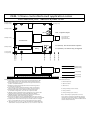
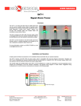
ECO SENSORS, INC.
OPERATION
The OEM-1 is calibrated at the factory by comparison with a NIST traceable UV analyzer.
Lower detection points can be set by the calibrated dial pot R-14 on the main board. Its
numbers represent percentage of ppm. For example, 50 on the dial pot is 50% of .1 or .05
ppm (50 ppb). The calibration as a percentage of .1 ppm should be within 20% over .03-.1
ppm. We do not recommend operating with a set-point for detection below 30% of full
scale because too many chemical, atmospheric, and electronic variables can collectively
make lower set points inaccurate and unreliable. A rough check of the instrument’s
functionality and calibration in abusive environments should be done every three months.
This can be easily done with our model OG-2 Ozone Source Calibrator if the check is at .1
ppm.
OEM OZONE CONTROLLER
Model OEM-1
INSTRUCTIONS FOR USE
GENERAL
The model OEM-1 is a system to control ozone generators and alarms based on an
adjustable ozone concentration set point. It is designed to work with plug-in sensor modules
for 0-.1 ppm, 0-1 ppm, and 0-10 ppm. These are specified when ordering by putting the
ppm range after the model number. For example, a .1 ppm OEM-1 board system would be
OEM-1-.1 and the replacement sensor module for it would be SM-1-.1. These same sensor
modules also work in our OEM-2 boards which have advanced features such as 4-20 mA
output. The sensors modules can also be located at a distance from the OEM-1 boards by
2 or 8 meter cables. These are readily available DIN M/F 5 pin extension cables.
One component of the OEM-1 system is the base board which incorporates the power
supply, final signal processing, set-point controls, and the output relay. The other component
is the sensor mounted with its associated electronics in a cylindrical DIN plug. This is
precalibrated in our lab so that the sensor module and main board module together work
as a calibrated system. If the sensor module is damaged, it is simply replaced by another
precalibrated module.
The design incorporates hysteresis and time delay (set at 8 seconds except for special
orders) to eliminate chatter and other excessive interactions between the sensor and
generator. The SPDT relay contacts will handle up to 5 amps at 250 volts. The OEM-1
should not be used outdoors or in the presence of NOx, nitric acid, acid gases, or halogen
compound fumes.
Allow warm-up according to the table below. At least 24 hours is recommended if the
system hasn’t been used for a week or so. This is because the sensor can absorb VOCs
when it is not in use.
INSTALLATION
CAUTION!
The OEM-1 has exposed high voltage (110/220 V) solder points on the reverse side
of the board from the large transformer. Do not connect high voltage AC power until
you have arranged the board so as not to touch these points. It is best to bench test
the board with a 12 VDC supply (see below). Do not let solder connections on the
OEM-1 board short circuit to any metal surfaces.
The OEM-1 should be attached to your equipment (such as inside the ozone generator)
by four mounting holes. Select four that align with your equipment and which stabilize the
OEM board. The board surface on the solder side should be kept at least 6 mm (1/4") from
any metal surface. The OEM-1 board should be wired to your power by the terminal block
terminals 2 and 3 for 110 V 60 Hz or 220 V 50 Hz according to the power transformer
wiring/jumper diagram found in these instructions. Alternately, you can power the unit by
12 V DC via jack J2. This low voltage power option was provided especially for bench
testing the OEM-1 without exposing personnel to high line voltages. The Eco Sensors P20 AC adapter (a purchase option) can be used to provide 12 VDC when 120 VAC 60 HZ
is available. For 220 V 50 Hz power, you will have to purchase an adapter locally with
specifications according to our Tech Note P-101.
The complete terminal block wiring is:
Terminal
1.
2.
3.
4.
5.
6.
To run AC power “hot” via the OEM-1 relay to the ozone generator high voltage transformer
primary, solder a jumper to connect the two pads under the board that are connected to
the terminal block’s terminals 3 and 5.
If the sensor is not in a high ozone concentration, or hasn’t warmed up, green LED D2 will
illuminate, and will serve for start-up as a pilot light. The yellow LED D1 illuminates when
the relay is activated in response to high ozone. This will happen after a time delay
programmed into the OS-1. 8 seconds is the factory setting if there are no purchase
specifications to the contrary by the purchasing OEM. The delay happens both when the
generator is turned on and when it is turned off. The time delay is determined by the value
of C6, a tantalum capacitor. Removing that capacitor will eliminate the time delay. Time
delays can be selected by multiplying a proposed Tantalum capacitor value by .75. For
example, 4.7uF value for C6 would give about a 3.5 second delay.
WARM-UP
When the generator or other equipment is turned off, if possible, it is best to wire the units
so that the OEM-1 board is always powered. The sensor will stay heated and burn off any
chemicals it would otherwise absorb. When the ozone generator or other equipment is
turned back on, the OEM board is ready to respond immediately and accurately.
Otherwise, warm-ups are required. Recommended warm-up times are:
1 minute - 3 days
3 - 7 days
More than 1 week
10 minutes
1 hour
24 hours
The sensor module can be plugged into the main board directly. It can be extended up to
about 8 meters using standard DIN M/F extension cables (not mini-DIN) available from
most computer supply distributors.
CALIBRATION
The sensor is calibrated in the sensor module by comparison with an NIST traceable UV
analyzer. The accuracy is within 20% at full sensor response.
AC ADAPTER
For using low voltage power input, such as for bench testing, an AC adapter that delivers
12 volts at 300 mA should be used. Its output plug to fit our jack should have the 5.5 mm/
2.5 mm female specification, jack center pin +. These are widely available worldwide. For
more complete specifications see our Tech Note P-101.
SPECIFICATIONS
Sensor: Heated metal oxide semiconductor.
Range: 0-.1 ppm, 0-1 ppm and 0-10 ppm available. Accuracy: 20%.
Sensitivity: As low as .02 ppm for the .1 ppm module, .1 ppm for the 1 ppm module, and .3
ppm for the 10 ppm module. These sensitivities will decrease if sensor module extension
cables are used.
Response time: Within 10’s of seconds.
Turn-on, turn-off time delay: 8 seconds standard. Other times by request.
Temperature and humidity range: The calibration is only valid for normal room temperature
and humidity. The circuit does not include temperature or humidity compensation devices.
Supply voltage required: 110 VAC or 220 VAC per OEM specification. Alternately, 12 VDC
at 300 mA.
Relay ratings: SPDT non-latching. Contacts: 5 amps at 250 volts AC.
Size of main board: 83 X 83 mm (3.25” X 3.25”). Required 23 mm (.875”) clearance from
top surface of board and 6 mm (.250”) clearance from bottom surface of the board.
Main board mounting: By 4 3.5 mm screws (or 6–32 screws).
Sensor Module: 16 mm (dia) X45 mm (length), (.62” X 1.75”), 10 g (.3 oz)
Shipping weight: Both modules and 2 meter sensor extension cable, no adapter: 454 g (1 lb)
PRECAUTIONS
•
•
•
•
•
A typical ozone generator control would be for the hot wire to the primary of the generator
high voltage transformer to be broken and connected through terminals 4 and 5 of the
terminal block. This is the normally closed (N.C.) relay contact. Terminals 5 and 6 are a
normally open (N.O.) circuit and could be used, for example, to connect to remote alarm
circuits.
Warm-up Time
The sensor, which protrudes from the end of the sensor module, is a heated metal oxide
(HMOS) sensor. It incorporates the latest IC and micromachining technology in its
construction so it is very stable and rugged. It can easily lose its calibration - at least until
it is burned-in again - if it is exposed to any VOC chemicals and fumes, especially if it is
exposed to these when it is not powered. These harmful fumes and chemicals include
grease and oils, finger oil, strong deodorants, solvent fumes, sulfur compounds and the
like. The sensor cannot be user calibrated. It should be recalibrated by an authorized
distributor or by the factory. If it is damaged, a new sensor module must be purchased.
•
•
•
Circuit board ground.
AC power connection - neutral.
AC power connection - hot.
Relay normally closed contact (N.C.).
Relay common.
Relay normally open contact (N.O.).
Time Since Last Powered
CARE AND USE OF THE SENSOR
Read all instruction in this manual.
Review safety procedures in testing and operating this system
Call a qualified electrician if you have any doubts about voltages, wiring, electrical
codes and practices, etc.
Keep the boards and sensor dry. Never let water or other liquids into the system.
Do not drop the boards. Damage may not be immediately obvious.
Operate this system in areas of normal room temperature. Operation at lower
temperatures, such as warehouses or refrigerated areas, should only be attempted
after testing in the proposed environment for correct and reliable operation.
Do not attempt to service the instrument yourself.
Do not operate this system or rely on its operations where there are high concentrations
of:
•
•
•
•
•
Chlorine or other halogen compounds
Sulfur compounds.
Nitrides of oxygen (NOx).
Urine residues and ammonia compounds.
Acid gases and vapors such as sulfuric or nitric acid fumes.
When in doubt, operate the system at least 24 hours in your worst case environment.
LIMITED WARRANTY
This product is warranted against defects in materials and workmanship for own year
following the date of purchase by the OEM. This warranty does not include damage to the
product as a result of misuse, damage, modifications or alterations, and it does not apply
if the instructions in this manual are not followed.
If a defect develops during the warranty period, Eco Sensors at its election will repair the
product or replace it with new or reconditioned product of equivalent quality. In the event of
replacement with a new or reconditioned product, the replacement will continue the warranty
of the original model.
To return this system or any module of it, call your distributor or OEM. OEMs and distributors
call Eco Sensors at (800) 472-6626 or e-mail at: [email protected] to receive return
instructions and a Return Goods Authorization (RGA) number.
Except as provided herein, Eco Sensors makes no warranties, express or implied, including
warranties of merchantability and fitness for a particular purpose. Eco Sensors shall not
be liable for loss of use of this instrument or other incidental or consequential damages,
expenses or economic loss, or claims for such damage or economic loss.
RECORD YOUR SERIAL NUMBER HERE______________________________________
KEEP THIS MANUAL AND WARRANTY FOR YOUR RECORDS.
If the sensor is easily accessible, the warm-up time can be minimized by checking for full
response by an ozone generator of known output. The Eco Sensors OG-2 Ozone Source
Calibrator is a portable battery-operated source which is designed to check for response
at .1 ppm.
(OVER)
Eco Sensors is a registered trademark of Eco Sensors, Inc.
© Eco Sensors, Inc. 2000
Rev. 3/02
OEM-1 Ozone controller board application notes
Eco Sensors, Inc. Santa Fe, NM. USA
3.250 [82.550]
3.125 [79.375]
Ì0.125 [3.175]
J2
2.625 [66.675]
R14: Setpoint adjust
R14
Sensor Element
0.400 [10.16]
typical diameter
1.625 [41.275]
Transformer
Terminal Block
0.625 [15.875]
1
2
3
4
5
6
Relay
D2
D2 (Green): On when below setpoint
D1
D1 (Yellow): On when relay energized
3.850 [97.790]
3.500 [88.900]
3.125 [79.375]
2.625 [66.675]
0.625 [15.875]
0.000 [0.000]
0.125 [3.175]
0.125 [3.175]
0.000 [0.000]
0.875 [22.225]
0.662 [16.828]
0.263 [6.668]
0.000 [0.000]
Mounting surface
Installation Notes
1. Line voltage is present on the board around terminal block TB1.
Allow at least 0.250 inches (6.35 mm) clearance behind board.
2. All mounting holes are connected to circuit ground and also to
position 1 of terminal block.
3. Maximum component height above board mounting surface
is 0.875 inch (22.25 mm).
4. Sensor plug is shown mounted directly to main circuit board,
however extension cables may be used for remote mounting.
5. Potentiometer R14 controls detector switching threshold.
In standard configuration, 100% of scale equals 0.1 PPM.
6. LED D1 (yellow) is illuminated when detected level is greater than
threshold seting and relay is energized (after time delay).
7. LED D2 (green) is illuminated when detected level is less than
threshold setting. Responds quickly to changes.
8. Connector J2 may be used to supply DC power (12 Volts nominal,
center pin positive) to board for bench testing to reduce shock hazard.
9. Jumper pads on back of board may be used to select line voltages
of 110 or 220 VAC and to tie relay contacts directly to line supply.
10. Mounting holes are 0.125" / 3.175 mm diameter. Maximum outer
diameter for screws, standoffs, washers, etc. is 0.25 inch / 6.35 mm.
0.250 [6.350]
Terminal Block Pinout
1. Ground (chassis).
2. AC line neutral.
3. AC line hot.
4. Relay normally closed conatct.
5. Relay common.
6. Relay normally open contact.
Note: Board may be jumpered to connect
relay common to AC line hot without external
connection to terminal number 5. NC and NO
contacts will thus provide switched AC for direct
control of external devices.