1
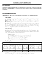
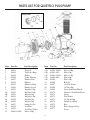
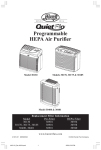
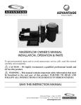
ADVANTAGE
POOL PUMPS
QUIETFLO PLUS OWNER’S MANUAL
INSTALLATION, OPERATION & PARTS
To prevent potential injury and to avoid unnecessary service calls, read this manual
carefully and completely.
CAUTION – We highly recommend a qualified professional install and
service this product.
WARNING – This manual contains important safety information that must
be furnished to the end user of this product. FAILURE TO READ AND
FOLLOW ALL INSTRUCTIONS COULD RESULT IN SERIOUS INJURY.
SAVE THIS INSTRUCTION MANUAL
624 South B Street • Tustin, CA 92780
Toll Free: 800.636.8866 • Tel: 714.505.1166 • Fax: 714.505.1160
advantageman.com
IMPORTANT SAFETY INSTRUCTIONS
Before installing or servicing this electrical equipment, turn power supply OFF.
Basic safety precautions should always be followed, including the following: Failure to follow
instructions may result in injury.
This is the safety-alert symbol. When you see this symbol on your pump manual, look for one
of the following signal words and be alert to the potential for personal injury.
WARNING warns about hazards that could cause serious personal injury, death or major
property damage and if ignored presents a potential hazard.
CAUTION warns about hazards that will cause or can cause minor or moderate personal
injury and/or property damage and if ignored presents a potential hazard. It can also make
consumers aware of actions that are unpredictable and unsafe.
The NOTICE label indicates special instructions that are important but not related to hazards.
WARNING – Read and follow all instructions in this
owner’s manual and on equipment. Failure to follow
instructions can cause severe injury and/or death.
WARNING – This product should be installed and serviced only by a qualified professionals.
CAUTION – All electrical wiring MUST be in conformance with all applicable local codes,
regulations, and the National Electric Code (NEC).
ATTENTION INSTALLER – ThIS mANUAL CONTAINS ImpORTANT INFORmATION ABOUT
ThE INSTALLATION, OpERATION, AND SAFE USE OF ThIS pUmp ThAT mUST BE
FURNIShED TO ThE END USER OF ThIS pRODUCT. FAILURE TO READ AND FOLLOW ALL
INSTRUCTIONS COULD RESULT IN SERIOUS INJURY.
WARNING – To reduce risk of injury, do not permit children to use or climb on this product. The
ANSI/NSPI 4 Standard (above-ground and on-ground pools) advises that components such as the filtration
system, pumps, and heaters be positioned to prevent their being used as a means of access to the pool by young
children. Closely supervise children at all times.
CAUTION – The QUIETFLO PLUS Pump is intended for use on permanently installed above-ground
swimming pools and may also be used with hot tubs and spas if so marked. Do NOT use with storable pools.
A permanently installed pool is constructed in or on the ground or in a building such that it cannot be readily
disassembled for storage. A storable pool is constructed so that it is capable of being readily disassembled for
storage and reassembled to its original integrity.
Though this product is designed for outdoor use, it is strongly advised to protect the electrical components
from the weather. Select a well-drained area, one that will not flood when it rains. It requires free circulation
of air for cooling. Do not install in a damp or non-ventilated location.
2
Bond motor to pool structure. Use a solid copper conductor, size or larger. Run wire from external bonding
lug to reinforcing rod or mesh. Connect a No.8 AWG (8.4 mm2) solid copper bonding wire to the pressure
wire connector provided on the motor housing and to all metal parts of swimming pool, spa, or hot tub, and to
all electrical equipment, metal piping or conduit within 5 ft. (1.5 m) of inside walls of swimming pool, spa, or
hot tub. (In Canada use No.6 AWG bonding wire.)
WARNING – Pool and spa components have a finite life. All components should be inspected
frequently and replaced at least every ten years, or if fund to be damaged, broken, cracked, missing, or not
securely attached.
WARNING – Risk of Electric Shock. All electrical wiring MUST be in conformance
with all applicable local codes, regulations, and the National Electric Code (NEC). Hazardous
voltage can shock, burn, and cause death or serious property damage. To reduce the risk of electric
shock, do NOT use an extension cord to connect unit to electric supply. Provide a properly located
electrical receptacle. Before working on pump or motor, turn off power supply to the pump.
WARNING – To reduce the risk of electric shock replace damaged wiring immediately. Locate
conduit to prevent abuse from lawn mowers, hedge trimmers and other equipment.
WARNING – It is recommended to install a Ground Fault Circuit Interrupter (GFCI) in the circuit,
however, all electrical wiring MUST be in conformance with all applicable local codes, regulations, and the
National Electric Code (NEC).
WARNING – Failure to bond pump to pool structure will increase risk for electrocution and could
result in injury or death. To reduce the risk of electric shock, see installation instructions and consult a
professional electrician on how to bond pump. Also, contact a licensed electrician for information on local
electrical codes for bonding requirements.
Notes to the electrician:Use a solid copper conductor, size 8 or larger. Run a continuous wire from external
bonding lug to reinforcing rod or mesh. Connect a No.8 AWG (8.4 mm2) solid copper bonding wire to the
pressure wire connector provided on the motor housing and to all metal parts of swimming pool, spa, or hot
tub, and to all electrical equipment, metal piping (except gas piping), and conduit within 5 ft. (1.5m) of inside
walls of swimming pool, spa, or hot tub. ImpORTANT – Reference NEC codes for all wiring standards
including, but not limited to, grounding, bonding and other general wiring procedures.
WARNING – Suction Entrapment hazard. Suction in suction outlets and/or
suction outlet covers which are damaged, broken, cracked, missing, or unsecured cause severe
injury and/or death due to the following entrapment hazards:
hair Entrapment – Hair can become entangled in suction outlet cover.
Limb Entrapment – A limb inserted into an opening of a suction outlet sump or suction outlet cover that is
damaged, broken, cracked, missing, or not securely attached can result in a mechanical bind or swelling of the
limb.
Body Suction Entrapment – A differential pressure applied to a large portion of the body or limbs can result
in an entrapment.
Evisceration/ Disembowelment – A negative pressure applied directly to the intestines through an unprotected
suction outlet sump or suction outlet cover which is damaged, broken, cracked, missing, or unsecured can
result in evisceration/disembowelment.
mechanical Entrapment – There is potential for jewelry, swimsuits, hair decorations, fingers, toes, or knuckles
to be caught in an opening of a suction outlet cover resulting in mechanical entrapment.
3
WARNING – To Reduce the risk of Entrapment hazards:
– When outlets are small enough to be blocked by a person, a minimum of two functioning
suction outlets per pump must be installed. Suction outlets in the same plane (i.e. floor
or wall), must be installed a minimum of three feet (3’) [0.91 meter] apart, as measured
from near point to near point.
– Dual suction fittings shall be placed in such locations and distances to avoid “dual blockage” by a user.
– Dual suction fittings shall not be located on seating areas or on the backrest for such seating areas.
– Never use pool or spa if any suction outlet component is damaged, broken, cracked, missing, or not securely
attached.
– Replace damaged, broken, cracked, missing, or not securely attached suction outlet components immediately.
– In addition to two or more suction outlets per pump installed in accordance with latest IAF (formerly NSPI)
standards and CPSC guidelines, follow all national, state, and local codes applicable.
– Installation of a vacuum release or vent system, which relieves entrapping suction, is recommended.
WARNING – hazardous pressure. Pool and spa water circulation systems operate
under hazardous pressure during start-up, normal operation, and after pump shut-off. Stand
clear of circulation system equipment during pump start-up. Failure to follow safety and
operation instructions could result in violent separation of the pump housing and cover due to
pressure in the system, which could cause property damage, severe personal injury, or death.
Before servicing pool and spa water circulation system, all system and pump controls must be in off position
and filter manual air relief valve must be in open position. Before starting system pump, all system valves
must be set in a position to allow system water to return back to the pool. Do not change filter control valve
position while system pump is running. Before starting system pump, fully open filter manual air relief valve.
Do not close filter manual air relief valve until a steady stream of water (not air or air and water mix) is
discharged from the valve. All suction and discharge valves MUST be OPEN when starting the circulation
system. Failure to do so could result in severe personal injury and/or property damage.
WARNING – Separation hazard. Failure to follow safety and operation
instructions could result in violent separation of pump components. Strainer cover must be
properly secured to pump housing with strainer cover lock ring. Before servicing pool and
spa circulation system, all system and pump controls must be in off position and filter manual
air relief valve must be in open position. Do not operate pool and spa circulation system if a system component
is not assembled properly, damaged, or missing. Do not operate pool and spa circulation system unless filter
air relief valve body is in locked position in filter upper body. All suction and discharge valves MUST be
OPEN when starting the circulation system. Failure to do so could result in severe personal injury and/or
property damage.
WARNING – Never operate or test the circulation system at more than 50 PSI.
WARNING – Fire and burn hazard. Motors operate at high temperatures and if they are not properly
isolated from any flammable structures or foreign debris they can cause fires, which may cause severe personal
injury or death. It is also necessary to allow the motor to cool for at least 20 minutes prior to maintenance to
minimize the risk for burns.
WARNING – Failure to install according to defined instructions may result in severe personal
injury or death.
4
GENERAL INFORMATION
Introduction
This manual contains information for the proper installation and operation of the QUIETFLO PLUS Pump. The
instructions in this manual MUST be followed precisely. Failure to install according to defined instructions will
void warranty.
Installation Instructions
WARNING – This product should be installed and serviced only by a qualified professional.
pump Location
Locate pump as close to pool as practical and run suction lines as direct as
possible to reduce friction loss. Suction lines should have continuous slope
upward from lowest point in line. Joints must be tight (but not over-tightened).
Suction line diameter must equal or be larger than the discharge line diameter.
Though the pump is designed for outdoor use, it is strongly advised to place pump and filter in
the shade to shield them from continuous direct heat. Select a well-drained area that will not
flood when it rains. Do NOT install pump and filter in a damp or non-ventilated location. Keep
motor clean. Pump motors require free circulation of air for cooling.
pump mounting
Install pump on a level concrete slab or other rigid base to meet all local and national codes.
Secure pump to base with screws or bolts to further reduce vibration and stress on pipe or hose
joints. The base must be level, rigid, and vibration free.
pump mount must:
• Allow pump inlet height to be as close to water level as possible.
• Allow use of short, direct suction pipe (to reduce friction losses).
• Allow for gate valves in suction and discharge piping.
• Be protected from excess moisture and flooding.
• Allow adequate access for servicing pump and piping.
pipe Sizing Chart
mAXImUm RECOmmENDED SYSTEm FLOW RATE BY pIpE SIZE
pipe Size
[mm]
Flow Rate
GPM [LPM]
1”
[32]
20
[75]
1 1⁄4”
[40]
30
1 1⁄2”
[32]
45
pipe Size
[mm]
Suction Pipe
Length*
Flow Rate
GPM [LPM]
Suction Pipe
Length*
5”
2”
[63]
80
[300]
10”
[110]
6 1⁄4”
2 1⁄2”
[75]
110
[415]
12 1/2”
[170]
7 1⁄2”
3”
[90]
160
[600]
15”
*NOTE – It is recommended that a minimum length of straight piping equivalent to 5 pipe size diameters
be used between the pump suction inlet and any plumbing fittings (elbows, valves, etc.).
5
pump mounting (cont’d.)
WARNING – hazardous pressure. Pumps, filters, and other
equipment/components of a swimming pool filtration system operate
under pressure. Incorrectly installed and/or improperly tested filtration
equipment and/or components may fail resulting in severe personal injury
or death.
plumbing
Use Teflon tape to seal threaded connections on molded plastic components. All plastic fittings
must be new or thoroughly cleaned before use. NOTE – Do NOT use plumber’s pipe Dope
as it may cause cracking of the plastic components. When applying Teflon tape to plastic
threads, wrap the entire threaded portion of the male fitting with one to two layers of tape. Wind
the tape clockwise as you face the open end of the fitting, beginning at the end of the fitting.
The pump suction and outlet ports have molded-in thread stops. Do NOT attempt to force
hose connector fitting past this stop. It is only necessary to tighten fittings enough to prevent
leakage. Tighten fitting by hand and then use a tool to engage fitting an additional 1-1/2 turns.
Use care when using Teflon tape as friction is reduced considerably; do NOT over-tighten
fitting or you may cause damage. If leaks occur, remove connector, clean off old Teflon tape,
re-wrap with one to two additional layers of Teflon tape, and re-install connector.
Fittings restrict flow. For better efficiency, use the fewest possible fittings (but at least two
suction outlets). Avoid fittings that could cause an air trap. Pool and spa fittings MUST conform
to the International Association of Plumbing and Mechanical Officials (IAPMO) standards. Use
a non-entrapping suction fitting in pool (multiple drains) or double suction (skimmer and main
drain).
Electrical
WARNING – All electrical wiring MUST be in conformance with all
applicable local codes, regulations, and the National Electric Code (NEC). Ground
and bond motor before connecting to electrical power supply. Failure to ground
and bond pump motor can cause serious or fatal electrical shock hazard. Do NOT
ground to a gas supply line. To avoid dangerous or fatal electrical shock, turn OFF power to
motor before working on electrical connections. Fire hazard – match supply voltage to motor
nameplate voltage. Insure that the electrical supply available agrees with the motor’s voltage,
phase, and cycle, and that the wire size is adequate for the HP (kW) rating and distance from
the power source. Use copper conductors only.
Voltage
Voltage at motor MUST NOT be more than 10% above or below motor name
plate rated voltage, or motor may overheat, causing overload tripping and reduced
component life. If voltage is less than 90% or more than 110% of rated voltage
when motor is running at full load, consult power company.
Grounding And Bonding
Install, ground, bond, and wire motor in accordance with local or national
electrical code requirements.
6
Permanently ground motor. Use green ground terminal provided under motor
canopy or access place; use size and type wire required by code. Connect motor
ground terminal to electrical service ground.
Bond motor to pool structure. Bonding will connect all metal parts within and around
the pool with a continuous wire. Bonding reduces the risk of a current passing
between bonded metal objects, which could potentially cause electrical shock if
grounded or shorted. Reference NEC codes for all wiring standards including,
but not limited to, grounding, bonding and general wiring procedures.
Use a solid copper conductor, size 8 or larger. Run wire from external bonding
lug to reinforcing rod or mesh. Connect a No.8 AWG (8.4 mm2) solid copper
bonding wire to the pressure wire connector provided on the motor housing and
to all metal parts of swimming pool, spa, or hot tub, and to all electrical
equipment, metal piping (except gas piping), and conduit within 5 ft. (1.5 m) of
inside walls of swimming pool, spa, or hot tub.
Wiring
WARNING – All electrical wiring MUST be in conformance with
all applicable local codes, regulations, and the National Electric Code (NEC).
Pump MUST be permanently connected to circuit. If other lights or appliances
are also on the same circuit, be sure to add their amp loads before calculating wire
and circuit breaker sizes. Use the load circuit breaker as the Master On-Off switch.
START-UP & OPERATION
prior to Start-Up
NOTE – If it is necessary to perform a pressure test, prior to initial use to ensure pump is
functioning properly, then the following criteria should be maintained for this test:
1. Have a professional perform this test.
2. Ensure all pump and system components are sealed properly to prevent leaks.
3. Remove any trapped air in the system by fully opening filter manual air relief
valve until a steady stream of water (not air or air and water mix) is
discharged from the valve.
4. Allow no more than 50 psi (345 kPa) at a water temperature no higher than
100° F (38° C).
5. Run pressure test for no longer than 24 hours. Immediately inspect all parts
to verify they are intact and functioning properly.
WARNING – If pump is being pressure tested (50 pSI mAXImUm), be sure
pressure has been released, using the filter manual air relief valve, before removing strainer
cover.
WARNING – All suction and discharge valves mUST be OpEN, as well as filter
air relief valve (if available) on filter, when starting the circulating pump system. Failure to do
so could result in severe personal injury.
7
Starting/priming the pump:
Fill strainer housing with water to suction pipe level. If water leakage occurs from anywhere on
the pump or filter, DO NOT start the pump. If no leakage occurs, stand at least IO feet from
pump and/or filter and proceed with starting the pump.
WARNING – Return to filter to close filter manual air relief valve when a steady
stream of water (not air or air and water) is discharged from valve. Failure to do so could result
in severe personal injury.
ATTENTION – NEVER OPERATE THE PUMP WITHOUT WATER. Water acts
as a coolant and lubricant for the mechanical shaft seal. NEVER run pump dry. Running pump
dry may damage seals, causing leakage, flooding, and voids warranty. Fill strainer housing with
water before starting motor.
ATTENTION – Do NOT add chemicals to pool/spa system directly in front of
pump suction. Adding undiluted chemicals may damage pump and voids warranty.
ATTENTION – Before removing strainer cover:
1. STOp pUmp before proceeding.
2. CLOSE VALVES in suction and outlet pipes.
3. RELEASE ALL pRESSURE from pump and piping system using filter
manual air relief valve. See filter owner’s manual for more details.
4. If water source is higher than the pump, pump will prime itself when suction
and outlet valves are opened. If water source is lower than the pump, unscrew
and remove strainer cover; fill strainer housing with water.
5. Clean and lubricate strainer cover O-ring with Teflon based lubricant if
necessary.
6. Replace strainer cover on strainer housing; turn clockwise to tighten cover.
NOTE – Tighten strainer cover lock ring by hand only (no wrenches).
Before re-starting pump, see “Starting/priming the pump” instructions.
ATTENTION – Wait five (5) seconds before re-starting pump. Failure to do so
may cause reverse rotation of motor and consequent serious pump damage.
Turn on power and wait for pump to prime, which may take up to five (5) minutes. Priming
time will depend on vertical length of suction lift and horizontal length of suction pipe. If pump
does NOT prime within five minutes, stop motor and determine cause. Be sure all suction and
discharge valves are open when pump is running. See Troubleshooting Guide.
8
MAINTENANCE
• Clean strainer basket regularly. Do NOT strike basket to clean. Inspect strainer cover gasket regularly and
replace as necessary.
• Advantage pumps have self-lubricating motor bearings and shaft seals. No lubrication is necessary.
• Keep motor clean. Insure motor air vents are free from obstruction to avoid damage. Do NOT use water to
hose off motor.
• Occasionally, shaft seals must be replaced, due to wear or damage. See “Shaft Seal Change Instructions” in
this manual.
STORAGE/WINTERIZATION
WARNING – Separation hazard. Do not purge the system with compressed air.
Purging the system with compressed air can cause components to explode, with risk of severe
injury or death to anyone nearby. Use only a low pressure (below 5 PSI), high volume blower
when air purging the pump, filter, or piping.
ATTENTION – Allowing the pump to freeze will void the warranty.
ATTENTION – Use ONLY propylene glycol as antifreeze in your pool/spa system. Propylene
glycol is nontoxic and will not damage plastic system components; other anti-freezes are highly toxic and may
damage plastic components in the system.
Drain all water from pump and piping when expecting freezing temperatures or when storing pump for a long
time (see instructions below). Gravity drain system as far as possible.
Keep motor dry and covered during storage. To avoid condensation/corrosion problems, do NOT cover or
wrap pump with plastic film or bags.
Storing pump For Winterization
WARNING – To avoid dangerous or fatal electrical shock hazard, turn
OFF power to motor before draining pump. Failure to disconnect power may result
in serious personal injury or death.
1. Drain water level below all inlets to the pool.
2. Remove drain plugs and strainer cover from strainer housing. (See Parts Diagram on page 11
of this manual for pump component locations.)
3. Disconnect pump from mounting pad, wiring (after power has been turned OFF), and piping.
4. Once the pump is removed of water, re-install the strainer cover and drain plugs. Store pump
in a dry area.
9
SHAFT SEAL CHANGE INSTRUCTIONS
EXERCISE EXTREmE CARE IN hANDLING AND INSTALLING
ThE NEW SEAL AND FACE pLATE. ThE SURFACES OF ThE
CERAmIC SEAL (IN ThE ImpELLER) mAY EASILY BE DAmAGED
BY DIRT OR SCRATChING!
WARNING – Turn off power before servicing.
1. Stop water flow to and from pump. Drain pump by removing drain plugs.
2. Remove the eight (8) 3⁄8” x 1 3⁄4” hex head bolts which hold the face plate to the volute.
3. Slide the motor assembly out from the volute, exposing the diffuser. Unscrew 3⁄32” Allenhead
screws and pop out diffuser, exposing the impeller wear ring. The wear ring should fit snugly
on the impeller. If not, replace it.
4. Remove the motor shaft end cover by prying with flathead screwdriver.
5. To prevent motor shaft from turning, carefully slide a wrench between the capacitor and the
protector switch, and rotate the impeller so the wrench fits over the (2) flats on the motor
shaft.
6. Rotate the impeller counterclockwise and remove. The spring portion of the seal assembly is
now exposed. NOTE: Carefully position the spring seal, and remove it. NOTE: Replace
motor cover to protect delicate motor parts.
7. Remove the face plate. NOTE: The “U” shape on the end of the diffuser should be upsidedown when this part is reinstalled.
8. Clean all recesses and parts to be reassembled. Inspect a-ring and replace if necessary.
9. Clean the impeller hub and pump housing seal recess with a diluted solution of any regular
liquid-type soap. The use of petroleum or silicone lubricants may contribute to seal leakage.
10. Gently wipe the black, polished surface of the spring seal assembly with a soft cotton cloth.
Place onto the impeller hub with the black polished surface facing away from the impeller.
11. Gently wipe the polished face of the ceramic seat with a soft cotton cloth. Lubricate the aring on the ceramic seat and press it firmly and evenly into the recess of the seal plate
polished side facing out.
12. Screw the impeller onto the motor shaft in a clockwise direction. Tighten snugly by holding
motor shaft with wrench.
13. Make sure the wear ring is correctly placed on the impeller. Place the diffuser over the
impeller onto the face plate. NOTE: The “U” shape on the end of the diffuser should be
upside-down.
14. Slide the motor assembly, with the diffuser in place, into the volute (wet end), being careful
not to dislodge the diffuser’s a-ring.
15. Fasten assembly to housing using the eight (8) 3⁄8” x 1 3⁄4” bolts (making sure volute a-ring is
in place). Tighten bolts alternately so as to distribute the torque evenly (for example, tighten
the top right, the bottom left, then 2nd from bottom left, then 2nd from top right, and so on).
10
PARTS LIST FOR QUIETFLO PLUS PUMP
pump Union
1
2
3A
2A
3
1A
11
4
12
7
9
10
13
5
6
8 (8)
22
17 & 18
14 (4)
Two on
each side
15 (4)
16 (8)
24
15 (8)
25 (8)
21
19 (2)
20 (2)
15 (8)
23
Two on
each side
Item
part No.
part Description
Item
part No.
part Description
1
2
3
4
5
6
7
8
9
9A
9B
9C
90
9E
10
11
12
13
84543
84544
84545
84546
84547
84548
84549
84550
84551
84552
84553
84554
84555
84556
84557
84558
84559
84560 (1/2S0)
Trap Lid
Trap Lid a-Ring
Basket
Volute Housing
Diffuser Plate
Diffuser
Diffuser a-Ring
Diffuser Screw
Impeller 1/2hp
Impeller 3/4hp
Impeller 1hp
Impeller 1.5hp
Impeller 2hp
Impeller 3hp
Pump Seal Set
Seal Plate
Seal Plate Gasket
Motor 1/2hp
13A
13B
13C
130
13E
14
15
16
17
18
19
20
21
22
23
24
25
84561 (3/4S0)
84562 (1S0)
84563 (1.5S0)
84564 (2S0)
84565
84566
84567
84568
84569
84570
84571
84572
84573
84574
84575
84576
84577
Motor 3/4hp
Motor 1hp
Motor 1.5hp
Motor 2hp
Motor 3hp
Bolt 3/8’
3/8’ Flat Washer
3/8’ Hex Nut
Screw Left Hand Thread
Gasket for Left Hand Screw
Screw
Flat Washer
3/8’ Drain Plug
Drain Pug a-Ring
Base
Motor Support Strip
Screw
11
TROUBLESHOOTING
motor Will NOT Start – Check For:
Make sure the terminal board connections agree with the wiring diagram on motor data plate label. Be sure
motor is wired for available field supply voltage (see pump operating label).
1. Improper or loose wiring connections; open switches or relays; tripped circuit breakers, or blown fuses.
Solution: Check all connections, circuit breakers, and fuses. Reset tripped breakers or replace blown fuses.
2. Manually check rotation of motor shaft for free movement and lack of obstruction.
3. If you have a timer, be certain it is working properly. Bypass it if necessary.
motor Shuts OFF – Check For:
1. Low voltage at motor or power drop (frequently caused by undersized wiring or extension cord use).
Solution: Contact qualified professional to check that the wiring gauge is heavy enough.
NOTE: Your QUIETFLO PLUS pump motor is equipped with an “automatic thermal overload protector.” The
motor will automatically shut off if power supply drops before heat damage can build up causing windings to
burn out. The “thermal overload protector” will allow the motor to automatically restart once the motor has
cooled. It will continue to cut On/Off until the problem is corrected. Be sure to correct cause of overheating.
motor hums, But Does NOT Start – Check For:
1. Impeller jammed with debris. Solution: Have a qualified repair professional open the pump and remove
the debris.
pump Won’t prime, Check For:
1. Empty pump/strainer housing. Solution: Make sure pump/strainer housing is filled with water and cover oring is clean. Ensure o-ring is properly seated in the cover o-ring groove. Ensure o-ring sealing surface is
lubricated with Teflon based lubricant and that strainer cover is locked firmly in position. Lubricant will
help to create a tighter seal.
2. Loose connections on suction side. Solution: Tighten pipe/union connections.
NOTE: Any self-priming pump will not prime if there are suction air leaks. Leaks will result in bubbles
emanating from return fittings on pool wall.
3. Leaking O-ring or packing glands on valves. Solution: Tighten, repair, or replace valves.
4. Strainer basket or skimmer basket loaded with debris. Solution: Remove strainer housing cover or skimmer
cover, clean basket, and refill strainer housing with water. Tighten cover.
5. Suction side clogged. Solution: Contact a qualified repair professional.
Block off to determine if pump will develop a vacuum. You should have 5” - 6” of vacuum at the strainer
cover (only your pool dealer can confirm this with a vacuum gauge). You may be able to check by removing
the skimmer basket and holding your hand over the bottom port with skimmer full and pump running. If no
suction is felt, check for line blockage.
a. If pump develops a vacuum, check for blocked suction line or dirty strainer basket. An air leak in the
suction piping may be the cause.
b. If pump does not develop a vacuum and pump has sufficient “priming water”:
12
pump Won’t prime, Check For: (cont’d.)
i. Re-check strainer housing cover and all threaded connections for suction leaks. Check if all system
hose clamps are tight.
ii. Check voltage to ensure that the motor is rotating at full RPM’s.
iii. Open housing cover and check for clogging or obstruction in suction. Check impeller for debris.
iv. Remove and replace shaft seal only if it is leaking.
Low Flow – Generally, Check For:
1. Clogged or restricted strainer or suction line. Solution: Contact a qualified repair professional.
2. Undersized pool piping. Solution: Correct piping size.
3. Plugged or restricted discharge line of filter, valve partially closed (high gauge reading). Solution: Sand
filters – backwash as per manufacturer’s instructions; D.E. filters - backwash as per manufacturer’s
instructions; Cartridge filters – clean or replace cartridge.
4. Air leak in suction (bubbles issuing from return fittings). Solution: Re-tighten suction and discharge
connections using Teflon tape. Inspect other plumbing connections and tighten as required.
5. Plugged, restricted, or damaged impeller. Solution: Replace including new seal assembly.
Noisy pump – Check For:
1. Air leak in suction piping, cavitations caused by restricted or undersized suction line or leak at any joint,
low water level in pool, and unrestricted discharge return lines. Solution: Correct suction condition or throttle
return lines, if practical. Holding hand over return fitting will sometimes prove this point or putting in a
smaller eyeball fitting.
2. Vibration due to improper mounting, etc. Solution: Mount the pump on a level surface and secure the pump
to the equipment pad.
3. Foreign matter in pump housing. Loose stones/debris hitting impeller could be cause. Solution: Clean the
pump housing.
4. Motor bearings noisy from normal wear, rust, overheating, or concentration of chemicals causing seal
damage which will allow chlorinated water to seep into bearings wiping out the grease causing bearing to
whine. Solution: All seal leaks should be replaced at once.
PRODUCT REGISTRATION
(Retain For Your Records)
DATE OF INSTALLATION
ADVANTAGE
POOL PUMPS
__________________________________________
INITIAL PRESSURE GAUGE READING (CLEAN FILTER) ________________
PUMP MODEL _____________________ HORSEPOWER ________________
FILTER MODEL ____________________________________________________
13
1 YEAR LIMITED WARRANTY
CLAIMS: All claims must be made within ten (10) calendar days after
receipt of the merchandise. If any shipment is Here received in a damaged
condition, your claim must be filed with the delivering carrier and noted
on the freight bill before you accept the merchandise.
OF THIS AGREEMENT OR WHETHER ANY REMEDY PROVIDED.
HEREIN FAILS OF ITS ESSENTIAL PURPOSE. APP’S LIABILITY
AND BUYER’S SOLE REMEDY, WHETHER IN CONTRACT,
UNDER WARRANTY, IN TORT (INCLUDING NEGLIGENCE,) IN
STRICT LIABILITY OR OTHERWISE, SHALL NOT EXCEED THE
RETURN OF THE AMOUNT OF THE PURCHASE PRICE PAID BY
BUYER AND SHIPMENT COSTS.
RETURNS: All returns are subject to our written approval and must be
accompanied by a “Return Goods Authorization” number obtained from
APP prior to shipment. Unauthorized returns will not be accepted. Freight
must be prepaid. Material returned for credit, if in original condition and
resalable, is subject to a 20% handling charge.
INDEMNIFICATION: Buyer will defend and indemnify APP and its
directors, employees, agents, customers, end users, successors and assigns
from and against all actual and alleged claims, liabilities, suits, damages,
losses and expenses (including attorney’s fees and legal costs) arising
from, or caused in whole or in part, by buyers breach of any provision,
term or condition of purchase.
TAXES: Any Federal or State Excise or Sales Tax for which APP may
be liable on any sale will be charged to and paid by the buyer. Buyer is
responsible for furnishing a resale certificate.
PRICES: Prices and Products are subject to change without notice.
BINDING EFFECT: All sales transactions are binding on APP and the
buyer and their respective directors, officers, employees, agents,
subcontractors, successors and permitted assigns.
LIMITED WARRANTY: To Buyer, as original purchaser of the Goods,
APP warrants its products free from defects
in materials and workmanship for a period of one year from the date of
purchase. Parts which fail or become defective during the warranty
period, except as a result of freezing, negligence, improper installation,
use or care, shall be repaired or replaced, at our option, within ninety (90)
calendar days of the receipt of the defective product, barring unforeseen
delays. To obtain warranty, replacements or repair, defective components
or parts should be returned, transportation paid, to the place of purchase.
No returns may be made directly to the factory without the express written
authorization of APP. Pump housing/strainers which become defective
during the warranty period, except as a result of freezing, negligence,
improper installation, use or care, or as the result of use in association
with an automatic valving system, shall be repaired or replaced, at APP’s
option, without charge. All other conditions and terms of the standard
warranty apply. APP shall not be responsible for cartage, removal and/or
re installation labor or any other cost incurred in obtaining warranty
replacements. The foregoing warranty does not apply to components
manufactured by others. For such products, the warranty established by
the respective manufacturers will apply.
GOVERNING LAW: All transactions will be interpreted and enforced
under the laws of the State of California (including without limitation the
Uniform Commercial Code as adopted by the California), without
recourse to the conflict of laws provision thereof. In no event will the
provisions of the UN Convention of the International Sale of Goods apply
to any purchases. APP and buyer agree that any action or proceeding
arising out of or in connection with any sale of product or service, will
be brought exclusively to a court of competent jurisdiction in the County
of Orange, State of California.
THE LIMIT OF LIABILITY FOR ANY CLAIMS SHALL NOT
EXCEED THE AMOUNT PAID OR PREPAID ON ACCOUNT BY
BUYER FOR THE GOODS GIVING RISE TO SUCH CLAIMS.
BUYER SHALL BE DEEMED TO ASSUME ALL LIABILITY FOR
ANY AND ALL DAMAGES ARISING FROM OR IN CONNECTION
WITH THE USE OR MISUSE OF THE GOODS BY BUYER, ITS
EMPLOYEES, CUSTOMERS AND OTHERS. SELLER
SHALL NOT BE LIABLE FOR AND BUYER AGREES TO
INDEMNIFY, DEFEND AND HOLD SELLER
LIMITATION ON IMPLIED WARRANTIES: Implied warranties,
including any warranty or merchantability imposed on the sale of the
goods under state law, are limited to one year duration for the goods or
any parts.
HARMLESS FROM ANY CLAIMS BASED ON SELLER’S
COMPLIANCE WITH BUYER’S DESIGNS, SPECIFICATIONS OR
INSTRUCTIONS, OR MODIFICATION OF ANY GOODS BY
PARTIES OTHER THAN SELLER, OR USE IN COMBINATION
WITH OTHER PRODUCTS. EACH PARTY RECOGNIZES AND
AGREES THAT THE WARRANTY DISCLAIMERS AND LIABILITY
AND REMEDY LIMITATIONS HEREIN ARE MATERIAL,
BARGAINED FOR BASES OF ANY ORDER OR CONTRACT AND
THAT THEY HAVE BEEN TAKEN INTO ACCOUNT AND
REFLECTED IN DETERMINING THE CONSIDERATION TO BE
GIVEN BY
LIMITATIONS OF LIABILITY: THE ESSENTIAL PURPOSE OF
THIS PROVISION IS TO LIMIT APP’S LIABILITY HEREUNDER.
EXCEPT FOR BODILY INJURY OR DEATH OF A PERSON, UNDER
NO CIRCUMSTANCES WILL APP, ITS EMPLOYEES, OFFICERS
OR DIRECTORS, AGENTS, SUCCESSORS OR ASSIGNS, BE
LIABLE TO ANYONE UNDER ANY PRODUCT ORDER,
SCHEDULE OR TERMS AND CONDITIONS HEREIN, UNDER
ANY CONTRACT, STRICT LIABILITY, TORT (INCLUDING
NEGLIGENCE) OR OTHER LEGAL OR EQUITABLE THEORY,
WHETHER OR NOT FORESEEABLE OR FORESEEN, FOR: (1)
BUSINESS INTERRUPTION COSTS, COST OF REWORK,
RETESTING, PROCUREMENT OF SUBSTITUTE GOODS,
REMOVAL AND RE INSTALLATION OF GOODS; OR (2) ANY
SPECIAL, INCIDENTAL, EXEMPLARY, INDIRECT OR
CONSEQUENTIAL DAMAGES, INCLUDING WITHOUT
LIMITATION LOST PROFITS, LITIGATION COSTS, LOSS OF
EQUIPMENT, PRODUCTION OR PROFIT, GOODWILL, LOSS OF
REVENUE, OR LOSS OF UNITS; COST OF RENTING
REPLACEMENTS, AND OTHER ADDITIONAL EXPENSES, EVEN
IF THE AP HAS BEEN ADVISED OF THE POSSIBILITY OF SUCH
DAMAGES, THERE IS A TOTAL AND FUND A MENTAL BREACH
EACH PARTY UNDER ANY ORDER OR CONTRACT AND IN THE
DECISION BY EACH PARTY TO ENTER INTO SUCH ORDER OR
CONTRACT.
Copyright Notices: Polaris® is a registered trademark of Zodiac Pool Care, Inc., Letro®
is a registered trademark of Letro Products, Sta-Rite® is a registered trademark of Starite Industries, Hayward® is a registered trademark of Hayward Manufacturing Co.,
Inc., WhisperFlo® is a registered trademark of Pentair Pool and Spa, Inc., Noryl is a
registered trademark of GE Plastics, Northstar™ is a trademark of Hayward
Manufacturing Co., Inc., Cal Spas® is a registered trademark of California Acrylic
Industries, Inc., Aquaflo® is the registered trademark of LSP Products Group, Inc.,
Vico® is a registered trademark of Vico Industries, Waterway® is a registered trademark
of Waterway Plastics, Advantage Manufacturing™ is trademark of Advantage Manufacturing, Federal Copyright – Advantage Manufacturing ©2007.
14