1
Patent Pending
Model No. 831.159720
Serial No.
USER'S MANUAL
The serial number is found in the
location shown below. Write the
serial number in the space above.
Serial
Number
Decal
EXERCISE
EQ
Jell
u
JR
t P
I|
M
I
|el
F---.NT
_.
HELPLINE!
/-800-736-6879
SEARS, ROEBUCK AND CO.
HOFFMAN ESTATES, IL 60179
www.weid,.,rfitness.com
new products,
prizes,
fitness tips, and much more!
important Precautions ...................................................................
3
Before You Begin ......................................................................
4
Assembly ............................................................................
5
Cable Diagrams ......................................................................
19
Adjustment ..........................................................................
21
Trouble-shooting and Maintenance ........................................................
22
Weight Resistance Chart .......
".........................................................
23
Ordering Replacement Parts ......................................................
Back Cover
Full 90-day Warranty ............................................................
Back Cover
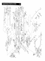
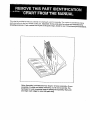
Note: A PART LIST/EXPLODED DRAWING and a PART IDENTIFICATION CHART are attached in the center of
this manual. Remove the PART LIST/EXPLODED DRAWING and the PART IDENTIFICATION CHART before
beginning assembly.
2
3
Thank you for selecting the innovative and versatile
WELDER ° PRO 9930 Home Gym. The WELDER ° PRO
9930 offers a unique selection of weight stations
designed to develop every major muscle group of the
body. Whether your goal is to tone your body, build
dramatic muscle size and strength or improve your
cardiovascular system, the WELDER ° PRO 9930 will
help you to achieve the results you want.
HELPLINE at 1-800-736-6879, Monday through
Saturday, 7 a.m. until 7 p.m. Central Time (excluding
holidays). To help us assist you, please note the product model number and serial number before calling.
The model number is 831.159720. The sedal number
can be found on a decal attached to the WELDER ®
PRO 9930 Home Gym (see the front cover of this
manual).
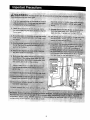
For your benefit, read this manual carefully before
using the WELDER® PRO 9930 Home Gym. If you
have additional questions, please call our toll-free
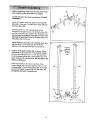
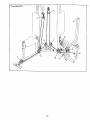
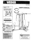
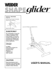
Please use the drawing below to familiarize yourself with the major parts and how they fit together,
Lat Bar
ASSEMBLED
DIMENSIONS:
Height: 78 in.
Width:
65 in.
Depth:
34 in.
High Pulley
Station
Butterfly
Backrest
Backrest
Curl
Adj
Seat
Knob
Low Pulley
Leg Press
Lever
Weight
Stack
Foot Plate
4
Note: This introduction will save you more time
than it takes to read itt
Identifying Parts
To help you identify the small parts used in assembly, we have included a PART IDENTIFICATION
CHART located in the center of this manual. Place
the chart on the floor or work table and use it to
quickly identify different parts for each step. Note:
Some small parts may have been pre-attached for
shipping. If a part is not in the parts bag, check to
see if it has been pre-attached.
Orienting Parts
As you assemble this product, be sure that all parls
are oriented as shown in the drawings.
Tightening Parts
Tighten all parts as you assemble them, unless
instructed to do otherwise.
Some assembly ste_s require two people.
Lining Up the Tools
Assembly requires the following tools (not included):
Giving Yourself a Good Start
Before you begin the assembly process itself, take
the time to complete the steps outlined here.
• Two (2) adjustable wrenches
Clearing the Workspace
Clear a workspace that is large enough to hold all
parts and allow you to walk all the way around the
assembled equipment.
• One (1) standard screwdriver
_=._==,(_
• One (1) phillips screwdriver
• One (1) rubber mallet
Unpacking the Box
To make the assembly process as smooth as possible, we have broken it into separate stages. All parts
used in each stage are found in individual packages
in the shipping box. Place all parts in a cleared area
and remove the packing materials. Do not dispose of
the packing materials until assembly is completed.
• Lubricant, such as grease or petroleum jelly,
and soapy water
• Tape, such as clear tape or masking tape
Assembly will be more convenient if you have a
socket set, a set of open-end or closed-end wrenches
or a set of ratchet wrenches.
Important: Wait until you begin each assembly
stage to open the parts bag labeled for that
assembly stage.
w
The Four Stages
of the Assembly
Process
Frame Assembly
You will begin by assembling the base and the
upright frames that serve as the skeleton of the
equipment.
Cable Assembly
This assembly completes the cables and pulleys
that connect the moving arms with each other and
with the weights.
Arm Assembly
This assembly completes the press and butterfly
arms that you operate while you are exercising.
Seat Assembly
This assembly completes the seat and backrest
that support your body while you are exercising_
5
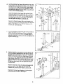
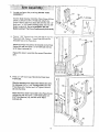
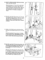
1
1.
38
Before beginning, make sure that you have read
and understood the information on page 5.
19
Locate and open the parts bag labeled "FRAME
ASSEMBLY."
61
Insert four 5/16" x 2 1/2" Carriage
through the indicated holes in the
and the Press Base (60). Note: If
secure them by putting a small
• the head of each Bolt, Place the
Press Base flat on the floor.
Bolts (1) up
Butterfly Base
the Bolts fall
piece of tape
Butterfly Base
(61)
out,
over
and
Attach the Press Base (60) to the Butterfly Base (61)
with two 5/16" x 2 1/2" Botts (3), two 5/16" Flat
Washers (19), and two 5/16" Nylon Locknuts (2).
2.
60
2
Press a 2" Square Inner Cap (38) into the Butterfly
Base (61). Press two 2" Square inner Caps (38) into
the Press Base (60).
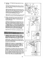
Position the Butterfly Upright (62) as shown. Place
the bracket on the lower end of the Butterfly Upright
(62) over the indicated 5/16" x 2 1/2" Carriage Bolts
(1) in the Butterfly Base (61). Hand tighten two 5/16"
Nylon Locknuts (2) onto the Bolts. Do not tighten the
Nylon Locknuts yet.
Place the bracket on the lower end of the Press
Frame Upright (59) over the indicated 5/16" x 2 1/2"
Carriage Bolts (1) in the Press Base (60). Hand tighten two 5/16" Nylon Locknuts (2) onto the Bolts. Do
not tighten the Nylon Locknuts yet.
6
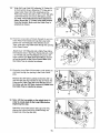
3
38
2
Position
with the
1
" "3.-'Place _vo'_/e!ghi Burn'pers (8_ over'the indicated
holes in the Butterfly Base (61). Slide the Weight
Guides (58) into the indicated holes.
-"
3
58
Attach the Weight Guides (58) to the Butt_;iy Base
(61) with two 3/8" x 2 1/2" Bolts (6), four 3/8" Flat
Washers (17), and two 3/8" Jam Nuts (18).
Pin
Slide the eight Weights (8) onto the Weight Guides
(58). Make sure the Weights are turned so the pin
grooves are on the bottom of the weights.
61
6
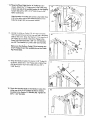
4.
Press a Weight Tube Bumper (76) into tiie lower end
of the Weight Tube (77). Slide the Weight Tube into
the center hole in the Weights (8).
4
Lubricate
Lubricate the holes in the Top Weight (78). Slide the
Top Weight onto the Weight Guides (58).
!!
5°
_
Press a 2" Square Inner Cap (38) into the Butterfly
Top Frame (64). Press two 1" Round Inner Caps (41)
into the top of the Butterfly Top Frame.
°
n
o
38
2
Attach the Butterfly Top Frame (64) to the Press Top
Frame (63) with two 5/16" x 2 1/2" Bolts (3), two 5/16"
Flat Washers (19), and two 5/16" Nylon Locknuts (2).
41
64
63
\
Press a 2" Square Inner Caps (38) into the end of the
Press Top Frame (63).
/38
7
2
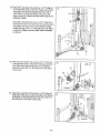
_._ Hold-the Butteflly -Top Frame-(64) and the Press Top
Fr._r:ne(63)-on the indicated brab'kets on" the Uprights
(59, 62) and the Weight Guides (58)• Note: Before
attaching the Top Frames to the Uprights, make
sure that both Weight Guides (58) are positioned
inside of the indicated holes.
6
2O
Attach the Butterfly Top Frame (64) and the Press
Top Frame (63) to the Uprights (59, 62) and Weight
Guides (58) with four 5/16" x 2. 3/4" Bolts (20), two
Top Plates (46), and four 5/16" Nylon Locknuts (2).
Do not tighten the Nylon Locknuts yet.
58--<
Secure the Weight Guides (58) to the Butterfly Top
Frame (64) and to the Press Top Frame (63) with two
3/8" x 2 1/2" Bolts (6), four 3/8" Flat Washers (17),
and two 3/8" Jam Nuts (18).
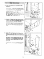
7,
Turn the Seat Brace (75) so the nut is on the side as
shown. Attach the Seat Brace (75) to the Butterfly
Base (61) with the 5/16" x 2 1/2" Carriage Bolts (1)
and two 5/16" Nylon Locknuts (2). Do not tighten the
Nylon Locknuts yet.
-----.
_',
r.
O
_o'1
io
_-_2
_,.__.
59_
62 f
7
61
8.
Hold the Seat Bar (74) between the Seat Brace (75)
and the Butterfly Upright (62) so that the hole that is
closest to the welded plate is facing the Seat Brace.
Attach the Seat Bar (74) to the Seat Brace (75) with
two 5/16" x 2 1/2" Bolts (3), two 5/16" Flat Washers
(19), and two 5/16" Nylon Locknuts (2). Do not overUgten the Bolts or the Curl Post attached in step
38 will not slide freely. Do not tighten the Nylon
Locknuts yet.
Attach the Seat Bar (74) to the Butterfly Upright (62)
with two 5/16" x 2 1/2" Bolts (3), two 5/16" Flat
Washers (19), and two 5/16" Nylon Locknuts (2).
Important: Go back and tighten all of the Nylon
Locknuts used in steps 1 through 8.
8
Hole
74 /
ii 6ii
/_]
}'l
] o_._3
" / !
'1°
9_
Locate and open the pg,,Is bag labeled "ARM
ASSEMBLY."
3O
See the inset drawing. Orient the Press Frame (53) as
shown. Lubricate a 3/8" x 8" Bolt (30). Attach the
Press Frame to the Press Base (60) with the 3/8" x 8"
Bolt, two 1" x 7/8" Plastic Bushings (29), and one 3/8"
Nylon Locknut (4). Do not overtighten the 3/8"
Nylon Looknut. The Press Frame must pivot easily.
Lubricate
iO. Press a 1 3/4" Square Inner Cap (37} into the top of a
Press Arm (54). Press a 1" Inner Cap (80) into the
indicated hole in the Press Arm.
Attach the Press Arm (54) to the bracket on the Press
Frame (53) with two 5/16" x 2 1/2" Bolts (3) and two
5/16" Nylon Locknuts (2).
Repeat this step to assemble the second Press Arm
(54).
11. Press a I 1/2" Inner Cap (79) into the Press Seat
Frame (52).
Slide the bracket on the Press Seat Frame (52) onto
the indicated 5/16" x 2 1/2" Carriage Bolts (1) in the
Press Base (60). Tighten two 5/16" Nylon Locknuts
(2) onto the Bolts.
79
Attach the Press Seat Frame (52) to the Press Frame
Upright (59) with two 5/16" x 2 3/4" Bolts (20), two
5/16" Flat Washers (19), and two 5/16" Nylon
Locknuts (2).
6O
9
_12. PreS's-two.1 1/2_' SqeaFe Irme_ Caps-(79) into the Eeg _ "
Le_,er (49), Insert a Bumper (33) between the brackets on the Leg
Lever (49). Secure the Bumper to the Leg Lever with a
#10 x 1" Screw (32).
Slide the bracket on the Leg Lever (49) onto the Press
Seat Frame (52). Attach the Leg Lever to the Press Seat
Frame with a 5/16" x 2 1/4" Bert (81) and a 5/16" Jam
Nut (90). Do not overtighten the 5116" Jam Nut. It
must be easy for the Leg Lever to pivot.
Attach a 3/8" x 2 1/2" Eye Bolt (B3) to the Leg Lever (49)
with a 3/8" Flat Washer (17) and a 3/8" Nylon Locknut
13. Press a 1 3/4" Square Inner Cap (37) into each end of
• the Right Butterfly Arm (68). Wet the lower end of the
Arm with soapy water. Slide a 10" Pad (65) onto the
lower end of the Arm.
Lubdcate the indicated axle on the Butterfly Top Frame
(64). Orient the Right Butterfly Arm (68) as shown and
slide it onto the axle. Secure the Butterfly Arm with two
1" Retainers (25) and a 1" Round Cap (26). Note: Place
the Retainer Rings on top of the inverted Round Cap
and gently tap the Cap onto the axle with a hammer,
Make sure the teeth on the Retainer Rings bend
towards the Cap as shown in the inset drawing.
Repeat this step to assemble the Left Butterfly Arm (67).
14. Locate and open the parts bag labeled "CABLE
ASSEMBLY AND PULLEYS." For Cable Identification
and routing during steps 14 to 32, refer to the Cable
Diagrams and Cable ID Chart on pages 19 and 20.
Insert two 3/8" x 1" Bolts (15) into the welded brackets
on the Left and Right Butterfly Arms (67, 68), Secure the
Bolts with a 3/8" Jam Nut (18).
Identify the Short Cable (71). It is approximately 74 1/2"
long and it has a closed loop on each end. Slide one
end of the cable onto each of the 3/8" x 1" Bolts (15).
Secure the Cable to the Bolts with 3/8" Jam Nuts (18).
Do not overtighten the Nylon Jam Nuts.
Remove both 3 1/2" Pulleys (5) from the pre-assembled
Adjustable Pulley Plates (44). Wrap the Short Cable (71)
around a 3 1/2" Pulley (5) in the direction shown. Attach
the 3 1/2" Pulley and a Cable Trap (39) to the top hole in
the two Adjustable Pulley Plates (44) with a 3/8" x 2" Bolt
(35) and a 3/8" Nylon Locknut (4). Make sure the Cable
Trap and Pulley Plates are oriented as shown.
10
15. Wrap the Short Cable over a "V" Pulley'(21) as _-,
shown. Attach the "V" Pulley and a Long Cable Trap
(14) to one side of the welded bracket on the Butterfly
Upright (62) with a 3/8" x 2 1/2" Bolt (6) and a 3/8"
Nylon Locknut (4).
15
Attach another "V_ Pulley (21) and a Long Cabte Trap
(14) to the other side of the welded bracket on the
Butterfly Upright (62) in the same manner.
Bracket
16. Identify the Medium Cable (72). It is approximately
140" long and it has a ball on one end and a threaded
shaft on the other. Wrap the Medium Cable over the 3
1/2" Pulley (5), as shown. Attach the Pulley to the
Press Top Frame (63) with a 3/8" x 3 1/2" Bolt (24),
one 3/8" Flat Washer (17), and a 3/8" Jam Nut (18).
16
63
24
Make sure the Medium Cable (72) is between the
3 1/2" Pulley (5) and the welded pin on the Press
Top Frame (63).
Pin
17
17. Wrap the Medium Cable (72) over a 3 1/2" Pulley (5)
as shown. Attach the 3 1/2" Pulley and a Cable Trap
(39) to the Press Top Frame (63) with one 3/8" x
3 3/4" Bolt (7).
17
5
39
63
18. Route the threaded shaft on the Medium Cable (72)
under one of the 3 1/2" Pulleys (5) that is already
mounted in the Double =U" Bracket (36). Tighten the
3/8" x 1 3/4" Bolt (22).
18
7
11
22
_19. Wra{:):the Mediur_Cable (72)-over a 4 1/2" Pulley -.
(34) in the c]irection shown. Atta'¢h the Pulley to the
Butterfly Top Frame (64) with a 3/8" x 1 3/4" Bolt (22)
and a 3/8" Nylon Locknut (4).
20. Attach the threaded shaft on the Medium Cable (72)
to the Small "U"-Bracket (43) with a 1/4" Flat Washer
(11) and a 1/4" Nylon Locknut (16). Note: See the
inset drawing. Do not completely tighten the
Nylon Locknut; it should be threaded only two
turns onto the end of the Cable.
Attach the Small "U"-Bracket (43) to the hole in the
Weight Tube (77) with a 5/16" x 1 3/4" Bolt (9), and a
5/16" Nylon Locknut (2).
21. Identify the Long Cable (73). It is approximately
299.25" long and it has a ball on one end and a loop
on the other. Route the end with the loop through the
slot in the cable guide on the Butterfly Base (61).
-21
Route the Long Cable (73) under a 3 1/2" Pulley (5)
as shown• Attach the Pulley and a Cable Trap (39) to
the indicated bracket on the Butterfly Base (61) with a
3/8' x 2" Bolt (35) and a 3/6" Nylon Locknut (4). Make
sure the Cable Trap is oriented as shown.
73
12
39
-22._Wrap the'Long(_able'i73)'aro_nd
a 3 t/2" Pulley (5) ....
in the direction shown. Attach the Pulley and a Cable
Trap (39) to the Butterfly Upright (62) with a 3/8" x
3 3/4" Bolt (7), a 3/8" Flat Washer (17) and a 3/8"
Nylon Locknut (4). Make sure the Cable Trap is oriented as shown.
22
35
Wrap the Long Cable (73) over a 3 1/2" Pulley (5) in
the direction shown. Re-attach the Pulley and a Cable
Trap (39) to the lower hole in the Adjustable Pulley
Plates (44) with a 3/8" x 2" Bolt (35) and a 3/8" Nylon
Locknut (4). Make sure the Cable Trap is oriented
as shown.
23. Wrap the Long Cable (73) around a 3 1/2" Pulley (5)
in the direction shown. Attach the Pulley and a Cable
Trap (39) to the indicated bracket on the Butterfly
Base (61) with a 3/8" x 2" Bolt (35) and a 3/8" Nylon
Locknut (4).
23
24. Wrap the Long Cable (73) around a 3 112" Pulley (5).
Attach the Pulley and a Cable Trap (39) to the indicated bracket on the Butterfly Base (61) with a 3/8" x 2"
Bolt (35) and a 3/8" Nylon Locknut (4).
24
35
4
61
13
Bracket
*25. Notd:.For.clarity,:thisand_he
sh_w someparts removed,
following drawings
";
25 - ""~:"
Remove the lower 3 1/2" Pulley (5) from the Double
"U" Bracket (36). Then, wrap the Long Cable (73)
over the Pulley (5) in the direction shown. Attach the
Pulley to the Double "U" Bracket (36) with a 3/8" x 1
3/4" Bolt (22) and a 3/8" Nylon Locknut (4). Make
sure the Double "U" Bracket is oriented as
shown.
26. Wrap the Lollg Cable (73) around a 3 1/2" Pulley (5)
in the direction shown. Attach the Pulley and a Cable
Trap (39) to the indicated bracket on the Press Base
(60) with a 3/8" x 2" Bolt (35) and a 3/8" Nylon
Locknut (4). Make sure the Cable Trap is oriented
as shown.
I
F 73
5
27. Attach a 3 1/2" Pulley (5) and a Cable Trap (39) to
the Press Frame Upright (59) with a 3/8" x 4 3/4" Bolt
(23).
Wrap the Long Cable (73) around the 3 1/2" Pulley
(5) in the direction shown. Hand tighten a 3/8" Nylon
Locknut (4) two turns onto the 3/8" x 4 3/4" Bolt. In
step 31, another Pulley will be attached to the Bolt.
\4
28. Route the Long Cable (73) through the opening in the
Press Frame (63) and wrap the Long Cable around a
3 1/2" Pulley (5) in the direction shown. Then, route
the Long Cable back through the opening in the
Press Frame.
38
Attach the 3 1/2" Pulley (5) and a Cable Trap (39) to
the indicated hole in the Press Frame (53) with a 3/8"
x 3 1/4" Bolt (26), a 3/8" Flat Washer (17), and a 3/8"
Nylon Locknut (4). Make sure the Pulley is mounted on the inside of the Press Frame (53). Make
sure the Cable Trap is oriented as shown.
14
" 29-.'" wrap tl_e"Lon_) Cable" (73") around a:=V"-Pulley_21) ....
in the direction shown. Attach the "V"-Pulley and a
Large Cable Trap (14) to the small tube on the
Press Seat Frame (52) with a 3/8" x 3 1/4" Bolt (28),
a 3/8" Flat Washer (17) and a 3/8" Nylon Locknut
(4). Note: The small tube has three adjustment
holes. Mount the "V"-Pulley in the hole farthest
from the Upright. Make sure the Cable Trap is
oriented as shown.
4
73
30. Route the Long Cable (73) back through the opening
in the Press Frame (53) and wrap the Long Cable
around a 3 1/2" Pulley (5) in the direction shown.
Then, route the Long Cable back through the opening
in the Press Frame.
Attach the 3 1/2" Polley (5) and a Cable Trap (39) to
the indicated hole in the Press Frame (53) with a 3/8"
x 3 1/4" Bolt (28), 3/8" Flat Washer (17), and a 3/8"
Nylon Locknut (4). Make sure the Pulley is mounted on the inside of the Press Frame. Make sure
the Cable Trap is oriented as shown.
31. Route the Long Cable (73) around a 3 1/2" Pulley (5)
and back through the opening in the Press Frame
(53).
31
Remove the 3/8" Nylon Locknut (4) from the 3/8" x 4
3/4" Bolt (23) that was inserted in step 27. Attach the
Pulley and a Cable Trap (39) to the Bolt and secure
the Pulley with the 3/8" Nylon Locknut (4). Make sure
the Cable Trap is oriented as shown.
_(_----5
23_
/
73
32. Note: Lift the top weight on the weight stack in
order to create slack in the Long Cable before
beginning this step.
32
Attach the Long Cable (73) to the Leg Lever (49),
slipping the looped end of the Cable through the
looped end of the Eye Bolt (83).
15
p_
.................
...........
o_ atA
.............................
i!iiiiiiii!iiiiiiiiiiiiiii!ili::!ili!!iii_iiii!ii!i_iiii!iiiiiiiil
i
iii!: semb,y
_
ii!i_!ili:iriiii!i!iiiiiiiii!ili_ili_i!iii_i:_i_iii!ii;ili:i!ii!!iiiilililill
.
.
_::
,#:_ ...................
_
...............................
: .............................
m: m ......................................................
51
33. Locateandopenthepa:tsbaglabeled"SEAT
ASSEMBLY."
Insert a 1/4" x 2" Carriage Bolt (85) through the center hole in a Seat Plate (42). Attach the Seat Plate to
a Seat (51) with two 1/4" x 3/4" Screws (13).
85
11
-42
Insert the 1/4" x 2" Carriage Bolt (85) into the indicated hole in the Press Seat Frame (52) and secure it
with a 1/4" Flat Washer (11) and a 1/4" Nylon Locknut
(16). Secure the other end of the Seat (51) with a 1/4"
x 2" Bolt (86) and a 1/4" Fiat Washer (11).
34. Press four 3/4" Round Inner Caps (40) into the ends
of the Pad Tubes (48) and the indicated tubes on the
Leg Lever (49) and the Press Seat Frame (52).
52
34
4O
Insert the Pad Tubes (48) into the indicated holes in
the Leg Lever (49) and the Press Seat Frame (52).
Slide Foam Pads (47) onto the ends of the Pad
Tubes.
35. Insert a 1/4" x 2 1/2" Cardage Bolt (12) through the
center hole in a Seat Plate (42). Attach the Seat Plate
to the Press Backrest (89) with two 1/4" x 314" Screws
(13).
89
Insert the 1/4" x 2 1/2" Cardage Bolt (12) with a 1/4"
Flat Washer (11) into the indicated hole in the Press
Frame Upright (59) and secure it with a 1/4" Nylon
Locknut (16).
Secure the other end of the Press Backrest (89) with
a 114"x 2 112" Screw (10) and a t/4" Flat Washer
bl).
16
42
" "36__nsert a :1/_,
';"x 1-1/2" (_'arfiage'Bolt (82) "througlTthe_ "-"
center hole in a Seat Plate (42). Attach the Seat Plate
to a Seat (51) with two 1/4" x 3/4" Screws (13).
51
\
Insert the 1/4" x 1 1/2" Carriage Bolt (82) into the indicated hole in the Seat Bar (74) and secure it with a
1/4" Flat Washer (11) and a 1/4" Nylon Locknut (16).
Secure the other end of the Seat (51) with a 1/4" x
1 1/2" Screw (68) and a 1/4" Flat Washer (11).
42
74
88
37. Attach the Backrest (66) to the indicated holes in the
Butterfly Upright (62) with two 1/4" x 2 1/2" Screws
(10) and two 1/4" Flat Washers (11).
37
66
38. Attach the Curl Pad (69) to the Curl Post (70) with two
1/4" x 3/4" Screws (13).
Insert the Curl Post (70) into the Seat Brace (75) and
secure the Curl Post at the desired height with the
Adjustment Knob (45).
17
38
69
7O
1_9. Appl_,.{he WELDER PRO 992,0 decal in the locationshown.
";
39"
WELDER
PRO 9930
40. Make sure that all parts have been properly tightened.
ADJUSTMENT, beginning on page 21 of this manual.
The use of the remaining parts will be explained in
Before using the home gym, pull each cable a few times to make sure that the cables move smoothly over
the pulleys. If one of the cables does not move smoothly, find and correct the problem. IMPORTANT: If the
cables are not properly installed, they may be damaged when heavy weight is used. If there is any
slack in the cables, you will need to remove the slack by tightening the cables. See TROUBLESHOOTING AND MAINTENANCE on page 22.
18
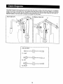
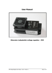
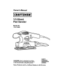
The Cable Diagrams below and on the next page show the proper routing of the Short Cable (71), the Medium
Cable (72), and the Long Cable (73). The numbers show the correct route for each Cable. Make sure that the
Cables are routed correctly, that the Pulleys move smoothly, and that the Cable Traps do not touch or
bind the Cables. Incorrect cable routing can damage the home gym.
Short Cable (71)
I Medium Cable (72)
Cable ID Chart
71, 74.50"
72, 140"
73, 299.25"
19
2
,--4
Long Cable; (73)
10
7
2
12
2O
_
=
The instructions below describe how each part of the home gym can be adjusted. Refer to the exercise poster
accompanying this manual to see how the home gym should be set up for each exercise. IMPORTANT: When
using an attachment, make sure it is in the correct starting position for the exercise to be performed. If
there Is any slack in the cables or chain as an exercise is performed, the effectiveness of the exercise
will be reduced.
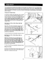
Changing the Weight Setting
To change the setting of the weight stack, insert a Weight
Pin (87) under the desired Weight (8), Make sure you
insert the Weight Pin as far as it will go. Note: Due to the
cables and pulteys, the amount of resistance at each
exercise station may vary from the weight setting.
Use the WEIGHT RESISTANCE CHART on page 23 to
find the approximate amount of resistance at each
weight station.
67
Attaching the Lat Bar-or Nylon Strap to the High
Pulley Station
56
Attach the Lat Bar (50) to the Medium Cable (72) with a
Cable Clip (57). For some exercises, the Chain (55)
should be attached between the Lat Bar and the Medium
Cable with two Cable Clips. Adjust the length of the
Chain between the Lat Bar and the Medium Cable so
the Lat Bar is in the correct starting position for the
exercise to be performed.
The Nylon Strap (56) can be attached in the same manner,
Attaching the Lat Bar or Nylon Strap to the Low
Pulley Station
Attach the [_at Bar (50) to the Long Cable (73) with a
Cable Clip (57). For some exercises, the Chain (55)
should be attached between the Lat Bar and the Long
Cable with two Cable Clips. Adjust the length of the
Chain between the Lat Bar and the Long Pulley Cable
so the Lat Bar is in the correct starting position for
the exercise to be performed.
The Nylon Strap (56) can be attached in the same manner,
Using the Curl Pad
To use the Curl Pad (69), insert the Curl Post (70) into the
Seat Brace (75) and secure the Curl Post atthe desired
height with the Adjustment Knob (45).
21
55
o
.
Inspect and tighten all parts each time you use the home gym. Replace any worn parts immediately.
The
home gym can be cleaned using a damp cloth and mild non-abrasive detergent. Do not use solvents.
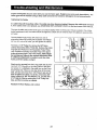
Tightening the Cables
If a cable slips off the pulleys often, the cable may have become twisted. Remove the cable and re-install
it. If the cables need to be replaced, see ORDERING REPLACEMENT PARTS on the back cover of this manual.
The type of cable used on the home gym can stretch slightly when it is first used. If there is slack in the cables
before resistance is felt, the cables should be tightened. Slack can be removed from the cables in several different ways:
The Adjustable Pulley Plates (44) have two sets of
adjustment holes. By moving one or both 3 1/2" Pulleys
(5) to a di,flerent set of holes, you win tighten the cables.
To move a 3 1/2" Pulley (5), remove the 3/8" Nylon
Locknut (4) and the 3/8"x 2" Bolt (35). Remove the Cable
Trap (39) and Pulley from the Adjustable Pulley Plates
(44). Re-attach the Pulley and Cable Trap to the appropriate adjustment hole in the Pulley Plates. Note: Begin
by moving one Pulley to the second adjustment hole.
If additional adjustment is needed, move the other
Pulley until the cables are tight,
Slack can be removed from the Long Cable (73) by moving the 3 1/2" Pulley (5) on the Long Cable in the direction shown. It is attached to the small tube on the Press
Seat Frame (52). There are two free holes in the small
tube, and you can move the 3 1/2" Pulley to any one of
them to tighten the cables. To do this, remove the 3/8"
Nylon Locknut (4), 3/8" Flat Washer (17), and the 3/8" x
2 1/2" Bolt (6). Start by moving the 3 1/2" Pulley one
hole, and then one more as needed.
Reattach the Bolt, Washer, and Locknut.
22
The threaded shaft on the Med urn'Cab e (72) attached to-.
the Weights (8) can also be used to tighten the cables.
_
(3./
_ - --72
To tighten the Medium Cable (72), remove the Small "U"Bracket (43) by removing the 5/16" Nylon Locknut (2) and
the 5/16" x 1 3/4" Bolt (9).
See the inset drawing. Tighten the 1/4" Nylon Locknut
(16) at the end of the Medium Cable (72) as far as it will
go. Then re-attach the Small "U"-Bracket (43).
_i,-..---2
043
I
I
/
J
/
72_
i iI iNl
43_-
The chart below shows the approximate weight resistance at each exercise station. "Top" refers to the 6 lb. top
weight; the other numbers refer to the 12.5 lb. weight plates. Note: The actual resistance at each station may
vary due to differences in individual weight plates as well as friction between the cables, pulleys, and
weight guides.
23
Key No.
Qty.
Description
Key No.
Qty.
Description
1
2
3
8
27
12
5/16" x 2 1/2" Carriage Bolt
5116" Nylon Locknut
5/16" x 2 112" Bolt
49
50
51
1
1
2
Leg Lever
Lat Bar
Seat
4
5
6
7
8
9
10
11
12
• 13
14
15
16
17
18
19
20
17
15
6
2
8
1
3
9
1
8
3
2
4
14
9
10
6
3/8" Nylon Locknut
3 1/2" Pulley .
3/8" x 2 1/2" Bolt
3/8" x 3 3/4" Bolt
Weight
5/16" x 1 3/4" Bolt
1/4" x 2 1/2" Screw
1/4" Flat Washer
1/4" x 2 1/2" Carriage Bolt
1/4" x 3/4" Screw
Long Cable Trap
3/8" x 1" Bolt
1/4" Nylon Locknut
3/8" Flat Washer
3/8" Jam Nut
5/16" Flat Washer
5/16" x 2 3/4" Bolt
52
53
54
55
56
57
58
59
60
61
62
63
64
65
66
67
68
1
1
2
1
1
4
2
1
1
1
1
1
1
2
1
1
1
Press Seat Frame
Press Frame
Press Arm
Chain
Nylon Strap
Cable Clip
Weight Guide
Press Frame U;._ight
Press Base
Butterfly Base
Butterfly Upright
Press Top Frame
Butterfly Top Frame
10" Pad
Backrest
Left Butterfly Arm
Right Butterfly Arm
21
22
23
24
25
26
27
28
29
30
31
32
33
34
35
36
37
38
39
40
41
42
43
44
45
46
47
48
3
3
1
1
4
2
2
3
2
1
4
1
1
1
6
1
6
6
12
4
2
3
1
2
1
2
4
2
_ Pulley
3/8" x 1 3/4" Bolt
3/8" x 4 3/4" Bolt
3/8" x 3 1/2" Bert
1" Retainer
1" Round Cap
1 1/8" x 2 1/2" Plastic Bushing
3/8" x 3 114" Bolt
1" x 7/8" Plastic Bushing
3/8" x 8" Bolt
Hand Grip
#10 x 1" Screw
Bumper
4 112"Pulley
3/8" x 2" Bolt
Double "U" Bracket
1 3/4" Square Inner Cap
2" Square Inner Cap
Cable Trap
3/4" Round Inner Cap
1" Round Inner Cap
Seat Plate
Small "U" Bracket
Adjustable Pulley Plate
Adjustment Knob
Top Plate
Foam Pad
Pad Tube
69
70
71
72
73
74
75
76
77
78
79
80
81
82
83
84
85
85
87
88
89
90
#
#
1
1
1
1
1
1
1
1
1
1
3
2
1
1
1
2
1
1
1
1
1
1
1
1
Curl Pad
Curl Post
Short Cable
Medium Cable
Long Cable
Seat Bar
Seat Brace
Weight Tube Bumper
Weight Tube
Top Weight
1 112"Square Inner Cap
1" Inner Cap
5/16" x 2 1/4" Bolt
1/4" x 1 1/2" Carriage Bolt
3/8" x 2 1/2" Eye Bolt
Weight Bumper
1/4" x 2" Carriage Bolt
1/4" x 2" Bolt
Weight Pin
1/4" x 1 1/2" Screw
Press Backrest
5/16" Jam Nut
User's Manual
Exercise Poster
Note: "#" indicates a non-illustrated
part. Specifications
Note: "#" indicates a non-illustrated part. Specifications
are subject to change without notice.
are subject to change without notice.
38
39
31
2(
19
64
5
-41--e
6
14
13
5
2
65
7
._- 40
42
12
47
51
5
23
5
8O
11
4
8O
35
61
38
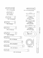
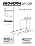
Thischartis providedtohelpyouidentifythesmallpartsusedin assembly.
Thenumberin parenthesis
below
eachpartrefers to the key number of the part. Important: Some parts may have been pre-assembled for
shipping
purposes.
If you cannot
find a part in the parts bags, check to see if it has been pre-assemblecl.
Note: Assembly is divided into four stages: 1) frame assembly; 2) arm
assembly; 3) cable and pulley assembly; and 4) seat assembly. The
hardware for each assembly stage is packaged separately. Wait until
you begin each stage to open that parts bag.
1/4" Flat Washer (11)
5/16" x 1 3/4" Bolt (9)
5/16" x 2 1/2" Bolt (3)
I
5/16" Flat Washer (19)
5/16" x 2 3/4" Bolt (20)
'1 3/8" Flat Washer
(17)
114" Nylon Locknut (I 6)
1/4" x 2" Bolt (86)
5/16" Nylon Locknut (2)
1/4" x 2" Carriage
Belt (85)
5/16" Jam Nut (90)
1/4" x 2 1/2" Carriage
Bolt (12)
3/8" Nylon Locknut (4)
<_X\\\\\\\\\\\I'_
#10 x 1" Screw (32)
3/8" Jam Nut (18)
1/4" x 3/4" Screw (13)
318" x 2 I/2" Eye Bolt (83)
1/4" x 2 1/2" Screw (10)
_\\\\\\\\\\\_
_\\\\\\\\\\\\_
1/4" x 1 1/2" Screw (88)
1/4" x 1 1/2" Carriage Bolt (82)
3/8" x 1" Belt (15)
I
"V" Pulley (21)
(Not shown to scale)
3/8" x 1 3/4" Bolt (22)
3 1/2" Pulley (5)
(Not shown to scale)
3/8" x 2" Bolt (35)
r-,=_=h
_\\\\\\\1
4 1/2" Pulley (34)
(Not shown to scale)
3/8" x 2 1/4" Bolt (81)
o
m
x
3/8" x 2 1/2" Bolt (6)
%\\\\\
3/8" x 3 1/4" Bolt (28)
&\\\\\\\]
3/8" x 3 1/2" Bolt (24)
(_\\\\\\\1
1" Retainer (25)
3/8" x 3 3/4" Bolt (7)
&\\\\\\\}
3/8" x 4 3/4" Bolt (23)
3/4" Round Inner Cap (40)
1" x 7/8" Plastic
Bushing
(29)
1" Round Cap (26)
1" Round
Inner Cap (41)
1" Inner Cap (80)
1 3/4" Square
1 1/2" Square
Inner Cap (37)
Inner Cap (79)
J
2" Square
Inner Cap (38)
SmARsThe model number and senat number of your WELDER ® PRO
9930 Home Gym are hsted on a decal attached to the frame See
the front cover of th_s manual to find the Iocatron of the decal
Model No. 831.159720
QUESTIONS?
If you find that:
• you need help assembling or
operating the WELDER ®PRO 9930
Home Gym
• a part is missing
• or you need to schedule repair
service
A_I replacement parts are ava=lable for tmmed_ate purchase or
special order when you visit your nearest SEARS Service Center,
To request service or to order parts by telephone, call the toll-free
numbers hsted at the left
When requesting help or service, or ordenng parts, pleasp be prepare_" to provJde l',_ foli,t,w_ng _rlformat_:,-,
• The MODEL NUMBER of the product (831.159720)
• The NAME of the product (WELDER ®PRO 9930 Home Gym)
call our toll-free HELPLINE
1-800-736-6879
Monday-Saturday, 7 am-7 pm
Central Time (excluding holidays)
• The KEY NUMBER and DESCRIPTION of the PART (see the
PART LIST/EXPLODED DRAWING in the center of thrs manual).
SEARS, ROEBUCK AND CO., HOFFMAN ESTATES, IL 60179
ORDERING REPLACEMENT PARTS
If parts become worn and need to
be replaced, call the following tollfree number
1-800-FON-PART
(1-800-366-7278)
[
FULL 90 DAY WARRANTY
I
For 90 days from the date of purchase, if failure occurs due to defect in matenal or workmanship in this
SEARS WEIGHT SYSTEM EXERCISER, cOntact the nearest SEARS Service Center throughout the
United States and SEARS will repa=r or replace the WEIGHT SYSTEM EXERCISER, free of charge.
This warranty does not apply when the WEIGHT SYSTEM EXERCISER is used commerctally or for
rental purposes.
Th_s warranty gtves you spec=fic legal rights, and you may also have other rights which vary from state
to state
SEARS, ROEBUCK AND CO., DEPT. 817WA, HOFFMAN ESTATES, IL 60179
Part No. 158932 R0999B
Pnnted Jn Canada © 1999 Sears, Roebuck and Co