1
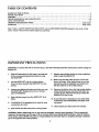
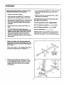
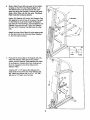
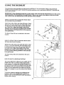
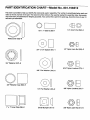
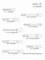
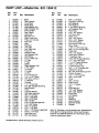
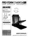
USER'S MANUAL
Model No. 831.159412
Serial No.
Write the serial number in the
space above for reference.
Serial Number Decal
F-
x
EE R
C
i _%_E_
EQUIPMENT
HELPLINE!
1-800-735-5879
CAUTION!
Read all precautions and
Instructions
in this user's manual before using this equipment. Save this user's manual
for future reference.
PATENT PENDING
SEARS, ROEBUCK AND CO., HOFFMAN ESTATES, IL 60179
TABLE OF CONTENTS
IMPORTANT
PRECAUTIONS
.....................................................................
BEFORE YOU BEGIN ...........................................................................
ASSEMBLY ....................................................................................
TROUBLE-SHOOTING
AND MAINTENANCE
.......................................................
USING THE BODYLIFT .........................................................................
ORDERING REPLACEMENT PARTS ......................................................
2
3
4
10
11
Back Cover
WARRANTY
Back Cover
.........................................................................
Note: There is a PART IDENTIFICATION CHART and an EXPLODED DRAWING stapled to the center of this
user's manual. Remove them before beginning assembly.
IMPORTANT
PRECAUTIONS
WARNING: To reduce the risk of serious injury, read the following important precautions before using the
BODYMFT.
.
Read all instructions in this user's manual and
in the accompanying literature before using
the BODYLIFT.
7. Always wear athletic shoes for foot protection
when using the BODYLIFT.
Make sure that the cable remains on the pulleys at all times. If the cable binds as you are
exercising, stop immediately and make sure
that the cable is on all of the pulleys.
8.
.
Use the BODYLIFT only on a level surface.
Cover the floor beneath the BODYLIFT for protection.
Inspect and tighten all parts each time you use
the BODYLIFT. Replace any worn or frayed
parts immediately.
3.
o
.
Keep children away from the BODYLIFT at all
times.
5.
The BODYLIFT is designed to be used by only
one person at a time.
6.
Keep hands end feet away from moving parts.
Remove the lat bar from the high pulley station
when performing any exercise that does not
use the lat bar. Remove the lat bar when the
BODYLIFT is not in use.
10. If you feel pain or dizziness at any time while
exercising, stop immediately and begin cooling down.
11. Never place your feet under the footrest.
WARNING: Before beginning this or any exercise program, consult your physician. This is especially
important for persons over the age of 35 or persons with pre-existing health problems. Read all instructions before using. SEARS assumes no responsibility for personal injury or property damage sustained
by or through the use of this product.
2
BEFORE YOU
BEGIN
Thank you for selecting the PROFORtvP BODYLIFT
Body Weight Resistance System. The compact
BODYLIFT features an impressive array of weight stations designed to develop every major muscle group
of the body. Whether your goal is a shapely figure,
dramatic muscle size and strength, or a healthier cardiovascular system, the BODYLIFT will help you to
achieve the specific results you want.
Department toil-free at 1-800-736*6879, Monday
through Saturday, 7 a.m. until 7 p.m. Central Time
(excluding holidays). To help us assist you, please
note the product model number and serial number
before calling. The model number is 831.159412. The
serial number can be found on a decal attached to
the BODYLIFT (see the front cover of this user's manual).
For your benefit, read this user's manual carefully
before using the BODYLIFT. If you have additional
questions, please call our Customer Service
Before reading further, please look at the drawing
below and familiarize yourself with the parts that are
labeled.
Assembled Dimensions:
Lat Bar
Height: 90 in. (Extended)
Width: 38 in.
Length: 51 in.
High Pulley Station
Note: The BODYLIFT
requires a minimum
ceiling height of 7 1/2
feet.
Arms
Backrest
Press Arms
Seat
Leg Lever
Low Pulley Station
Base
Footmst
3
ASSEMBLY
Before beginning assembly, carefully read the
following Information end Instructions:
• As you assemble the BODYLIFT, make sure that
all parts are oriented exactly as shown in the
drawings.
• Assembly requires two people.
• Tighten all parts as you assemble them, unless
instructed to do otherwise.
• Due to the size of the BODYLIFT, it should be
assembled in the location where it will be used.
THE FOLLOWING TOOLS (NOT INCLUDED) ARE
REQUIRED FOR ASSEMBLY:
• Place all parts of the BODYLIFT in a cleared area
and remove the packing materials; do not dispose of the packing materials until assembly is
completed.
Two (2) adjustable wrenches
One (1) standard screwddver
• Read through each assembly step before you
begin.
One (1) phillips screwdriver
• For help identifyingthe small pads used in
assembly, remove the PART IDENTIFICATION
CHART from the center of this user's manual.
Note: Some small parts may have been preattached for shipping purposes. If a part is not
found in the parts bag, check to see if it has been
pre-attached.
.
One (1) rubber mallet
Assembly will be more convenient if you have the
following tools: A socket set, a set of open-end or
closed-end wrenches, or a set of ratchet wrenches.
Before you begin, read the information and
Instructions at the top of this page. Note: The
BODYLIFT requires a minimum ceiling height
of 7 1/2 feet.
Insert the four 3/8" x 2 1/2" Carriage Bolts (70) up
through the indicated holes in the Base (1).
70
Insert These
Carriage
Bolts First
70
,
Slide the Rear Upright (2) onto the four 3/8" x
2 1/2" Carriage Bolts (70) in the Base (1). Make
sure that the Rear Upright is turned as shown.
Tighten a 3/8" Nylon Jam Nut (41) onto each
Carriage Bolt.
2
4
Attach the Footrest (35) to the Front Upright (7)
with two 3/8" x 2 3/4" Bolts (85), two 3/8" Flat
Washers (53), and two 3/8" Nylon Locknuts (33)
as shown.
3.
3
35
85
Remove the 3/8" x I 112"Carriage Bolt (80) and
the 3/8" Nylon Jam Nut (41) from the indicated
brackets on the Front Upright (7). Remove the
loop of Cable (25) from the brackets.
.
53
4
19
41
Lubricate the 3/8" x 1 1/2" Carriage Bolt (80).
Attach the Selector Plate (19) to the brackets on
the Front Upright (7) with the Carriage Bolt and the
3/8" Nylon Jam Nut (41).
.
With the help of a second person, hold the Front
Upright (7) in front of the Rear Upright (2), with the
Selector Plate (19) between the sides of the Rear
Upright.
57
7
Axle
Insert the loopofCable (25) through the sides of
the Rear Upright (2).
Slide a Weld Cover (63) onto each of the indicated axles on the Front and Rear Uprights (7, 2).
The Weld Covers must be turned so the open
sides are facing the Uprights. Lubricate the axles.
Slide a Long Riser (3) onto the axles. The Long
Riser must be turned as shown.
Hold a 3/4" Retainer (57) and a 3/4" Retainer Cap
(59) against the end of one of the axles. The teeth
on the Retainer must bend toward the Retainer
Cap (see the inset drawing). Tap the Retainer and
Retainer Cap onto the axle. Tap a 3/4" Retainer
(57) and a 3/4" Retainer Cap (59) onto the other
axle.
Attach the other Long Riser (3) to the lower axles
on the other side of the Front and Rear Uprights
(7, 2) in the same manner.
cate
5
59
Teeth
.
Slide a Weld Cover (63) onto each of the indicated axles on the Front and Rear Uprights (7, 2).
The Weld Covers must be tumed so the open
sides are facing the Uprights. Lubricate the axles.
Slide a Short Riser (4) onto the axles, The Short
Riser must be turned as shown.
2
Lubricate
Hold a 3/4" J=tetainer (57) and a 3/4" Retainer Cap
(59) against the end of one of the axles. The teeth
on the Retainer must bend toward the Retainer
Cap (see the inset drawing). Tap the Retainer and
Retainer Cap onto the axle. Tap a 3/4" Retainer
(57) and a 3/4" Retainer Cap (59) onto the other
axle.
Attach the other Short Riser (4) to the upper axles
on the other side of the Front and Rear Uprights
(7, 2) in the same manner.
57
Axle
7o
Pull back the Knob (39) on the Selector (20, 26).
Raise the Selector Plate (19) to the position
shown, with the Selector Plate between the sides
of the Selector. Release the Knob, making sure
that it is engaged in one of the holes in the
Selector Plate.
Hold the 3/4" x 1/2" Spacer (64) between the
small holes in the lower end of the Selector (20,
26). Attach the Spacer with a 1/4" x 1 1/4" Bolt
(49) and a 1/4" Nylon Jam Nut (55).
6
59
Teeth
Carefully cut the wire tie attached to the Cable
(25). Wrap the loop of Cable from steps 4 and 5
around the 3 1/2" Pulley (27) as shown. Hold the
Pulley and the Pulley Covers (88) between the
indicated holes in the Selector Plate (19). Make
sure that the Pulley Covers are turned so the
small rims are inside the loop of Cable as shown.
See assembly step 9, and make sure that the
Cable is routed exactly as shown.
Attach the Pulley Covers (88) and the 3 1/2"
Pulley (27) to the Selector Plate (19) with the 3/8"
x 2" Bolt (87) and a 3/8" Nylon Jam Nut (41).
87
Rims
Note: This section of
cable must go over the
top of the indicated pulley
exactly as shownl
Wire Tie
.
The drawing at the right shows the correct route of
the Cable (25). Make sure that the Cable is
routed exactly as shown. Note: The letters indicate the order in which the Cable is muted around
the Pulleys.
9
25
B
D
G
E
7
10. PulltheMomentArm(10)forward.
Hold the lower
and of the Left Press Arm (52) in the upper end of
the Moment Arm. The Left Press Arm must be
turned so the Handle (12) is on the side shown.
Attach the Left Press Arm with two 3/8" x 2 1/2"
Bolts (44) and two 3/8" Nylon Locknuts (33). The
Bolts must be Inserted from the side shown, or
the BOBYLIFT will not function properly.
lO
12
Press a Small Bumper (91) onto the underside of
the Handle (12).
Assemble the Right Press Arm (11) in the same
manner.
11. Insert the 114"x 2 1/2" Cardage Bolt (46) into the
Seat Bracket (38). Attach the Seat Bracket to the
Seat (14) with the two 1/4 x 3/4" Screws (47).
52
11
Insert the 1/4" x 2 1/2" Carriage Bolt (46) into the
indicated hole in the Seat Frame (8). The narrow
end of the Seat must be facing the curved end of
the Seat Frame. Tighten a 1/4" Nylon Jam Nut (55)
with a 1/4" Flat Washer (40) onto the Carriage Bolt.
Attach the other end of the Seat to the Seat Frame
with a 1/4" x 2 1/2" Screw (32) and a 1/4" Flat
Washer (40).
12. Attach the Seat Frame (8) to the Front Ul_dght (7)
with the 5/16" x 2 3/4" Bolt (78) and a 5/16" Nylon
Locknut (73). The Moment Arm (10) must be in
front of the indicated tube on the Seat Frame.
12
7
73
33
Attach the Seat Braces (21) to the Seat Frame (8)
with a 3/8" x 2 3/4" Bolt (85) and a 3/8" Nylon
Locknut (33). Tighten the Nylon Locknuts on both
ends of the Seat Braces.
8
13. Hold the Cable (25) under the indicated 3 1/2"
Pulley (27). Hold the 1/2" x 1" Sleeve (89) between
the small holes in the lower end of the Leg Lever
(9). Attach the Sleeve with the 1/4" x 1 3/4" Bolt
(43) and a 1/4" Nylon Jam Nut (55). The Cable
must be between the Pulley and the Sleeve.
10"
13
25
14. InsertonePadTube(13)intotheSeatFrame(8).
InserttheotherPadTubeintotheLegLever(9).
14
Slide two 6" Pads (24) onto each Pad Tube (13).
24
24
15. Pivot the Link Tube (16) on the Left Arm (5) onto
the end of the Link Tube Axle (17). Attach the Link
Tube to the Link Tube Axle with a 114"x 1 1/4"
Bolt (49) and a 1/4" Acorn Nut (62).
15
Tap a 1" x 1" Inner Cap (36) into the Link Tube (16).
Attach the Link Tube (16) on the Right Arm (6) to
the Link Tube Axle (17) in the same manner.
62
16
16. Make sure that all parts are properly tightened. The use of all remaining parts will be explained in USING THE
BODYLIFT on page 11 of this user's manual.
Before using the BODYLIFT, the cable should be adjusted. See HOW TO TIGHTEN THE CABLE on page 10
of this user's manual. In addition, pull the cable a few times to make sure that it moves smoothly over the pulleys. If the cable does not move smoothly, refer to assembly step 9 on page 7, and correct the problem before
using the BODYLIFT.
9
TROUBLE-SHOOTING
AND MAINTENANCE
Inspect and tighten all parts each time you use the BODYLIFT. Replace any worn parts immediately. The
BODYLIFT can be cleaned using a damp cloth and mild non-abrasive detergent, Do not use solvents,
HOW TO TIGHTEN THE CABLE
Woven cable, the type used on the BODYLIFT, can
stretch slightly when it is first used. If there is slack in
the Cable (25), the Cable should be tightened. First,
move the selector to hole position Ul" (see HOW TO
SELECT A RESISTANCE SETTING on page 11).
Next, loosen the Adjustment Screw (81) near the
lower end of the Cable. Pull the end of the Cable until
Ball
Adjustment
Sleeve
there is no slack in the Cable, slide the adjustment
sleeve and the ball against the indicated 3 1/2" Pulley
(27), and retighten the Adjustment Screw.
If a replacement Cable (25) is needed, see ORDERING REPLACEMENT PARTS on the back cover of
this user's manual.
10
USING THE BODYLIFT
The instructions below describe how each part of the BODYLIFT can be adjusted. Refer to the EXERCISE
GUIDE accompanying this user's manual for exercise guidelines, and to see how the BODYLIFT should be set
up for each exercise.
IMPORTANT: When attaching the lat bar or nylon strap, make sure that the attachments are in the correct
starting position for the exercise to be performed. If there is any slack in the cable or chain as an exercise is performed, the effectiveness of the exercise will be reduced.
HOW TO AI-rACH THE LAT BAR OR NYLON STRAP
TO THE HIGH PULLEY STATION
Attach the Lat Bar (30) to the Cable (25) with a Cable
Clip (71). For some exercises, the Chain (86) should
be attached between the Lat Bar and the Cable with
two Cable Clips. Adjust the length of the Chain
between the Lat Bar and the Cable so the Lat Bar
25
71
is in the correct starting position for the exercise
to be performed.
The Nylon Strap (68) can be attached in the same
manner.
HOW TO AI-rACH THE LAT BAR OR NYLON
TO THE LOW PULLEY STATION
STRAP
Attach the Lat Bar (30) to the Cable (25) with a Cable
Clip (71). For some exercises, the Chain (86) should
be attached between the Lat Bar and the Cable with
two Cable Clips. Adjust the length of the Chain
between the Lat Bar and the Cable so the Lat Bar
is in the correct starting position for the exercise
to be performed.
25\
71
30
The Nylon Strap (68) can be attached in the same
manner.
__68
86
HOW TO SELECTA RESISTANCESETI"ING
The unique BODYLIFT utilizes its own weight and the
weight of the user to provide a wide range of resistance settings. To change the resistance setting, first
pull back the Knob (39) on the Selector (20, 26). Align
the Selector with one of the ten holes in the Selector
,2_
39
Plate (19), and release the Knob. Make sure that the
Selector is engaged in one of the holes in the Selector
Plate.
5
To find the resistance settings of the different hole
positions, refer to the RESISTANCE CHARTS on
pages 4 and 5 of the EXERCISE GUIDE accompanying this user's manual.
11
Thischartis provided
tohelpyouidentifythesmallpartsusedinassembly.
Remove
thischartfromtheuser'smanual
beforebeginningassembly.
PART IDENTIFICATION CHARTmModel No. 831.159412
This chart is provided to help you identify the small parts used in assembly. The number in parenthesis below each part
refers to the key number of the part. The second number refers to the quantity needed for assembly. Note: Some parts
may have been pre-assembled for shipping purposes; if you cannot find a part in the parts bag, check the frame to see if it
has been pre-assembled.
O
1/2" x 1" Sleeve (89)-1
1/4" Acorn
Nut (62)-2
J
Weld Cover (63)-8
©8
3/4" x 1/2" Spacer (64)-1
1/4" Nylon Jam Nut (55)-3
3/4" Retainer (57)-8
5/16" Nylon Locknut
3/8" Flat Washer
(53)-2
1/4" Flat Washer
(40)-2
(73)-1
3/4" Retainer Cap (59)-8
FI --,/]
1" x 1" Inner Cap (36)-2
Small Bumper (91)-2
3/8" Nylon Locknut (33)-7
@8
3/8" Nylon Jam Nut (41)-5
1/4"x 3/4"
Sorew (47)-2
1/4" x 1 1/4" Bolt (49)-3
5/16" x 2 3/4" Bolt (78)-1
3/8" x 2" Bolt (87)-1
1/4" x 2 1/2" Screw (32)-1
1/4" x 2 1/2" Carriage
Bolt (46)-1
3/8" x 2 1/2" Carriage
Bolt (70)-4
3/8" x 2 1/2" Bolt (44)-4
1/4" x 1 3/4" Bolt (43)-1
3/8" x 2 3/4" Bolt (85)--3
R0195B Printed in USA© 1995 Seam, Roebuck and Co.
EXPLODED DRAWING--Model
No. 831.159412
4
18
\
27
5O
41
53
75
57
71
59
79
14
19
4O
46
33
24
21
67
69
.78
13
59
63
57
12
33
24
6O
33
_.
9O
63
52
72
53
37
i
85
.-'"
81
27,
66
42
RO195B
PART LIST--Model
Key
No.
1
2
3
4
5
6
7
8
9
10
11
12
13
14
15
16
17
18
19
20
21
22
23
24
25
26
27
28
29
30
31
32
33
34
35
36
37
38
39
40
41
42
43
44
45
46
47
48
49
50
51
52
53
Part
No.
Qty.
120574
120575
121466
121467
121468
121469
120580
120581
120582
120583
121470
121471
120586
120587
120588
120559
121472
120591
120592
120593
120594
120822
120596
120597
123383
120599
115370
120601
121838
120719
120720
116185
012149
108778
120732
120696
121889
120735
121569
014063
119425
013578
116888
013581
112001
121422
121125
115260
123713
013365
121421
121473
014132
1
1
2
2
1
1
1
1
1
1
1
2
2
1
1
2
1
1
1
1
2
5
2
4
1
1
6
1
2
1
4
3
23
4
1
2
4
1
1
4
9
3
1
5
2
1
2
1
3
1
4
1
8
No. 831.159412
Description
Base
Rear Upright
Long Riser
Short Riser
Left Buttedly Arm
Right Butterfly Arm
Front Upright
Seat Frame
Leg Lever
Moment Arm
Right Press Arm
Press Arm Handle
Pad Tube
Seat
Backrest
Unk Tube
Link Tube Axle
Pivot Arm
Selector Plate
Left Selector Half
Seat Brace
2" x 2" Outer Cap
10" Pad
6" Pad
Cable
Right Selector Half
3 1/2" Pulley
"V" Pulley
3" Pulley
Lat Bar
2" x 2" Inner Cap
1/4" x 2 1/2" Screw
3/8"Nylon Locknut
1" Retainer
Footrest
l"x 1"Inner Cap
Thin 3/8" Flanged Bushing
Seat Bracket
Knob
1/4" Flat Washer
3/8" Nylon Jam Nut
3/8" x 2 1/4" Bolt
1/4" x 1 3/4" Bolt
3/8" x 2 1/2" Bolt
3/8" x 3" Bolt
1/4" x 2 1/2" Carriage Bolt
1/4" x 3/4" Screw
3/8" x 6 1/2" Bolt
1/4" x 1 1/4" Bolt
3/8" x 1 1/2" Button-Head Bolt
5/16" x 2 1/4" Bolt
Left Press Arm
3/8" Flat Washer
R0195B Printed in USA © 1995 Sears, Roebuck and Co.
Key
No.
54
55
56
57
58
59
60
61
62
63
64
65
66
67
68
69
70
71
72
73
74
75
76
77
78
79
80
81
82
83
84
85
86
87
88
89
90
91
92
93
94
95
96
97
#
#
#
Part
No.
Qty.
013485
1
121576
3
102603
2
101578
8
120810
16
120788
8
120793
1
120794
2
120806
2
123714
8
123776
1
120791
2
014073
4
115366
4
115177
1
113666
7
112003
4
103087
2
120790
4
012056
3
120808
2
120819
2
120820
2
120821
3
119377
1
120733
4
121380
3
103025
1
013300
2
121399
4
121400
2
114009
8
116869
1
013601
2
120678
2
019204
1
120602
2
019173
2
122804
2
120792
2
123320
2
121177
1
121174
1
121175
1
123329
1
123763
1
104838
2
Description
3/8" x 4 1/2" Bolt
1/4" Nylon Jam Nut
5/8" Retainer
3/4" Retainer
1 1/2" Round Bushing
3/4" Retainer Cap
Pivot Tube
1/2" x 1/4" Spacer
1/4" Acorn Nut
Weld Cover
3/4" x 1/2" Spacer
5/8"x 3/8" Spacer
5/16" Flat Washer
3/4" Round Inner Cap
Nylon Strap
1 3/4" x 1 3/4" Inner Cap
3/8" x 2 1/2" Carriage Bolt
Cable Clip
1/2" x 1/2" Spacer
5/16" Nylon Locknut
1" Retainer Cap
Thick 3/8" Flanged Bushing
1" x 1 1/2" Inner Cap
1" x 2.3" Plastic Bushing
5/16" x 2 3/4" Bolt
1" Round Inner Cap
3/8" x 1 1/2" Carriage Bolt
Adjustment Screw
#8 x 3/4" Self-Tapping Screw
Rubber Bumper
1/2" x 1 1/6" Bushing
3/8" x 2 3/4" Bolt
Chain
3/8" x 2" Bolt
Pulley Cover
1/2" x 1" Sleeve
Grip
Small Bumper
1/2" x 5/8" Spacer
5/8" x 5/8" Spacer
Pivot Plate
3/4" Spacer
Spring
Knob Pin
User's Manual
Exercise Guide
Grease
Note: "#" indicates a non-illustrated part. Specifications
are subject to change without notice. See the back
cover of the USER'S MANUAL for information about
ordering replacement parts.
HOW TO ORDER REPLACEMENT PARTS
Each BODYLIFT has its own MODEL NUMBER. Always mention this MODEL NUMBER when requesting service
or repair parts for your BODYLIFT.
All parts listed herein can be ordered through SEARS, ROEBUCK AND CO. SERVICE CENTERS and most
SEARS RETAIL STORES. If parts you need are not stocked locally, your order will be transmitted to a SEARS
PARTS DISTRIBUTION CENTER for handling.
WHEN ORDERING REPAIR PARTS, ALWAYS GIVE THE FOLLOWING INFORMATION:
•
The MODEL NUMBER of the product (831.159412).
•
The NAME of the product (PROFORM ° BODYLIFT Body Weight Resistance System).
•
The PART NUMBER of the part(s) (see the PART LIST/EXPLODED
manual).
•
The DESCRIPTION
manual).
of the part(s) (see the PART LIST/EXPLODED
DRAWING accompanying this user's
DRAWING accompanying
this user's
Your BODYLIFT has added value when you consider that SEARS has service units nationwide, staffed with
SEARS trained technicians specifically trained on SEARS products, having the parts, tools and equipment to
ensure that we meet our pledge to you: "We service what we sell."
Should you ever need repair service or parts, call toll free: 1-800-736-6879,
until 7 p.m. Central Time (excluding holidays).
I
Monday through Saturday, 7 a.m.
FULL 90 DAY WARRANTY
For 90 days from the date of purchase, when proper assembly and maintenance procedures detailed
in the User's Manual are followed, SEARS will, free of charge, repair or replace and install a replacement part for any defective part, when the BODYLIFT is used in a normal manner.
This warranty does not apply when the BODYLIFT is used for commercial or rental purposes.
SERVICE IS AVAILABLE SIMPLY BY CONTACTING
TER/DEPARTMENT IN THE UNITED STATES.
YOUR NEAREST SEARS SERVICE CEN-
This warranty gives you specific legal rights, and you may also have other rights which vary from state
to state.
SEARS, ROEBUCK AND CO., DEPT. 817WA,
HOFFMAN ESTATES, IL 60179
Part No. 123329 R0195B Printed in USA
© 1995 Sears, Roebuck and Co.