1
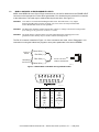
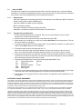
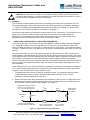
Instructions, Gaussmeter, Cable, and HALLCAL.EXE CAUTION: This Hall sensor is sensitive to electrostatic discharge (ESD). Use ESD precautionary procedures when handling, or making mechanical or electrical connections to this device in order to avoid performance degradation or loss of functionality. 1.0 GENERAL This document provides operation instructions for operating a Hall sensor with a Lake Shore 420, 421, 450, or 460 gaussmeter. Using a Hall sensor with a Lake Shore gaussmeter is described in Paragraph 1.1. MCBL-6 and MCBL-20 programmable cables details are provided in Paragraph 1.2. Finally, setup and operation of the Hallcal.exe software is described in Paragraph 1.3. Instructions in this chapter are intended for the low impedance “bulk” Hall sensors. The instructions do not apply to HGT-2100, HGT-2010, and HGA-2010 (which are intended for use with the Model 410 gaussmeter). The impedance and control current requirements of these three Hall sensors are not compatible with the Lake Shore gaussmeters that use the MCBL cables. 1.1 USING A HALL SENSOR WITH A LAKE SHORE GAUSSMETER To hook up a Hall sensor, you must use a Lake Shore MCBL-6 or MCBL-20 cable assembly (Paragraph 1.2). The MCBL-6 cable is 2 m (6.5 ft) long with a DA-15 connector on one end and four leads on the other. The MCBL-20 cable is 6 m (20 ft) long. The Hall sensor is a 4-lead device. The 4 leads are labeled +Ic (Red), –Ic (Black or Green), +VH (Blue), and –VH (Yellow), corresponding to the 4 leads on all the Hall sensors. The typical Lake Shore 421, 450, or 460 gaussmeter has an input impedance of 420 Ω. Therefore, the actual sensitivity at the gaussmeter input will be less than the value given with the Hall sensor due to drop in the leads and cable. This fact is important because a sensitivity value is supposed to be loaded into the cable PROM to set calibration. We recommend that the customer always check accuracy against a reference field rather than use the sensitivity value sent with the bare Hall generator. Because Lake Shore has no control of the conditions beyond the cable, the customer must accept responsibility for accuracy and compatibility. Finally, Manganin wire is not usually acceptable for gaussmeter connections. The resistance of Manganin wire is often too high. Hall generators are normally connected using twisted pairs of copper wire such as 34 gauge, Teflon insulated. There are two reasons for this: 1. The gaussmeter current source is limited in compliance voltage. The gaussmeter should not drive a load (Hall sensor, wires in cryostat, and probe cable) greater than 50 Ω. In fact, for best performance, the load should be less than 30 Ω. 2. Because the typical Lake Shore gaussmeter input impedance is 420 Ω, there is a voltage drop due to lead resistance in series with the gaussmeter input. The Lake Shore Hall sensor sensitivity given on the data sheet is basically with no lead resistance. See Figure 1-1. The gaussmeter needs input sensitivity between 0.5 to 1.5 mV/kG (HST) or 5.0 and 15 mV/kG (HSE) at its input Gaussmeter Input Rcable Rcust 420 VH Rcable Sensitivity at Gaussmeter input is reduced by the lead/input voltage divider Hall Generator Open Circuit Sensitivity Rcable = Lake Shore Model MCBL Cable Assembly Rcust Rcust = Customer Supplied Leads Impedance2.cvx Figure 1-1. Typical Hall Sensor Input Impedance Lake Shore Cryotronics, 575 McCorkle Blvd. Westerville, OH 43082 www.lakeshore.com Phone (614) 891-2243 – Fax (614) 891-1362 – [email protected] – [email protected] 1.2 MCBL-6 AND MCBL-20 ROGRAMMABLE CABLES MCBL-6 and MCBL-20 have 15-pin D-Style connectors on one end for attachment to the PROBE INPUT connector on the back panel of a Lake Shore gaussmeter. Four tinned wires are provided for connection to the Hall sensor. The leads may be soldered directly to these wires. See Figure 1-2. CAUTION: Care must be exercised when handling the Hall sensor. The Hall sensor is very fragile. Stressing the Hall sensor can alter its output. Any excess force can easily break the Hall sensor. Broken Hall sensors are not repairable. CAUTION: The Hall sensor should be isolated from all line voltages (or voltages referenced to earth ground). If not, damage to the gaussmeter is almost a certainty. CAUTION: The probe must be connected to the rear of the instrument before applying power to the gaussmeter. Probe memory may be erased if connected with power on. The DA-15 connector is detailed in Figure 1-3. Once connections are made, refer to Paragraph 1.3 for instructions on using the Hallcall.exe program to store probe parameters in the internal EPROM. Current to Sensor Hall Voltage from Sensor { { Green Wire (–) Red Wire (+) 6 Foot or 20 Foot Cable to Gaussmeter Blue Wire (+) Yellow Wire (–) MCBL6.eps Figure 1-2. Model MCBL-6 and MCBL-20 Programmable Cables Connector.eps Pin Description Pin Description 1 2 3 4 5 6 7 8 INPUT + NC NC ITEMP + ITEMP – NC NC Ic + 9 10 11 12 13 14 15 INPUT – NC GND 1 Vcc A/D CLK EE-DATA Ic – Figure 1-3. DA-15 Connector Details Form Number F048-00-00 Revision D — ©2014 Lake Shore Cryotronics, Inc. — 1 May 2014 1.3 HALLCAL.EXE The Hallcal.exe program was developed by Lake Shore to allow the interfacing of a customer attached Hall sensor to a Lake Shore gaussmeter. Because of the many intricacies involved with proper calibration, the Customer must accept responsibility for the measurement accuracy. 1.3.1 Requirements • • • • • 1.3.2 Lake Shore gaussmeter connected via RS-232 to the computer in the COM1 port. (NOTE: Computer interface cable must be a NULL MODEM type.) Lake Shore MCBL-6 or MCBL-20 cable assembly. IBM or compatible computer. Hall sensor meeting the sensitivity ranges given below. Calibration or sensitivity constant and serial number of the Hall sensor. Program Setup and Operation 1. Set the Lake Shore gaussmeter to 300 baud. Refer to your User’s Manual on how to set the gaussmeter to communicate at 300 baud. 2. Insert the disk into the computer and type in the default drive (A: or B:). 3. Either double click on Hallcal.exe or enter the command HALLCAL from the program line. This will execute the Hallcal.exe program. 4. The program will prompt for the Probe serial number. Any combination of 6 letters or number can be entered. Press Enter when this is accomplished. 5. The program will prompt for the probe type (0 or 1). Enter “0” for Hall sensors with sensitivities between 5.5 and 10.5 mV/kG (at 100 mA current). Enter “1” for Hall sensors with sensitivities between 0.55 and 1.05 mV/kG (at 100 mA current). 6. The program will prompt for the “Calibration Constant.” Enter the magnetic sensitivity in mV/kG at a control current of 100 mA. Remember to account for the 420 Ω input impedance of the gaussmeter when calculating the proper load resistor to install. 7. The program will display all the values entered along with designated F keys: F1 Probe Serial Number ABC123 F2 Probe Type 0 F3 Calibration Constant X.XXX F10 Program Probe Esc Exit Program 8. At this time, if any of the parameters need to be changed, just press the appropriate F key and type in the new value. When everything appears correct, press F10 to program the probe. 9. It takes about 20 s to program the probe. After the probe is programmed, press the Esc key to exit the program. SOFTWARE LICENSE AGREEMENT This software is protected by United States copyright law and international treaty provisions. Lake Shore provides this software package and grants you (the user of the software) a non-exclusive and non-transferable right to use this software. Unless as provided in this Agreement, any attempt to sublicense, lease, rent, assign, or transfer this license or this software is void. To maintain software warranty, the source code must not be modified. Any changes made to the HALLCAL.EXE source code are at the user's risk. Lake Shore will assume no responsibility for damage or errors incurred as result of any changes made to the source code. Under the terms of this agreement you may use the HALLCAL.EXE software on any one computer system. One archival disk is permitted. Any unauthorized duplication or use of the software in whole or in part, in print, or in any other storage and retrieval system is forbidden. Lake Shore has worked to ensure that the HALLCAL.EXE software is as free of errors as possible, and that the results you obtain from the system are accurate and reliable. However, understand that with any computer software the possibility of software exists. In any important research, as when using any laboratory equipment, results should be carefully examined and rechecked before final conclusions are drawn. Neither Lake Shore nor anyone else involved in the creation or production of this software can pay for loss of time, inconvenience, loss of use of the product, or property damage caused by this product or its failure to work, or any other incidental or consequential damages. Use of our product implies that you understand the Lake Shore license agreement and statement of limited warranty. Form Number F048-00-00 Revision D — ©2014 Lake Shore Cryotronics, Inc. — 1 May 2014