Download LED PAR 56 USER MANUAL - venue lighting effects
Transcript
LED PAR 56 USER MANUAL
www.venuelightingeffects.com
INTRODUCTION
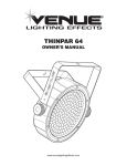
The LED PAR56 is a DMX intelligent LED Par Can. This Par Can is lightweight and compact which makes it a great piece
for mobile DJs, churches, and clubs. This unit can be used as a stand alone fixture in sound-activated mode, or controlled
via DMX controller.
WARNING
To prevent or reduce the risk of electrical shock or fire, do not expose this unit to moisture.
CAUTION
There are no user-serviceable parts inside this unit. Do not attempt any repairs yourself, doing so will void your
warranty.
PLEASE recycle the shipping carton whenever possible.
GENERAL INSTRUCTIONS
To optimize the performance of this product, please read these operating instructions carefully to familiarize yourself
with its basic operation. These instructions contain important safety information regarding the use and
maintenance of this unit. Please keep this manual for future reference.
FEATURES
• Multi-colors
• Color strobe
• Electronic dimming 0-100%
• Built in microphone
• DMX-512 protocol
• Uses six DMX channels
• Can be daisy chained via DMX Mode
Page 2
LED PAR 56 Instruction Manual
SAFETY PRECAUTIONS
• To reduce the risk of electrical shock or fire, do not expose this unit to moisture.
• Do not spill water or other liquids into or on your unit.
• Be sure that the local power outlet matches that of the required voltage for your unit.
• Do not attempt to operate this unit if the power cord has been frayed or broken. Do not attempt to remove or break
off the ground prong from the electrical cord. This prong reduces the risk of electrical shock and fire in case
of an internal short.
• Disconnect from main power before making any type of connection.
• Do not remove the cover under any conditions. There are no user-serviceable parts inside.
• Never operate this unit when its cover is removed.
• Never plug this unit into a dimmer pack.
• Always be sure to mount this unit in an area that will allow proper ventilation. Allow about 6” (15cm)
between this device and a wall.
• Do not attempt to operate this unit if it becomes damaged.
• This unit is intended for indoor use only. Use of this product outdoors voids all warranties.
• During long periods of non-use, disconnect the unit’s main power.
• Always mount this unit in a safe and stable manner.
• Power-supply cords should be routed so that they will not be walked on or pinched by items
placed upon or against them. Pay particular attention to the point where they exit the unit.
• The appliance should be situated away from heat sources such as radiators, heat registers, stoves, or other
appliances (including amplifiers) that produce heat.
• The fixture should be serviced by qualified service personnel when:
A. The power-supply cord or the plug has been damaged.
B. Objects have fallen, or liquid has been spilled into the appliance.
C. The appliance has been exposed to water.
D. The appliance does not appear to operate normally or exhibits a marked change in performance.
www.venuelightingeffects.com
Page 3
SET UP
Power Supply: Before plugging your unit in, be sure the source voltage in your area matches the required voltage for
your Venue LED PAR56. Because line voltage may vary from venue to venue, you should be sure your unit voltage
requirements match the wall outlet voltage before attempting to operate.
DMX-512: DMX is short for Digital Multiplex. This is a universal protocol used as a form of communication between
intelligent fixtures and controllers. A DMX controller sends DMX data instructions from the controller to the fixture. DMX
data is sent as serial data that travels from fixture to fixture via the DATA “IN” and DATA “OUT” XLR terminals located on
all DMX fixtures (most controllers only have a DATA “OUT” terminal).
DMX Linking: DMX is a language allowing all makes and models of different manufactures to be linked together and
operate from a single controller, as long as all fixtures and the controller are DMX compliant. To ensure proper DMX data
transmission, when using several DMX fixtures, try to use the shortest cable path possible. The order in which fixtures
are connected in a DMX line does not influence the DMX addressing. For example, a fixture assigned a DMX address
of 1 may be placed anywhere in a DMX line, at the beginning, at the end, or anywhere in the middle. When a fixture is
assigned a DMX address of 1, the DMX controller knows to send DATA assigned to address 1 to that unit, no matter
where it is located in the DMX chain.
Data Cable (DMX Cable) Requirements (For DMX Operation): The Venue LED PAR56 can be controlled via DMX-512
protocol. The Venue LED PAR56 is a six channel DMX unit. The DMX
address is set on the back panel of the Venue LED PAR56. Your unit and
your DMX controller require a standard 3-pin XLR connector for data input
and data output (Figure 1). If you are making your own cables, be sure to
use standard two conductor shielded cable (This cable may be purchased
at almost all pro sound and lighting stores). Your cables should be made
with a male and female XLR connector on either end of the cable. Also
remember that DMX cable must be daisy chained and cannot be split.
Notice: Be sure to follow Figures 2 and 3 when making your
own cables. Do not use the ground lug on the XLR connector. Do not
connect the cable’s shield conductor to the ground lug or allow the
shield conductor to come in contact with the XLR’s outer casing.
Grounding the shield could cause a short circuit and erratic behavior.
Special Note: Line Termination. When longer runs of cable are used, you
may need to use a terminator on the last unit to avoid erratic behavior. A
terminator is a 90-120 Ohm 1/4 watt resistor which is connected between
pins 2 and 3 of a male XLR connector (DATA + and DATA -). This unit is
inserted in the female XLR connector of the last unit in your daisy chain
to terminate the line. Using a cable terminator will decrease the possibilities of erratic behavior (Figure 4).
Figure 1
COMMON
DMX512 OUT
3-PIN XLR
DMX +
1
3
1
3
DMX -
2
2
DMX512 IN
3-PIN XLR
XLR Pin Configuration
Pin 1 = Ground
Pin 2 = Data Compliment (negative)
Pin 3 = Data True (positive)
Figure 2
XLR Female Socket
XLR Male Socket
1 Ground
2 Cold
2 Cold
1 Ground
3 Hot
3 Hot
Figure 3
1
3
2
Termination reduces signal errors and
avoids signal transmission problems
and interference. It is always advisable
to connect a DMX terminal, (Resistance
120 Ohm 1/4 W) between PIN 2 (DMX-)
and PIN 3 (DMX +) of the last fixture.
Figure 4
Page 4
LED PAR 56 Instruction Manual
OPERATING INSTRUCTIONS
Operating Modes:
You can use the LED PAR56 in four ways:
• Sound-Active mode - Reacts to sound, chasing through the built-in programs.
• Auto Mode - Automatically chases through the different colors.
• RGB Mode - Projects a single static color.
• DMX control mode - This function will allow you to control each individual fixture with a standard
DMX 512 controller.
Sound Active Mode:
In this mode the LED PAR56 will react to sound and chase through the different colors.
1. Plug the fixture in and put DIP switch #10 in the “ON” position.
2. The fixture will now be controlled by sound.
Auto Mode:
1. Plug the fixture in and put DIP switches #9 and #10 in the “ON” position.
2. Adjust the speed by adjusting DIP switches #1 through #7.
RGB Mode:
1. Plug the fixture in and put DIP switches #8, #9, and #10 in the “ON” position.
2. D
IP switch #1 alone will project Red at 25% intensity, DIP switch #2 alone will project Red at 50% intensity. Combine
DIP switches #1 & #2 and Red will be projected at 100% intensity.
DIP switch #3 alone will project Green at 25% intensity, DIP switch #4 alone will project Green at
50% intensity. Combine DIP switches #3 & #4 and Green will be projected at 100% intensity.
DIP switch #5 alone will project Blue at 25% intensity, DIP switch #6 alone will project Blue at 50% intensity. Combine
DIP switches #5 & #6 and Blue will be projected at 100% intensity.
DMX Mode:
Operating through a DMX controller gives the user the freedom to create their own programs tailored to their
individual needs. This function also allows you to use your fixtures as spotlights.
1. The LED64 PAR uses six DMX channels to operate.
2. To run your fixture in DMX mode, plug in the fixture via XLR connections to any standard DMX controller.
3. Set your desired DMX address following the set-up specifications that came with your DMX controller.
www.venuelightingeffects.com
Page 5
DMX VALUES AND FUNCTIONS
Channel
1
Value
Function
0 - 255
0%
2
0 - 255
3
0 - 255
RED
100%
GREEN
0%
100%
0%
BLUE
100%
4
8 - 255
COLOR MACRO
5
0 - 15
16 - 255
NOTHING
STROBING
6
0 - 31
NOTHING
DIMMING CONTROL
DIM
BRIGHT
BRIGHT
DIM
DIM
BRIGHT
DIM
COLOR MIXING
3 COLOR CHANGE
7 COLOR CHANGE
SOUND ACTIVE
32 - 63
64 - 95
96 - 127
128 - 159
160 - 191
192 - 223
224 - 255
Channel 1, 2, and 3 will not work when Channel 4 is being used. When units are daisy chained together
in DMX Mode, Channels 1, 2, and 3 must be “OFF” for units to sync together when using Channel 4.
When the value of Channel 6 is between 32 and 127, you must be using Channels 1, 2, or 3, or all
three combined.
When using Channel 6, Channel 5 will control the speed of the color changes.
CLEANING
Due to fog residue, smoke, and dust, clean the internal and external optical lenses
periodically to optimize light output.
1. Use normal glass cleaner and a soft cloth to wipe down the outside case.
2. Clean the external optics with glass cleaner and a soft cloth every 20 days.
3. A
lways dry all parts completely before plugging the unit back in. Cleaning frequency depends on
the environment in which the fixture operates (i.e. smoke, fog residue, dust, dew).
Page 6
LED PAR 56 Instruction Manual
TROUBLE SHOOTING
Unit not responding to DMX:
1. Check that the DMX cables are connected and wired correctly (pin 3 is ‘hot’; on some other DMX devices pin 2 may be
‘hot’). Also, check that all cables are connected to the right connectors; it does matter which way the inputs and outputs
are connected.
Unit does not respond to sound:
1. Quiet or high pitched sounds will not activate the unit.
SPECIFICATIONS
Please Note: Specifications and
improvements in the design of this
unit and this manual are subject
to change without any prior
written notice.
WARRANTY
Model: LED PAR56
SPECIFICATIONS:
Working Position: Voltage: Power Draw:
Weight: Dimensions: Colors:
Any safe working position
120V AC
0.2 Amps
4 lbs./1.8 kg.
(L) 9” x (W) 9” x (H) 12”
RGB Color Mixing
One (1) Year Limited Warranty
Subject to the limitations set forth below, Venue™ hereby represents and warrants that the components of this product
shall be free from defects in workmanship and materials, including implied warranties of merchantability or fitness for a
particular purpose, subject to normal use and service, for one (1) year (ninety (90) days on lamps) to the original owner
from the date of purchase.
Retailer and manufacturer shall not be liable for damages based upon inconvenience, loss of use of product, loss of
time, interrupted operation or commercial loss or any other incidental or consequential damages including but not limited
to lost profits, downtime, goodwill, damage to or replacement of equipment and property, and any costs of recovering,
reprogramming, or reproducing any program or data stored in equipment that is used with Venue™ products. This
guarantee gives you specific legal rights. You may have other legal rights which vary from state to state. Some states
do not allow limitations on how long an implied warranty lasts, so the above limitation may not apply to you.
Venue Lighting Effects
P.O. Box 5111
Thousand Oaks, CA 91359-5111
www.venuelightingeffects.com
All trademarks and registered trademarks mentioned herein are recognized as the property of their
respective holders. Made in China
0804-8099A
www.venuelightingeffects.com
Page 7
Important safety instructions
This symbol is intended to alert the user to the
presence of non-insulated “dangerous voltage”
within the products enclosure.
This symbol is intended to alert the user to the
presence of important operating and maintenance
(servicing) instructions in the literature accompanying
the unit.
Apparatus shall not be exposed to dripping or splashing.
Objects filled with liquids, such as vases, shall not be
placed on the apparatus.
1. Read all safety and operating instructions before using this product.
2. All safety and operating instructions should be kept for future reference.
3. Read and understand all warnings listed on the operating instructions.
4. Follow all operating instructions to operate this product.
5. This product should not be used near water, i.e., bathtub, sink, swimming pool, wet basement, etc.
6. Only use dry cloth to clean this product.
7. Do not block any ventilation openings, it should not be placed flat against a wall or placed in a built-in enclosure
that will impede the flow of cooling air.
8. Do not install this product near any heat sources such as radiators, heat registers, stoves or other apparatus
(including amplifiers) that produce heat.
9. Do not defeat the safety purpose of the polarized or grounding-type plug. A polarized plug has two blades with
one wider than the other. A grounding-type plug has two blades and a third grounding prong. The wide blade or
the third prong are provided for your safety. If the provided plug does not fit into your outlet, consult an electrician
for replacement of the obsolete outlet.
10. Protect the power cord from being walked on or pinched, particularly at plugs, convenience receptacles, and the
point where they exit from the apparatus. Do not break the ground pin of the power supply cord.
11. Only use attachments specified by the manufacturer.
12. Use only with the cart, stand, tripod, bracket, or table specified by the manufacturer
or sold with the apparatus. When a cart is used, exercise caution when moving.
13. Unplug this apparatus during lightning storms or when unused for a long period of time.
14. Care should be taken so that objects do not fall and liquids are not spilled into the unit through
the ventilation ports or any other openings.
15. Refer all servicing to qualified service personnel. Servicing is required when the apparatus has been
damaged in any way.
16. WARNING: To reduce the risk of fire or electric shock, do not expose this apparatus to rain or moisture.
17. When a mains plug or an appliance coupler is used as the disconnect device, the disconnect device shall
remain readily operable.


