1
L8-Family AT Commands
User Manual
Version:V1.1.3
Date:2015.09.28
Copyright
Copyright ©2015 Fibocom Wireless Inc . All rights reserved.
Without the prior written permission of the copyright holder, any company or individual is prohibited to
excerpt, copy any part of or the entire document, or transmit the document in any form.
Attention
The document is subject to update from time to time owing to the product version upgrade or other
reasons. Unless otherwise specified, the document only serves as the user guide. All the statements,
information and suggestions contained in the document do not constitute any explicit or implicit
guarantee.
Trademark
The trademark is registered and owned by Fibocom Wireless Inc.
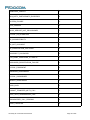
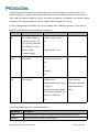
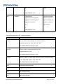
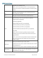
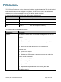
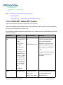
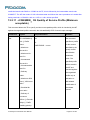
Versions
Version
Date
Remarks
V1.0.0
2014-07-11
Initial Version Based on H350
V1.0.1
2014-09-01
Add GTRAT
V1.0.2
2014-08-30
Update CSMP CPBR
V1.0.3
2014-09-10
V1.0.4
2014-11-07
Update XCESQ
V1.0.5
2014-11-26
Update CPBS
Update CPBW
Add CLK32K
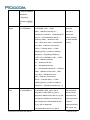
Change file name from FIBOCOM_L8-Family AT
V1.0.6
2014-12-17
Commands User Manual_V1.0.5 to L810-GL AT
Commands User Manual_V1.0.6
Update CEREG, IPR
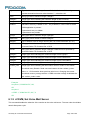
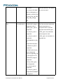
V1.0.7
2015-01-04
V1.0.8
2015-01-26
L8-Family AT Commands User Manual
The company name is changed.
Update GTUMODE
Update CGSMS
Page 2 of 284
Update CPMS
Add CBAUD
Add L830-GL
Update GTUMODE CGDCONT
V1.0.9
2015-03-18
Change the name to FIBOCOM _L8-Family AT
Commands User Manual_V1.0.9
Updated several AT commands for IA (CREG, CGREG,
CEREG, XREG)
Update CIMI, CGSN, CRSM, GTSET, GTRAT,
V1.1.0
2015-04-23
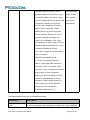
V1.1.1
2015-04-26
Update the description of copyright and attention.
V1.1.2
2015-08-25
Update the logo.
V1.1.3
2015-09-28
Add the TCP/IP.
GTWAKE,CREG,CGREG,CEREG
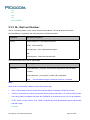
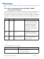
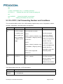
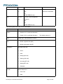
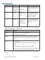
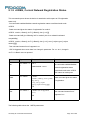
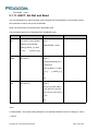
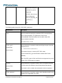
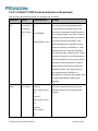
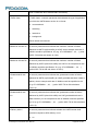
Applicability Type
No.
Type
1
L810-GL
2
L830-GL
Note
L8-Family AT Commands User Manual
Page 3 of 284
Contents
1 Preface................................................................................................................................................................... 10
1.1 Manual Scope............................................................................................................................................10
1.2 Target Audience........................................................................................................................................ 10
2 Introduction to AT Commands........................................................................................................................... 11
2.1 AT Commands Overview.........................................................................................................................11
2.2 General System Abbreviations............................................................................................................... 11
2.3 AT Commands Protocol...........................................................................................................................11
2.4 AT Commands Structure......................................................................................................................... 12
2.4.1 General Symbols Used in AT Commands Description........................................................... 12
2.4.2 Command Structure...................................................................................................................... 13
2.4.3 Results Code Structure................................................................................................................ 13
2.5 Command Syntax..................................................................................................................................... 14
3 Modem ID.............................................................................................................................................................. 15
3.1 +CGMI, +GMI, Request Manufacturer ID............................................................................................. 15
3.2 +CGMM, +GMM, +FMM, Request Model ID........................................................................................15
3.3 +CGMR, +GMR, +FMR, Request Revision..........................................................................................16
3.4 +CGSN, +GSN, Request Product Serial Number Identification....................................................... 16
3.5 +CSCS, Select Terminal Character Set................................................................................................17
3.6 +CIMI, Request IMSI................................................................................................................................ 18
3.7 +CFSN, Read Factory Serial Number...................................................................................................19
3.8 I, Request Identification Information...................................................................................................... 19
3.9 +CNUM, Request MSISDN(s)................................................................................................................ 20
3.10 +CLAC, List of All Available AT Commands...................................................................................... 21
4 Modem Control and Status................................................................................................................................. 23
4.1 Modem Register Commands.................................................................................................................. 23
4.1.1 V, Modem Response Format.......................................................................................................23
4.1.2 Q, Result Code Suppression....................................................................................................... 24
4.1.3 E, Command Echo........................................................................................................................ 25
4.1.4 X, Result Code Selection and Call Progress Monitoring Control..........................................25
4.1.5 S, Bit Map Registers..................................................................................................................... 27
4.1.6 S2..................................................................................................................................................... 28
4.1.7 S12................................................................................................................................................... 29
4.1.8 &F, Set to Factory Defined Configuration................................................................................. 29
L8-Family AT Commands User Manual
Page 4 of 284
4.1.9 Z, Reset to Default Configuration............................................................................................... 30
4.1.10 +CRSM, Restricted SIM Access...............................................................................................31
4.1.11 +CCID............................................................................................................................................37
4.2 Port Change Commands......................................................................................................................... 38
4.2.1 GTUSBMODE, Set USB Mode................................................................................................... 38
4.3 GTSET Command.................................................................................................................................... 39
4.3.1 GTSET, Set the proprietary parameters of Fibocom...............................................................39
4.4 Error Handling Commands......................................................................................................................40
4.4.1 +CMEE, Report Mobile Equipment Error.................................................................................. 40
4.4.2 +CEER, Extended Error Report..................................................................................................42
5 Call Control............................................................................................................................................................ 43
5.1 Managing a CSD (Data) Call.................................................................................................................. 43
5.1.1 Simple Dialing................................................................................................................................ 43
5.1.2 Switching From Data Mode to Command Mode...................................................................... 44
5.1.3 Hanging Up.....................................................................................................................................44
5.2 Receiving a Data Call...............................................................................................................................44
5.3 Call Control AT Commands.................................................................................................................... 45
5.3.1 D, Dial Command.......................................................................................................................... 45
5.3.2 D>, Direct Dialing from Phone Books........................................................................................ 46
5.3.3 DL, Dial Last Number....................................................................................................................48
5.3.4 H, Hang-up Call............................................................................................................................. 49
5.3.5 A, Answer Incoming Call.............................................................................................................. 51
5.3.6 +CRC, Cellular Result Codes and RING, +CRING - Incoming Call Indication...................52
5.3.7 +CLIP, Calling Line Identification................................................................................................55
5.3.8 +CLIP Indication............................................................................................................................ 56
5.3.9 +CCWA, Call Waiting Command................................................................................................57
5.3.10 +CCWA Indication.......................................................................................................................59
5.3.11 +CHLD, Call Related Supplementary Services Command.................................................. 61
5.3.12 +CCFC, Call Forwarding Number and Conditions................................................................ 64
5.3.13 +CLIR, Calling Line Identification Restriction......................................................................... 66
5.3.14 +CBST, Select Bearer Service Type....................................................................................... 69
5.3.15 O, Return to Online Data State.................................................................................................72
5.3.16 +CHUP, Hang Up Call................................................................................................................72
5.4 Call Status Messages...............................................................................................................................73
5.4.1 +CPAS, Phone Activity Status.................................................................................................... 73
L8-Family AT Commands User Manual
Page 5 of 284
5.4.2 +CLCC, List Current Calls............................................................................................................74
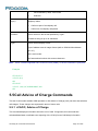
5.5 Call Advice of Charge Commands.........................................................................................................76
5.5.1 +CAOC, Advice of Charge...........................................................................................................76
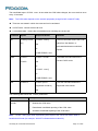
5.5.2 +CACM, Accumulated Call Meter...............................................................................................79
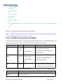
5.5.3 +CAMM, Accumulated Call Meter Maximum............................................................................80
5.5.4 +CPUC, Price per Unit and Currency Table............................................................................. 82
5.5.5 +CR, Service Reporting Control................................................................................................. 83
5.6 Supplementary Services..........................................................................................................................84
5.6.1 +CSSN, Supplementary Service Notifications......................................................................... 84
5.6.2 +CUSD, Unstructured Supplementary Service Data.............................................................. 88
5.6.3 +COLP, Connected Line Identification Presentation...............................................................93
6 Phone Book and Clock........................................................................................................................................ 96
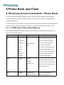
6.1 Directory Access Commands - Phone Book........................................................................................96
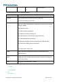
6.1.1 +CPBS, Select Phone Book Memory........................................................................................ 96
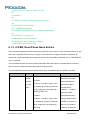
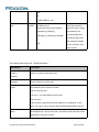
6.1.2 +CPBR, Read Phone Book Entries............................................................................................98
6.1.3 +CPBF, Find Phone Book Entries............................................................................................101
6.1.4 +CPBW, Write Phone Book Entry............................................................................................ 103
6.1.5 +CSVM, Set Voice Mail Server.................................................................................................105
6.2 System Date and Time Access Commands...................................................................................... 107
6.2.1 +CCLK, Read/Set System Date and Time............................................................................. 107
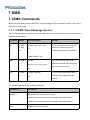
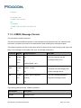
7 SMS...................................................................................................................................................................... 110
7.1 SMS Commands.....................................................................................................................................110
7.1.1 +CSMS, Select Message Service............................................................................................ 110
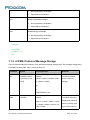
7.1.2 +CPMS, Preferred Message Storage...................................................................................... 111
7.1.3 +CMGF, Message Format......................................................................................................... 113
7.1.4 +CSCA, Service Center Address............................................................................................. 114
7.1.5 +CSMP, Set Text Mode Parameters....................................................................................... 118
7.1.6 +CSDH, Show Text Mode Parameters....................................................................................120
7.1.7 +CNMI, New Message Indications to Terminal......................................................................122
7.1.8 +CNMA, New Message Acknowledgment.............................................................................. 125
7.1.9 +CMTI, Unsolicited Response (New SMS-DELIVER Receipt Indication).........................127
7.1.10 +CMT, Unsolicited Response (New SMS-DELIVER Receipt).......................................... 128
7.1.11 +CBM, Unsolicited Response (New CB Message Receipt).............................................. 130
7.1.12 +CDSI, Unsolicited Response (New SMS-STATUS-REPORT Indication).....................131
7.1.13 +CDS, Unsolicited Response (New SMS-STATUS-REPORT Receipt)......................... 132
L8-Family AT Commands User Manual
Page 6 of 284
7.1.14 +CMGL, List Messages............................................................................................................133
7.1.15 +CMGR, Read Message..........................................................................................................137
7.1.16 +CMSS, Send Message from Storage.................................................................................. 141
7.1.17 +CMGW, Write Message to Memory.....................................................................................142
7.1.18 +CMGD, Delete Message........................................................................................................145
7.1.19 +CGSMS, Select Service for MO SMS Messages..............................................................146
7.1.20 +CMGS, Send SMS to Network............................................................................................. 147
7.1.21 +CSCB, Cell Broadcast Messages........................................................................................ 149
8 Access and security...........................................................................................................................................152
8.1 A/, Repeat Last Command....................................................................................................................152
8.2 AT, Check AT Communication............................................................................................................. 152
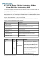
8.3 +CPIN, Enter PIN for Unlocking SIM or Enter PUK for Unblocking SIM...................................... 153
8.4 +CPWD, Change Password................................................................................................................. 157
8.5 +CLCK, Facility Lock..............................................................................................................................160
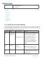
9 Network................................................................................................................................................................ 164
9.1 Network Commands...............................................................................................................................164
9.1.1 +CSQ, Signal Strength...............................................................................................................164
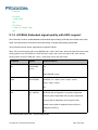
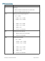
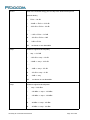
9.1.2 +XCESQ, Extended signal quality with URC support...........................................................165
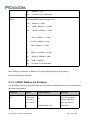
9.1.3 +CRLP, Radio Link Protocol..................................................................................................... 168
9.1.4 +CREG, Network Registration Status......................................................................................170
9.1.5 +CGREG, GPRS Network Registration.................................................................................. 173
9.1.6 +CEREG, EPS Network Registration status.......................................................................... 176
9.1.7 +COPS, Operator Selection...................................................................................................... 179
9.1.8 +CPOL, Preferred Operators.................................................................................................... 183
9.1.9 +XREG, Current Network Registration Status....................................................................... 187
9.1.10 +GTUMODE, URAT mode switch..........................................................................................193
9.1.11 +XACT, Set Rat and Band.......................................................................................................194
9.1.12 +GTRAT, Selection of Radio Access Technology.............................................................. 199
9.2 Other Parameter Commands............................................................................................................... 202
9.2.1 +CBC, Battery Charger Connection.........................................................................................202
9.2.2 +CFUN, Shut Down Phone Functionality................................................................................202
9.2.3 +CPWROFF Switch off MS....................................................................................................... 205
9.2.4 +MMAD, Query and Monitor ADC Value................................................................................ 205
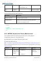
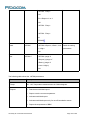
9.2.5 +MTSM, Temperature Sensor Measurement.........................................................................206
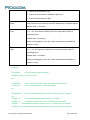
9.2.6 +MSMPD, Enable/Disable SIM card hot plug........................................................................ 209
L8-Family AT Commands User Manual
Page 7 of 284
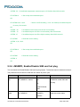
9.2.7 +GPIO, Set and Read GPIO..................................................................................................... 210
9.2.8 +GTWAKE,Open or close wake host...................................................................................... 211
9.3 Multiplexer Feature.................................................................................................................................213
9.3.1 +CMUX, MUX Start up Command........................................................................................... 213
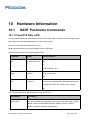
10 Hardware Information......................................................................................................................................216
10.1 UART Parameter Commands............................................................................................................ 216
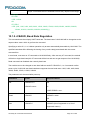
10.1.1 Fixed DTE Rate +IPR...............................................................................................................216
10.1.2 +CBAUD, Baud Rate Regulation........................................................................................... 217
10.1.3 &D, Circuit 108 Behavior......................................................................................................... 218
11 Audio.................................................................................................................................................................. 220
11.1 Scope......................................................................................................................................................220
11.2 General Audio Commands................................................................................................................. 220
11.2.1 +CMUT, Mute/Unmute Microphone and Speaker Path..................................................... 220
11.2.2 +VTD, Tone Duration............................................................................................................... 221
11.2.3 +VTS, Command-Specific Tone Duration............................................................................ 222
11.3 Clock Configuration..............................................................................................................................223
11.3.1 +CLK32k, 32KHz Clock Output From CLK32K................................................................... 223
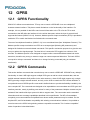
12 GPRS................................................................................................................................................................. 225
12.1 GPRS Functionality..............................................................................................................................225
12.2 GPRS Commands................................................................................................................................225
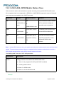
12.2.1 +CGCLASS, GPRS Mobile Station Class............................................................................ 226
12.2.2 +CGDCONT, Define PDP Context........................................................................................ 227
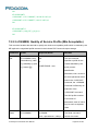
12.2.3 +CGQMIN, Quality of Service Profile (Min Acceptable).....................................................232
12.2.4 +CGQREQ, Quality of Service Profile (Requested)............................................................234
12.2.5 +CGATT, GPRS Attach or Detach.........................................................................................236
12.2.6 D*99, Request GPRS Service "D"......................................................................................... 237
12.2.7 +CGACT, PDP Context Activate or Deactivate................................................................... 240
12.2.8 +CGPADDR, GPRS Addresses............................................................................................. 241
12.2.9 +CGANS, Manual response to a network request for PDP context activation.............. 243
12.2.10 +CGAUTO, Automatic Response to a Network Request for PDP Context Activation245
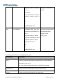
12.2.11 +CGEQMIN,3G Quality of Service Profile (Minimum acceptable).............................. 247
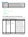
12.2.12 +CGEQREQ,3G Quality of Service Profile (Requested).............................................. 253
12.2.13 +CGEQNEG,G Quality of Service Profile (Negotiated).................................................259
12.2.14 +CGCMOD,PDP Context Modify...................................................................................... 262
12.2.15 +CGDATA ,Enter Data State............................................................................................ 264
L8-Family AT Commands User Manual
Page 8 of 284
12.2.16 +CGDSCONT,Define Secondary PDP Context............................................................. 265
12.2.17 +CGEREP,Packet Domain Event Reporting.................................................................. 267
12.2.18 +CGTFT Traffic Flow Template............................................................................................269
12.2.19 +CGEV, Unsolicited Packet Domain Event Reporting..................................................... 272
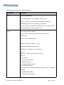
13
TCP/IP.............................................................................................................................................................274
13.1 Basic Mode............................................................................................................................................ 274
13.1.1 +MSDNS, Set DNS IP Address..............................................................................................274
14 Error Code.........................................................................................................................................................277
14.1 CME Error.............................................................................................................................................. 277
14.2 CMS Error.............................................................................................................................................. 280
14.3 TCP/IP Error.......................................................................................................................................... 283
L8-Family AT Commands User Manual
Page 9 of 284
1 Preface
1.1Manual Scope
This manual introduces the L8 family AT command set, and describes how software developers can use
these commands to communicate with the device, and to create software applications that communicate
with the device using these commands.
Note:
The integrator should read the corresponding SW release notes corresponding to the product
version in using to get information about differences from this manual.
1.2Target Audience
This manual is intended for software developers who communicate with the L8 family device using the
AT commands, and create applications to communicate with the device using the AT commands.
L8-Family AT Commands User Manual
Page 10 of 284
2 Introduction to AT Commands
2.1AT Commands Overview
AT commands are sets of commands used for communication with the cellular modem. AT commands
are comprised of assemblies of ASCII characters which start with the "AT" prefix (except the commands
A/ and +++). The AT prefix is derived from the word Attention, which asks The modem to pay attention to
the current request (command).
AT commands are used to request services from the cellular modem, such as:
Call services: dial, answer and hang up
Cellular utilities: send/receive SMS
Modem profiles: Auto Answer
Cellular Network queries: GSM signal quality
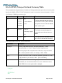
2.2General System Abbreviations
The basic system configuration contains a modem and a terminal.
The L8 family is The modem unit and may be referred to as the DCE or TA, such as the phone, the
mobile or the radio.
The terminal (PC or MCU) may be referred to as the DTE or the TE.
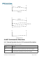
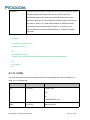
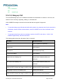
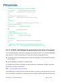
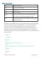
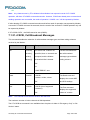
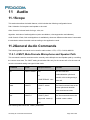
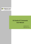
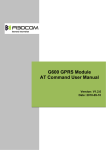
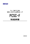
2.3AT Commands Protocol
The AT commands interface is basically a Modem Services upon Request.
Communication (almost) always begins from the TE side. This means that any service should be
requested from the TE. Thus a request is called a "Command".
Each command must be answered by a "Results code" from the TA. The results code reports the
command status to the TE. Some commands may include several "Results code" to send data back to
the TE. Some commands may initiate a mode in which, when specified events are generated in the
modem, "Indicator" messages are sent data asynchronously. The “indicators” can be called “Unsolicited
results code”.
The Modem can echo characters received from the TE (commands) back to the TE.
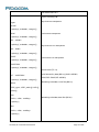
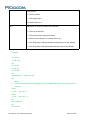
TE
TA
Command
Results code
TE
TA
Command
Results code
TA
TE
Unsolicited results code
2.4AT Commands Structure
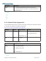
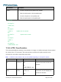
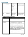
2.4.1 General Symbols Used in AT Commands Description
The following syntax definitions apply in this chapter :
Syntax
Definition
<CR>
Carriage returns character, specified by the value of the S3-register.
<LF>
Line-feed character, specified by the value of the S4-register.
L8-Family AT Commands User Manual
Page 12 of 284
<…>
Name enclosed in angle brackets is a syntax element. The brackets
themselves do not appear in the command line.
[...]
Optional sub-parameter of a command or an optional part of terminal
information response, enclosed in square brackets. The brackets themselves
do not appear in the command line. When the sub-parameter is not provided
in the parameter type commands, the new value equals its previous value. In
action type commands, the action should be performed on the basis of the
recommended default setting of the sub-parameter.
//
Denotes a comment, and should not be included in the command.
2.4.2 Command Structure
Each AT command has the "AT" or “at” prefix string (except the commands A/ and +++).
Each AT command has the suffix <CR> (except the commands A/ and +++).
Example:
AT+CSQ<CR>
ATS24?<CR>
An AT command line may contain one or more commands. Delimiters are used to separate the
commands from each other. The delimiter is either a semicolon ";" or none, meaning space (basic
commands).
Example:
ATS0=1V1Q0E0<CR>
AT+IFC=0,0;+ICF=3,4;+CNMI=2,1,0,0,0<CR>
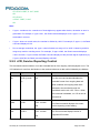
2.4.3 Results Code Structure
By default, the Modem responds with verbose response codes. The results code prefix is <CR><LF>.
The results code suffix is <CR><LF>.
Example:
<CR><LF>+CSQ: 99,99<CR><LF>
<CR><LF>OK<CR><LF>
The unsolicited results code is same as the Results code.
L8-Family AT Commands User Manual
Page 13 of 284
2.5Command Syntax
Execute command syntax
AT+xxx
ATxxx
ATxxx;
Parameter set command syntax
AT+xxx=<Value>
ATxxx=<Value>
Parameter read Command syntax
AT+xxx?
ATxxx?
Parameter test Command syntax
AT+xxx=?
ATxxx=?
<Value> consists of either a numeric constant or a string constant. <compound_value> consist of several
<value> parameters separated by commas.
Example of compound_value: <value1>, <value2>,…,<valueN>
Numeric Constants
Numeric constants are expressed in decimal, hexadecimal, or binary form. In the Modem, the
definition of each command specifies which form is used for values associated with that command.
String Constants
String constants consist of a sequence of characters, bounded at the beginning and end by the
double-quote character (").
L8-Family AT Commands User Manual
Page 14 of 284
3 Modem ID
These commands allow the user to query the type of device that is attached, the technology used in the
device, as well as basic operating information about the modem unit.
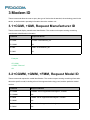
3.1+CGMI, +GMI, Request Manufacturer ID
These commands display manufacturer identification. The modem unit outputs a string containing
manufacturer identification information.
Command
Response/Action
AT+CGMI
+CGMI: <manufacturer_ID>
AT+CGMI?
OK
AT+GMI
+GMI: <manufacturer_ID>
AT+GMI?
OK
Example:
AT+CGMI
+CGMI: "Fibocom"
OK
3.2+CGMM, +GMM, +FMM, Request Model ID
These commands request the model identification. The modem outputs a string containing information
about the specific model, including a list of the supported technology used, and the particular model
number.
Command
Response/Action
AT+CGMM
+CGMM: <list of supported technologies>,<model>
AT+CGMM?
OK
AT+GMM
+GMM: <list of supported technologies>,<model>
AT+GMM?
OK
AT+FMM
+FMM: <list of supported technologies>,<model>
AT+FMM?
OK
Example:
AT+CGMM?
+CGMM: "L810 LTE Module","L810"
OK
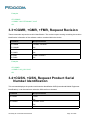
3.3+CGMR, +GMR, +FMR, Request Revision
These commands request the revision identification. The modem outputs a string containing the revision
identification information of the software version contained within the device.
Command
Response/Action
AT+CGMR
+CGMR: <revision>
AT+CGMR?
OK
AT+GMR
+GMR: <revision>
AT+GMR?
OK
AT+FMR
+FMR: <revision>
AT+FMR?
OK
Example:
AT+CGMR
+CGMR: "L810_V0L.00.01"
OK
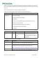
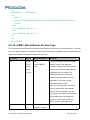
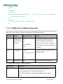
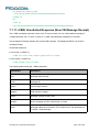
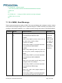
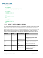
3.4+CGSN, +GSN, Request Product Serial
Number Identification
This command displays the product serial number identification IMEI (International Mobile Equipment
Identification). It can be used even when the SIM card is not inserted.
Command
Response/Action
AT+CGSN
<imei>
OK
AT+CGSN?
+CGSN: <imei>
OK
AT+GSN
L8-Family AT Commands User Manual
+GSN: <imei>
Page 16 of 284
AT+GSN?
OK
The following table shows the +CGSN, +GSN parameters.
<Parameter>
Description
<imei>
The IMEI (International Mobile Station Equipment Identity) number is
composed of 15 digits, as specified by 3GPP TS 23.003. IMEI numbers
are composed of the following elements, all in decimal digits:
Type Approval Code (TAC) - 8 digits
Serial Number (SNR) - 6 digits
Spare digit - 1 digit
The TAC and SNR are protected against unauthorized changes.
Example:
AT+CGSN
865204020007540
OK
AT+CGSN?
+CGSN: "865204020007540"
OK
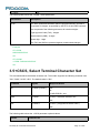
3.5+CSCS, Select Terminal Character Set
This command selects the Modem character set. The modem supports the following character sets:
"IRA","GSM","UCS2","HEX". The default value is “IRA”.
Command
Syntax
Response/Action
Set
+CSCS=[<chset>]
OK
or:
+CMS ERROR: <err>
Read
+CSCS?
+CSCS: <selected character set>
OK
Test
+CSCS=?
+CSCS: (<supported character sets>)
OK
The following table shows the +CSCS parameter optional values.
<chset>
Character Set
L8-Family AT Commands User Manual
Page 17 of 284
“IRA”
International Reference Alphabet (ITU-T T.50)
“GSM”
GSM default alphabet (GSM 03.38 subclause 6.2.1)
"UCS2"
2-byte Universal Character Set, Unicode (ISO/IEC 10646 [32])
“HEX”
Character strings consist only of hexadecimal numbers from 00 to FF
Example:
AT+CSCS=?
+CSCS: ("UCS2", "IRA", "HEX", "GSM")
OK
AT+CSCS?
+CSCS: "IRA"
OK
AT+CPBS="SM"
OK
AT+CPBW=1,"8475763000",129,"Lin Zhao"
OK
AT+CSCS="UCS2"
OK
AT+CPBR=1
+CPBR: 1,"8475763000",129,”004C0069006E0020005A00680061006F”
OK
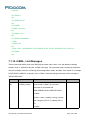
3.6+CIMI, Request IMSI
This command displays the International Mobile Subscriber Identity number.
Command
Response/Action
AT+CIMI
<imsi>
OK
or:
+CME ERROR: <err>
AT+CIMI?
+CIMI: <imsi>
OK
or:
L8-Family AT Commands User Manual
Page 18 of 284
+CME ERROR: <err>
Example:
AT+CIMI
314566320021400
OK
AT+CIMI?
+CIMI: 314566320021400
OK
3.7+CFSN, Read Factory Serial Number
This command is used to query the factory serial number.
Command
Response/Action
AT+CFSN
+CFSN: <fsn>
AT+CFSN?
OK
Example:
AT+CFSN
+CFSN: “1234567890”
OK
3.8I, Request Identification Information
This command displays various modem information items.
Command
Response/Action
ATIn
<information item n>
or:
+CME ERROR: <err>
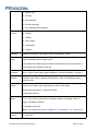
The following table shows the information items that are supported by the Modem.
L8-Family AT Commands User Manual
Page 19 of 284
ATIn
Description
Output (Just Demo)
ATI
Same as ATI0
ATI0
Build time
ATI1
Reserve
"Reserve"
ATI2
Reserve
"Reserve"
ATI3
Product description
"Fibocom LTE Module"
ATI4
Reserve
"Reserve"
ATI5
Platform
"XMM7262"
ATI6
Reserve
"Reserve"
ATI7
Product description
"L810 LTE Module"
ATI8
Software version
"L810_V0L.00.01"
ATI9
Reserve
"L810-GL-00 V1.0.0"
Remark
".Built@Jul 24
2014:10:15:45"
".Built@Jul 24
2014:10:15:45"
Note: For L810, L830 are
not supported now.
3.9+CNUM, Request MSISDN(s)
This command displays up to 2 strings of text information that identify the modem. The output string
contains double quotes.
On SIM cards that have EFmsisdn file, the string(s) returned are the MSISDN numbers and their
associated data.
On SIM cards that don't have EFmsisdn file, the strings returned are the MSISDN numbers and their
associated data stored in Modem NVM.
Note: For L810-GL, L830-GL,+CNUM? are not supported.
Command
L8-Family AT Commands User Manual
Response/Action
Page 20 of 284
+CNUM
+CNUM:
[<MSISDN1_string>],<MSISDN1>,<MSISDN1_type><CR><LF>
+CNUM?
[+CNUM:
(MSISDN supported)
[<MSISDN2_string>],<MSISDN2>,<MSISDN2_type>]<CR><LF
>
[...]
OK
+CNUM
+CNUM: <phone_number>
+CNUM?
OK
(MSISDN not supported)
The following table shows the +CNUM parameters.
<Parameter>
Description
<MSISDN type>
Phone number type
129 Use for local call
145 Use “+” for international access code
128 Unknown
Example:
AT+CNUM
+CNUM: "VoiceMail","13812345678",129
OK
3.10 +CLAC, List of All Available AT
Commands
This command prints out all AT Commands supported by the Modem.
Command
Syntax
L8-Family AT Commands User Manual
Response/Action
Remarks
Page 21 of 284
Execute
+CLAC
List of available AT
The Execute command displays a list of
commands
all the AT commands supported by the
Modem.
L8-Family AT Commands User Manual
Page 22 of 284
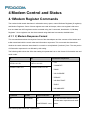
4 Modem Control and Status
4.1Modem Register Commands
The modem holds certain data items in selected memory space, named Software Registers (S-registers)
and Modem Registers. Some of these registers are used as bitmaps, where one register holds more
than one data item.All S-registers can be accessed using the S command, described in “S, Bit Map
Registers”. Some registers can also be accessed using dedicated commands, detailed below.
4.1.1 V, Modem Response Format
This command determines the response format of the data adapter and the contents of the header and
trailer transmitted with the result codes and information responses. This command also determines
whether the result codes are transmitted in a numeric or an alphabetic ("verbose") form. The text portion
of information responses is not affected by this setting.
The following table shows the effect that setting this parameter has on the format of information text and
result codes.
V0
V1
Information Responses
<ATV0><cr><lf>
<ATV1><cr><lf>
<numeric code><cr>
<verbose code><cr><lf>
0 - "OK"
1 - "CONNECT"
2 - "RING"
3 - "NO CARRIER"
4 - "ERROR"
5 - "NO DIALTONE"
6 - "BUSY"
7 - "NO ANSWER"
Command
Syntax
Response/Action
Remarks
Set
ATV<value>
OK
The Set command sets the format
or:
of information responses and result
+CME ERROR: <err>
codes.
The following table shows the V parameters.
<Parameter>
Description
<value>
0
Transmits limited headers and trailers, and numeric text.
1
Transmits full headers and trailers, and verbose response text.
The default value is 1.
Example:
ATV0
0
ATV1
OK
4.1.2 Q, Result Code Suppression
This command determines whether to output the result codes. Information text transmitted in response
to commands is not affected by the setting of this parameter.
Note : For L810, L830, Read command are not supported.
Command
Syntax
Response/Action
Remarks
Set
ATQ<value>
OK
The set commands sets whether or
or:
not to output result codes.
+CME ERROR: <err>
Read
ATQ?
Q: <value>
OK
The following table shows the Qn parameters.
<Parameter>
Description
<value>
0
Transmit result codes.
1
Suppress result codes.
The default value is 0.
Example:
L8-Family AT Commands User Manual
Page 24 of 284
ATQ0
OK
ATQ4
ERROR
ATQ1
// No response because result codes are suppressed.
ATQ4
// No response because result codes are suppressed.
4.1.3 E, Command Echo
This command defines whether input characters are echoed to output. If so, these characters are
echoed at the same rate, parity and format at which they were received.
Note: For L810, L830, ATE? are not supported.
Command
Syntax
Response/Action
Remarks
Set
ATE<value>
OK
The Set command sets whether or
or:
not to echo characters.
+CME ERROR: <err>
Read
ATE?
<value>
OK
The Test command for E is not
defined by ITU, and therefore is not
supported by the Modem. The
Modem returns an error.
The following table shows the E parameters.
<Parameter>
Description
<value>
000
Does not echo characters
001
Echoes characters
The default value is 001.
4.1.4 X, Result Code Selection and Call Progress Monitoring
Control
This command defines the CONNECT result code format. It determines whether or not the Modem
transmits particular result codes to the user. It also controls whether the Modem verifies the presence of
L8-Family AT Commands User Manual
Page 25 of 284
dial tone when it first goes off-hook to begin dialing, and whether the engaged tone (busy signal)
detection is enabled.
Note: For L810, L830, ATX? are not supported.
Command
Syntax
Response/Action
Remarks
Set
ATX<value>
OK
The Set command sets the result code
or:
and call progress monitoring control.
+CME ERROR: <err>
Read
ATX?
<value>
OK
The following table shows the X parameters.
<Parameter>
<value>
Description
0
CONNECT result code given upon entering online data state:
Dial tone detection - Disabled
Busy detection - Disabled
1
CONNECT <text> result code given upon entering online data state:
Dial tone detection - Disabled
Busy detection - Disabled
2
CONNECT <text> result code given upon entering online data state:
Dial tone detection - Enabled
Busy detection - Disabled
3
CONNECT <text> result code given upon entering online data state:
Dial tone detection - Disabled
Busy detection - Enabled
4
CONNECT <text> result code given upon entering online data state:
Dial tone detection - Enabled
Busy detection – Enabled
L8-Family AT Commands User Manual
Page 26 of 284
The default value is 4.
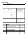
4.1.5 S, Bit Map Registers
This command reads/writes values of the S-registers. The Modem supports this command for various S
values, according to official specifications (ITU-I, ETSI, or manufacturer specific).
Command
Syntax
Response/Action
Remarks
Set
ATSn=<val
OK
The Set command is allowed for
ue>
or:
read/write S-registers, and not
allowed for read-only S-registers.
+CME ERROR: <err>
Read
ATSn?
<current value of
S-register n>
OK
or:
+CME ERROR: <err>
Test
The Test command for Sn is not
defined by ITU, and therefore is not
supported by the Modem. The
Modem returns an error.
The following table shows the different S-registers and their associated values.
Min
Max
Default
Value
Value
Value
Sets/gets number of rings before auto answer.
0
255
0
S2
Sets/gets escape code character.
1
255
43
S3
Sets/gets carriage return code character.
0
127
13
S4
Sets/gets line feed code character.
0
127
10
S5
Sets/gets command line editing character
0
127
8
Sn
Description
S0
(backspace).
L8-Family AT Commands User Manual
Page 27 of 284
S6
Sets/gets the amount of time in seconds, that the
2
10
2
1
255
60
0
255
2
0
255
20
DCE waits between connecting to the line and
dialing, when dial tone is not implemented or
enabled.
S7
Sets the number of seconds in which connection
must be established before the call is
disconnected.
S8
Sets/get the amount of time in seconds, that the
DCE shall pause, during dialing, when a "," dial
modifier is encountered in a dial string.
S12
Sets/get guard time (in units of 50 msec) for the
escape character during CSD connections
Note: S0 (Auto Answer) should work regardless of the DTR HW line state. This is a deviation from the
ITU V. 25-ter standard. For L810, L830, only S0, S4 and S7 are supported.
Example:
ATS0?
000
OK
ATS0=3
OK
ATS0?
003
OK
4.1.6 S2
This command handles the selection of the escape characters, which are stored in S-Register 2, and
specifies the escape character used in CSD connections.
Command
Syntax
Response/Action
Remarks
Set
S2=<esc
OK
The Set command sets the CSD
ape_char
acter>
L8-Family AT Commands User Manual
+CME ERROR: <err>
escape character value if all
parameters are valid.
Page 28 of 284
Read
S2?
<escape_character>
OK
The Read command displays the
currently defined escape character
for CSD connections.
The following table shows the S2 parameters.
<Parameter>
Description
<escape_character>
CSD escape character. Range is 1 to 255.
The default value is 43 ("+").
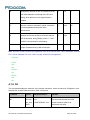
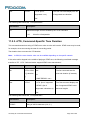
4.1.7 S12
This command handles the selection of the guard time, which is stored in S-Register 12, and specifies
the behavior of escape characters during CSD connection.
Note:
For a guard time specified by S-Register 12, no character should be entered before or after
"+++". The duration between escape codes must be smaller than the guard time.
Command
Syntax
Response/Action
Remarks
Set
S12=<guard
OK
The Set command sets the CSD
_time>
+CME ERROR:
<err>
Read
S12?
<guard_time>
OK
escape character guard time value if
all parameters are valid.
The Read command displays the
current CSD escape character guard
time.
The following table shows the S12 parameters.
<Parameter>
Description
<guard_time>
CSD escape character guard time (units of 50 msec). Range is 0 to
255.
The default value is 20.
4.1.8 &F, Set to Factory Defined Configuration
This command restores the factory default configuration profile. The Modem only supports one factory
L8-Family AT Commands User Manual
Page 29 of 284
default profile, 0.
Note: For L810, L830, Read command are not supported.
Command
Syntax
Response/Action
Set
AT&F<value>
OK
Remarks
or:
+CMS ERROR: <err>
Read
AT&F?
<current profile
number>
Test
The Test command for &F is not
defined by ITU, and therefore is
not supported by the Modem. The
Modem returns an error.
The following table shows the &F parameters.
<Parameter>
Description
<value>
0 Factory default configuration profile. This is the only value supported.
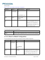
4.1.9 Z, Reset to Default Configuration
This command drops the current call, and resets the values to default configuration.
Command
Syntax
Response/Action
Set
ATZ<value>
OK
Remarks
or:
+CMS ERROR:
<err>
Read
ERROR
The Read command for Z is not defined,
and therefore is not supported by the
Modem. The Modem returns an error.
L8-Family AT Commands User Manual
Page 30 of 284
Test
ERROR
The Test command for Z is not defined,
and therefore is not supported by the
Modem. The Modem returns an error.
The following table shows the Z parameters.
<Parameter>
Description
<value>
0
Set to user profile 0
1
Set to user profile 1
The default value is 0.
Example:
ATZ0
OK
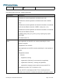
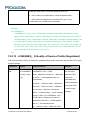
4.1.10 +CRSM, Restricted SIM Access
This command provides limited access to the Elementary Files on the SIM. Access to the SIM database
is restricted to the commands which are listed at <command>. All parameters of AT+CRSM are used as
specified by 3GPP TS 51.011(2G) and TS 31.101(3G). As response to the command, the Modem sends
the actual SIM information parameters and response data. Error result code "+CME ERROR" may be
returned if the command cannot be transferred to the SIM, e.g. if the SIM is not inserted, or defected, or
PIN1/PUK authentication required, or required input parameters not present. However, failure in the
execution of the command in the SIM is reported in <sw1> and <sw2> parameters.
Some of the AT+CRSM commands require PIN/PIN2 authentication.
Note: For L810, L830, Test command only returns OK .
Command
Syntax
Response/Action
Remarks
Set
AT+CRSM=<co
+CRSM:
Set command transmits the
mmand>[,<file_
id>[,<P1>,<P2>
,<P3>[,<data>[,
L8-Family AT Commands User Manual
<sw1>,<sw2>[,<respons
e>]
SIM <command> and its
required parameters to the
ME.
Page 31 of 284
<pathid>]]]]
OK
or:
ME sends the actual SIM
information parameters and
response data.
+CME ERROR: <err>
Test
AT+CRSM=?
+CRSM:
(list of
supported<command>s
The test command returns
the possible ranges of CRSM
Parameters.
),
(possible <file_id>s
range value),(possible
<P1> range value),
(possible <P2> range
value),(possible
<P3>range value),
OK
or:
+CME ERROR: <err>
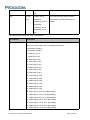
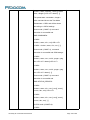
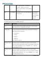
The following table shows the +CRSM parameters.
<Parameter>
Description
<command>
Integer type. Command passed on by the ME to the SIM.
176 Read BINARY
178 Read RECORD
192 Get RESPONSE
214 Update BINARY
220 Update RECORD
242 STATUS
<file_id>
Integer type. This is the identifier of a elementary data file on SIM.
Mandatory for every <command> except of STATUS.
L8-Family AT Commands User Manual
Page 32 of 284
<P1>,<P2>,<P3>
Integer type. Parameters passed on by the ME to the SIM. These
parameters are man- datory for every command, except GET
RESPONSE and STATUS.
READ BINARY
<P1> Offset high (0...255)
<P2> Offset low (0...255)
<P3> Length (0...255)
READ RECORD
<P1> Rec. No. (0...255)
<P2> Mode "02" = next record
"03" = previous record
"04" = absolute mode/current mode, the record number is given in P1
with P1='00' denoting the current record.
<P3> Length (0...255)
GET RESPONSE
<P1> "00"
<P2> "00"
<P3> Length (0...255)
UPDATE BINARY
<P1> Offset high (0...255)
<P2> Offset low (0...255)
<P3> Length (0...255)
UPDATE RECORD
<P1> Rec. No. (0...255)
<P2> Mode "02" = next record
"03" = previous record
"04" = absolute mode/current mode, the record number is given in P1
L8-Family AT Commands User Manual
Page 33 of 284
with P1='00' denoting the current record.
<P3> Length (0...255)
STATUS
<P1> "00"
<P2> "00"
<P3> Length (0...255)
<data>
Information which shall be written to the SIM (hexadecimal character
format). Man- datory for UPDATE BINARY and UPDATE RECORD.
<pathid>
String type; contains the path of an elementary file on the SIM/USIM in
hexadecimal format as defined in ETSI TS 102 221 [60] (e.g.
“7F205F70” in SIM and USIM case).
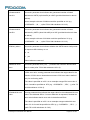
<sw1>
<sw2>
Integer character format. Information, from the SIM, about the execution
of the actual command. These parameters are delivered to the TE in
both cases, on successful or failed execution of the command.
<sw1>, <sw2>
integer type containing the SIM information and can be:
0x90 0x00 normal entry of the command
0x9F 0xXX length XX of the response data
0x92 0x0X update successful but after using an internal retry routine X
times
0x92 0x40 memory problem
0x94 0x00 no EF selected
0x94 0x02 out of range (invalid address)
0x94 0x04 file ID not found; pattern not found
0x94 0x08 file is inconsistent with the command
0x98 0x02 no CHV initialized
0x98 0x04 access cond. Not fullfiled / unsucc. CHV verify
L8-Family AT Commands User Manual
Page 34 of 284
authent.failed
0x98 0x08 in contradiction with CHV status
0x98 0x10 in contradiction with invalidation status
0x98 0x40 unsucc. CHV-verif. Or UNBLOCK CHF / CHV blocked
/UNBL.blocked
0x98 0x50 increases can not be performed. Max. value reached
0x61 0xXX SW2 indicates the number of response bytes still available.
Use GET RESPONSE to access this data.
0x62 0xXX Warning - state unchanged
0x62 0x00 Warning - no information provided
0x62 0x81 Warning - part of returned data may be corrupt
0x62 0x82 Warning - end of file/record reached (bad cmd)
0x62 0x83 Warning - selected file invalidated
0x62 0x84 Warning - bad file control information format
0x63 0xXX Warning - state unchanged
0x63 0x00 Warning - no information provided
0x63 0x81 Warning - file filled up with last write
0x63 0xCx Warning - counter value is x
0x64 0xXX Error - state unchanged
0x65 0xXX Error - state changed
0x65 0x00 Error - no information provided
0x65 0x81 Error - memory failure 66 xx Security Error
0x66 0xXX Security Error
0x67 0xXX incorrect parameter P3
0x68 0xXX Check Error - CLA function not supported
0x68 0x00 Check Error - no information provided
0x68 0x81 Check Error - logical channel not supported
L8-Family AT Commands User Manual
Page 35 of 284
0x68 0x82 Check Error - secure messaging not supported
0x69 0xXX Check Error - command not allowed
0x69 0x00 Check Error - no information provided
0x69 0x81 Check Error - command incompatible with file structure
0x69 0x82 Check Error - security status not satisfied
0x69 0x83 Check Error - authentication method blocked
0x69 0x84 Check Error - referenced data invalidated
0x69 0x85 Check Error - conditions of use not satisfied
0x69 0x86 Check Error - command not allowed (no current EF)
0x69 0x87 Check Error - expected SM data objects missing
0x69 0x88 Check Error - SM data objects incorrect
0x6A 0xXX Check Error - wrong parameters
0x6A 0x00 Check Error - no information provided
0x6A 0x80 Check Error - incorrect parameters in data field
0x6A 0x81 Check Error - function not supported
0x6A 0x82 Check Error - file not found
0x6A 0x83 Check Error - record not found
0x6A 0x84 Check Error - not enough memory space in the file
0x6A 0x85 Check Error - Lc inconsistent with TLV structure
0x6A 0x86 Check Error - inconsistent parameters P1-P2
0x6A 0x87 Check Error - Lc inconsistent with P1-P2
0x6A 0x88 Check Error - referenced data not found
0x6B 0xXX incorrect parameter P1 or P2
0x6C 0xXX Check Error - wrong length - xx is the correct length
0x6D 0xXX unknown instruction code given in the command
0x6E 0xXX wrong instruction class given in the command
0x6F 0xXX technical problem with no diagnostic given
L8-Family AT Commands User Manual
Page 36 of 284
<response>
Response of a successful completion of the command previously issued
(hexadecimal character uppercase format). STATUS and GET
RESPONSE return data, which gives information about the current
elementary data file_id. This information includes the type of file and its
size (refer to GSM 11.11). After READ BINARY or READ RECORD
command the requested data will be returned. <response> is not
returned after a successful UPDATE BINARY or UPDATE RECORD
command.
Example:
AT+CRSM=176,28478,0,0,20
+CRSM: 145,165,"FF"
OK
AT+CRSM=192,12258
+CRSM: 144,0,"62168202412183022FE28A01058B032F06038002000A8800"
OK
AT+CRSM=?
OK
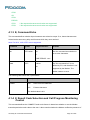
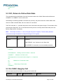
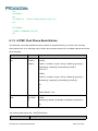
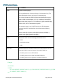
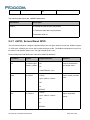
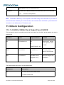
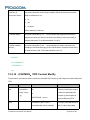
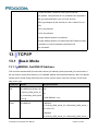
4.1.11 +CCID
This command returns the card identification number in SIM (SIM file EFICCID, see GSM 11.11
Chap.10.1.1) as string type.
Command
Syntax
Response/Action
Set
AT+CCID
+CCID: <ID>
OK
or:
+CME ERROR: <err>
Read
AT+CCID?
L8-Family AT Commands User Manual
Same as above
Page 37 of 284
Test
AT+CCID=?
OK
Example:
AT+CCID
+CCID: 89860018190839008096
OK
AT+CCID=?
OK
AT+CCID?
+CCID: 89860018190839008096
OK
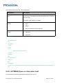
4.2Port Change Commands
The following are the port change AT commands:
GTUSBMODE: Set USB Mode.
The L810, L830, receives a request to change USB mode.
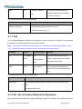
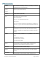
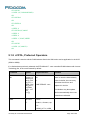
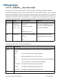
4.2.1 GTUSBMODE, Set USB Mode
This command change the USB mode. The terminal sends +GTUSBMODE=0 or1 or 2,then send
+CFUN=15 to activate the configuration.
Command
Syntax
Response/Action
Set
AT+GTUSBMODE=<m
OK or
ode>
Read
AT+GTUSBMODE?
Remarks
CME ERROR: <error>
+GTUSBMODE :
.Note:user must apply set
<mode>
command first after
OK
download program,or the
read command return
error
Test
AT+GTUSBMODE=?
L8-Family AT Commands User Manual
+GTUSBMODE: (0-2)
Page 38 of 284
OK
Defined values
<mode> indicates the radio access technology and may be
0
3ACM (2 AT+ 1 Trace) and 3NCM
1
MBIM only , end user configuration for Win8+ OS
2
3ACM (2 AT + 1 Trace) and MBIM , for debugging under windows 8+ OS
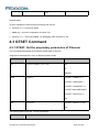
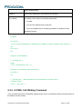
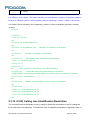
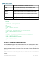
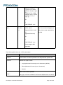
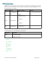
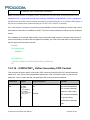
4.3 GTSET Command
4.3.1 GTSET, Set the proprietary parameters of Fibocom
This command set/read/test the proprietary parameters of Fibocom.
*Supported commands list is vary on different product model.
Command
Syntax
Response/Action
Set
+GTSET=<Name>,<P1>,<P2>
OK
or:
ERROR
Read
+GTSET?
+GTSET: "SIMREPO",1
+GTSET: "SIMPHASE",1
+GTSET: "LPMMODE",1,0
+GTSET:"SWCOREDUMP"1
+GTSET: "DIGITPLAY",0
OK
Test
+GTSET=?
+GTSET: "Name",P1<,P2>
OK
The following table shows the +GTSET parameters.
<Parameter>
Description
L8-Family AT Commands User Manual
Page 39 of 284
< Name>
"Name":
parameters name, string.
<P1>
Integer: value according to the “name” parameter
<P2>
Integer: value according to the “name” parameter
Example:
AT+gtset?
+GTSET: "SIMREPO",1
+GTSET: "SIMPHASE",1
+GTSET: "LPMMODE",1,0
+GTSET: "SWCOREDUMP",1
+GTSET: "DIGITPLAY",0
OK
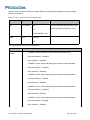
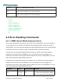
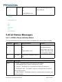
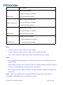
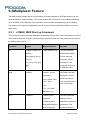
4.4 Error Handling Commands
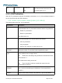
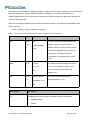
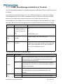
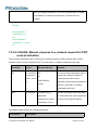
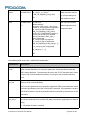
4.4.1 +CMEE, Report Mobile Equipment Error
The Set command disables or enables the use of result code +CME ERROR: <err> as an indication of
an error relating to the functionality of the MODEM. When enabled, Modem -related errors cause a
+CME ERROR: <err> final result code instead of the regular ERROR final result code. Usually, ERROR
is returned when the error is related to syntax, invalid parameters or terminal functionality.
For all Accessory AT commands besides SMS commands, the +CMEE set command disables or
enables the use of result code +CME ERROR: <err> as an indication of an error relating to the
functionality of the Modem. When enabled, Modem related errors cause a +CME ERROR: <err> final
result code instead of the regular ERROR result code.
For all SMS AT commands that are derived from GSM 07.05, the +CMEE Set command disables or
enables the use of result code +CMS ERROR: <err> as an indication of an error relating to the
functionality of the modem. When enabled, modem -related errors cause a +CMS ERROR: <err> final
result code instead of the regular ERROR final result.
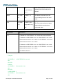
Command
Set
Syntax
AT+CME
E=[<n>]
L8-Family AT Commands User Manual
Response/Action
OK
Remarks
The Set command enables or disables
the use of result code +CME ERROR:
Page 40 of 284
or:
+CME ERROR:
<err>
Read
AT+CME
E?
+CMEE: <n>
OK
<err> as an indication of an error
relating to the functionality of the
Modem.
The Read command returns the
current setting format of the result
code.
Test
AT+CME
+CMEE: (list of
E=?
supported <n>s)
OK
The Test command returns values
supported by the terminal as a
compound value.
The following table shows the +CMEE parameters.
<Parameter>
Description
<n>
0 Disable the +CME ERROR: <err> result code and use ERROR.
1 Enable the +CME ERROR: <err> or +CMS ERROR: <err> result
codes and use numeric <err> values or +STK ERROR: <err> result
codes and use numeric <err> values.
2 Enable the +CME ERROR: <err> or +CMS ERROR: <err> result
codes and use verbose <err> values or +STK ERROR: <err> result
codes and use numeric <err> values.
The default value is 0.
Example:
AT+CMEE=0
//+CME ERROR is not used
OK
AT+VTD
ERROR
AT+CMEE=1
//Use numeric <err>
OK
AT+VTD
+CME ERROR: 1
AT+CMEE=2
//Use verbose <err>
OK
L8-Family AT Commands User Manual
Page 41 of 284
AT+VTD
+CME ERROR: operation not supported
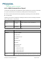
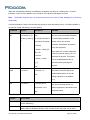
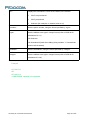
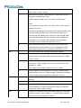
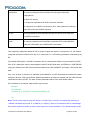
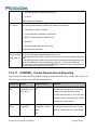
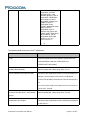
4.4.2 +CEER, Extended Error Report
This execution command returns an extended error report containing one or more lines of information
text <report>, determined by the manufacturer, providing reasons for the following errors:
Failure in the last unsuccessful call setup (originating or answering) or the in-call modification.
Last call release.
Typically, the text consists of a single line containing the reason for the error according to information
given by GSM network, in textual format.
Command
Syntax
Execute
AT+CEER
Response/Action
+CEER: <category>[,<cause>,<description>]
OK
Test
AT+CEER=?
OK
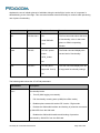
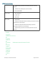
The following table shows the +CEER parameters.
<Parameter>
Description
<category>
“No report available”
“CC setup error”
“CC modification error”
“CC release”
“SM attach error”
“SM detach”
“SM activation error”
“SM deactivation”
“SS – network error cause”
“SS – network reject cause”
“SS – network GSM cause”
<cause>
contains a digit representing the error cause sent by network or internally
L8-Family AT Commands User Manual
Page 42 of 284
<description>
Is a verbose string containing the textual representation of the Cause
5 Call Control
5.1Managing a CSD (Data) Call
The Modem working modes can be divided into two modes of operation.
Data Mode: In this mode, once the MODEM has established a link with the remote modem, it does
not respond to any data passing through it (except for the Escape Sequence search). The Modem
becomes a transparent link, connecting the terminal with the remote side.
Command Mode: In this mode, the Modem responds to the AT commands issued by the terminal.
This is the default working mode.
Note:
It is possible to switch between the operating modes.The operating modes can operate
simultaneously using the MUX and using multi-channels operation.
5.1.1 Simple Dialing
In order to instruct The modem to dial a remote modem from an ordinary tone-dialing telephone line,
enter the Dial command followed by the phone number. For example, type the following command:
ATD 876-5555 <Enter>
Note:
If you receive characters which were sent, you can disable this with using the Echo command
(ATE0 <Enter>).
After issuing the Dial command, and if the remote modem answers the call, the two modems send
high-pitched carrier tones to one another which establish the transmission speed and other parameters
for the data connection. This process is called negotiation.
After the negotiation process, the message, "CONNECT" followed by the connection speed, is received.
If the other phone line is busy, the message “BUSY” is received.
If the other modem does not answer, the message "NO CARRIER" is received.
Once a connection has been established, The modem is ready to immediately begin transmitting and
receiving data. This may vary from sending messages to each other, sending or receiving files, logging
on to an information service, or any other data communication task you wish to perform.
L8-Family AT Commands User Manual
Page 43 of 284
5.1.2 Switching From Data Mode to Command Mode
To switch the connection from Data mode to Command mode, send the Escape Sequence command
(+++).
If The modem responds with "OK" to the Escape command, The modem is in Command mode and the
dial connection is still active, and you can use the AT command set.
Note:
The character '+' in the Escape Sequence pattern can be changed using the S2 S-register.
Escape is detected only by the Modem and not by the remote side. The remote side stays in the
Data mode.
The behavior of Escape Sequence command (+++) is affected by AT&D setting. Please refer to the
description of AT&D.
5.1.3 Hanging Up
If you are using a communications program, use the "Hang up" or "Disconnect" AT command in the
program to disconnect the call.
When using computers in the "Dumb Terminal mode", return to the Command mode by typing the
Escape Sequence (+++) and then hang up by typing the Hang up command as follows:
ATH <Enter>
OK
NO CARRIER
If the Modem responds with "OK" and "NO CARRIER", the dial connection is closed.
5.2Receiving a Data Call
ATA <Enter>
This command instructs The modem to be the "answering modem". Either party may be the answering
or the originating modem, but both parties cannot be the same modem at the same time.
You hear The modem handshake and see the result code "CONNECT" "OK".
Note:
Outgoing Voice Call during CSD Call, when switching to Command mode.
L8-Family AT Commands User Manual
Page 44 of 284
If using Dial Command to make Outgoing Voice Call, currently active CSD Call is dropped and the
new Voice Call is generated.
5.3Call Control AT Commands
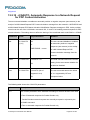
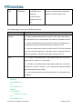
5.3.1 D, Dial Command
This command places a DATA/VOICE call on the current network.
The default call type is a data call (CSD).
There must be an explicit request in order to make a VOICE call.
If a DATA call was originated and answered by the remote side, a "OK" notification is sent to the terminal
from the Modem, and it moves to the online Data state.
For more information about call failure, should use the AT+CEER command.
Note:
If there is an active voice call and the terminal sends another ATD voice call command to the
Modem, the active call is put on hold and the new number is called.
Command
Response/Action
ATD<number>[;]
VOICE CALL:
1st response - Voice call place begins
OK
2nd response - Voice call connected:
OK
DATA:
1st response only - Data call connected
CONNECT
When MO call fails:
1. Connection Failure - NO CARRIER or BUSY or NO ANSWER
2. General Failure - ERROR
3. Security reason (such as SIM not present) - OPERATION NOT
ALLOWED
4. Unknown reason - UNKNOWN CALLING ERROR
L8-Family AT Commands User Manual
Page 45 of 284
The following table shows the D parameters.
<Parameter>
Description
<number>
Valid phone digits are: 0 1 2 3 4 5 6 7 8 9 * # +
The following characters are ignored: A B C D - () / and <space>.
semicolon (;)
When given after <number string>, a voice call is originated to the
given address, otherwise a data call is originated.
The control of supplementary services through the Dial command is not supported as these are
controlled through the specific supplementary service commands (CCFC, CLCK, and so on.)
Initiating a GPRS connection is done through ATD*99#, as described in “D*99”.
Example:
atd44345678;
//VOICE call (with semicolon)
OK
OK
atd44345678
CONNECT
//DATA call (without semicolon)
//Move to online Data state
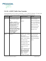
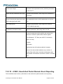
5.3.2 D>, Direct Dialing from Phone Books
This command places a DATA/VOICE call on the current network by dialing directly from the Modem
phone book.
Note:
“+CME ERROR: not found" is returned when no match is found in an existing phone book.
FD phone book supports the (?) wild card character. Telephone numbers containing this character
cannot be dialed directly from the phone book.
"+CME ERROR: Invalid index" is returned when entry <n> is out of the requested Phonebook
range.
The following table shows a detailed description for the D> commands.
Command
Detailed Description
D><alpha>[;]
Originates a call to a phone number with the corresponding
alphanumeric field <alpha>. The Current Phone Book (Set by +CPBS) is
searched for the entry that begins with the alphanumeric pattern
L8-Family AT Commands User Manual
Page 46 of 284
<alpha>.
D>mem<n>[;]
Originates a call to a phone number in memory (phone book) mem and
stored in entry location <n>.
D><n>[;]
Originates a call to a phone number from entry location <n> in the
Current Phone Book (Set by +CPBS).
Note:
Current used memory (phone book) set/read is done through the memory command
+CPBS=/+CPBS? respectively.
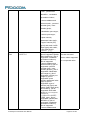
The following table shows the D> parameters.
<Parameter>
Description
<"alpha">
String type value, which should be equal to an alphanumeric field in a
phone book entry. The used character set should be the one selected
with Select Terminal Character Set +CSCS. <alpha> is case-sensitive,
and should be placed in quotes ("alpha").
<n>
This parameter is also called "speed dial location". It is an integer type
memory location. <n> should be in the range of locations available in the
memory used.
<mem>
This parameter is not case-sensitive.
Example:
AT+CPBS="SM"
OK
AT+CSCS="IRA"
OK
AT+CPBW=1,"035659090",129,"VoiceMail"
OK
AT+CPBR=1
+CPBR: 001,"035659090",129,"VoiceMail"
OK
atd>”VoiceMail”;
//Phonebook by name
L8-Family AT Commands User Manual
Page 47 of 284
OK
OK
ath
OK
NO CARRIER
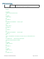
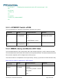
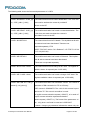
5.3.3 DL, Dial Last Number
The DL command places a voice call to the last number dialed. The call progress information
(success/failure) is reported in the same way as for the Dial command.
Command
Detailed Description
ATDL[;]
Initial Response - Last Number retrieved:
ATDL: <DIAL DIGITS>
1st response - Voice call placement begins
OK
2nd response - Voice call connected OK
The following table shows the DL parameters.
<Parameter>
Description
semicolon (;)
If the semicolon (;) is given, a voice call is originated to the last dialed
number.
If the semicolon (;) is not given, a Data call is originated.
Note: The last dialed call type is irrelevant to the DL command.
Note:
When ATDL is issued after a dialed number with comma digit:
ATDL; (Voice) dials the exact number that was last dialed, including the DTMF tones sent.
If ATDL is sent before any Dial command was issued (mainly after Power On, when the last number
is an empty field), the Modem will return NO CARRIER, as mentioned in the ITU V.25-ter standard.
CCFC(*#21#),CCWA(*#43#),CLIP(*#30#),CLIR(*#31#),COLP(*#76#) will be treat as call number
and dail it again.
Example:
L8-Family AT Commands User Manual
Page 48 of 284
atdl;
ATDL: 035658278
OK
OK
//VOICE call
5.3.4 H, Hang-up Call
This command hangs up a call. The Modem terminates the call whether it is a data or voice call, and
whether it is an incoming, originating, waiting, or connected call.
A NO CARRIER message is returned to the terminal after the regular OK approval.
Note:
To terminate (hang-up) a MO data call while call is placed: Any character sent from the terminal to
the Modem causes the Data call termination, and NO CARRIER is sent from the Modem to the
terminal.
To terminate a held Voice call or to terminate a call out of a MTPY call, refer to “+CHLD, Call
Related Supplementary Services Command”.
The following table shows the call states of the H command.
Call State
Response/Action
IDLE
Error ("operation not allowed")
Single Active
Call released
MTPY Active
Call released (all calls)
Incoming call (RING)
Call released
Single Active and Waiting Call
Single Active released (waiting not
affected)
MTPY Active and Waiting Call
MTPY Active released (waiting not
affected)
Single (or MTPY) Active and Single (or MTPY) Held
Single (or MTPY) Active released
Held (Single or MTPY) and Waiting Call
Waiting call released
Single (or MTPY) Active and Single (or MTPY) Held
Single (or MTPY) Active released
L8-Family AT Commands User Manual
Page 49 of 284
& Waiting call
Example:
RING
//Incoming call
RING
//Incoming call
ath
//Hang-up incoming call
OK
NO CARRIER
//Incoming call has been terminated - user determined user busy
RING
ata
OK
ath
//Voice call connected
//Hang-up connected call
OK
NO CARRIER //Active call has been hung-up - terminated
(... Active multi party call, with 3 numbers …)
ath
OK
NO CARRIER
NO CARRIER
NO CARRIER
atd035659260;
OK
ath
//Terminate MO voice call while placed
OK
NO CARRIER
Example - Hanging up a data call:
atd035659260
CONNECT//Data call connected - Online Data mode
…
+++
//ESC Sequence is sent from the terminal to the Modem
OK
//The Modem is in Command mode
ath
//Terminate Data call
OK
NO CARRIER
L8-Family AT Commands User Manual
Page 50 of 284
5.3.5 A, Answer Incoming Call
This command answers an incoming VOICE/DATA call after a RING/+CRING indication is sent to the
terminal.
If the incoming call is answered (CSD connected), the Modem sends a CONNECT notification to the
terminal.
If the MT call fails, the possible notifications are:
NO CARRIER - Connection Failure
ERROR - General Failure
Note:
A waiting call (an incoming call while a call is in progress) is announced by +CCWA rather than
RING. A waiting call can be answered only if it is a voice call. The waiting voice call should be answered
using the ATA command, which will put the active call on hold and will connect the waiting call, making it
the active call. This ATA action is the same action as AT+CHLD=2.
Example:
Example - Answering a voice call:
AT+CRC=1
+CRING: VOICE
+CRING: VOICE
ata
OK
//VOICE call connected - Modem is in Command mode
ath
OK
NO CARRIER
Example - Answering a data call:
+CRING: REL ASYNC
+CRING: REL ASYNC
ata
...
OK
//Connecting (dots are not displayed)
//DATA call connected - Modem is in Online Data mode
L8-Family AT Commands User Manual
Page 51 of 284
Note:
In a CSD call, call release is not valid during the phase of call negotiation (from OK until connect
call).
5.3.6 +CRC, Cellular Result Codes and RING, +CRING Incoming Call Indication
This command controls whether or not to present the extended format of an incoming call indication. The
RING/+CRING indication is sent from the Modem to the terminal when the Modem is alerted by an
incoming call from the network. Once this indication is sent, information is available on the calling line via
+CLIP. When +CRC is disabled, the indication is RING, and when +CRC is enabled, the indication is
+CRING.
Command
Syntax
Response/Action
Remarks
Set
+CRC=<n
OK
The Set command enables/disables
>
the extended format of an incoming
call indication. When enabled, an
incoming call is indicated to the
terminal with an unsolicited result
code +CRING: <type> instead of the
normal RING.
Read
+CRC?
+CRC: <n>
The Read command queries the
current settings for the cellular result
OK
code.
Test
+CRC=?
+CRC: (list of supported
The Test command returns the
<n>s)
possible <n> values.
RING/+CRING Indication
+CRING: <type>
or:
RING
The following table shows the +CRC parameters.
<Parameter>
Description
<n>
0
Extended format disabled
1
Extended format enabled
L8-Family AT Commands User Manual
Page 52 of 284
The default value is 0.
Type of incoming call:
<type>
asynchronous transparent
ASYNC
[,<priority>[,<subaddr>,<satype>]]
SYNC
synchronous transparent
[,<priority>[,<subaddr>,<satype>]]
REL ASYNC
[,<priority>[,<subaddr>,<satype>]]
asynchronous non-transparent
REL SYNC
[,<priority>[,<subaddr>,<satype>]]
VOICE
synchronous non-transparent
[,<priority>[,<subaddr>,<satype>]]
VOICE/XXX
[,<priority>[,<subaddr>,<satype>]]
normal voice (TS 11)
ALT VOICE/XXX
voice followed by data (BS 81) (XXX is ASYNC,
SYNC,REL SYNC,REL ASYNC)
[,<priority>[,<subaddr>,<satype>]]
alternating voice/data, voice first (BS 61)
GPRS
<PDP_type>,<PDP_addr>[,[<L2P>][,
<APN>]]
VGC
<GCA>, <Gid>, <ackflag>
alternating voice/data, data first (BS 61)
[,<priority>]
VBC
<GCA>, <Gid>, <ackflag>
[,<priority>]
L8-Family AT Commands User Manual
Page 53 of 284
GPRS network request for PDP context activation
voice group call (TS 91)
voice broadcast call (TS 92)
The optional <priority> indicates the EMLPP priority level of the incoming call by paging,
notification or setup message.
<subaddr>: string type subaddress of format specified by <satype>
<satype>: type of subaddress octet in integer format
<PDP_type> ,<PDP_addr> and <APN> are as defined in the Define PDP Context (+CGDCONT)
command. The optional <L2P> proposes a layer 2 protocol to use between the MT and the TE. It is
defined in the Enter GPRS Data Mode (+CGDATA) command. If the MT is unable to announce to
the TE the network’s request (for example it is in V.250 online data state) the MT shall reject the
request. No corresponding unsolicited result code shall be issued when the MT returns to a
command state.
<GCA> is a part of the group call reference and indicates group call area.
<Gid> is a part of the group call reference and indicates group call identification.The <ackflag>=1
proposes that a predefined confirmation procedure is to be used after the call is ended. For
<ackflag>=0 no confirmation procedure is required
Example:
AT+CRC?
+CRC: 0
OK
AT+CRC=?
+CRC: (0-1)
OK
Example - RING/+CRING indication
L8-Family AT Commands User Manual
Page 54 of 284
(..Incoming Data Call..)
RING
RING
RING
AT+CRC=1
//Enable extended ring format
OK
+CRING: REL ASYNC
+CRING: REL ASYNC
ath
OK
AT+CRC=1
OK
+CRING: ALT Voice/Data
NO CARRIER
5.3.7 +CLIP, Calling Line Identification
This command controls the Calling Line Identity (CLI) presentation indication to the terminal when an
incoming call is detected by the Modem.
This command allows the user to query the provisioning status of the CLI by the network and by the
Modem. The command also allows the user to enable/disable the CLI presentation by the Modem to the
terminal.
The +CLIP indication information varies depending on what is provided by the network and what
information is stored in the Modem phone book.
Command
Syntax
Response/Action
Remarks
Set
AT+CLIP=[<n>]
OK
The Set command enables or disables
or:
the presentation of the CLI indication
from the Modem to the terminal.
+CME ERROR:
<err>
Note: The Set command does not
address the network.
Read
AT+CLIP?
+CLIP: <n>, <m>
OK
The Read command returns the +CLIP
enable/disable state in the Modem as
well as in the network provisioning
state of the CLI presentation.
L8-Family AT Commands User Manual
Page 55 of 284
Test
AT+CLIP=?
+CLIP: (0,1)
The Test command returns the Set
OK
command options (0,1).
5.3.8 +CLIP Indication
When the CLI presentation indication is enabled by the Modem (<n>=1), this unsolicited indication is
sent to the terminal after the RING indication.
+CLIP: <number>,<type>[,<subaddr>,<satype>[[,<alpha>] [,<CLI validity>]]]
The following table shows the +CLIP parameters.
<Parameter>
Description
<n>
Enables/disables the CLI presentation indication after the ring indication:
0 Disable CLI presentation
1 Enable CLI presentation
The default value is 0.
<m>
Shows the subscriber CLIP service status in the network:
0 CLIP not provisioned
1 CLIP provisioned
2 Unknown (for example, no network and so on)
<"number">
Calling line number. The number format is specified by <type>.
<type>
Type of address octet in integer format:
145
Default when the dialing string includes the international access
code character "+".
129 Default when making a local call.
128
Type of number is unknown (usually the output when the
number itself is unknown).
<subaddr>
NULL, field not used (String type subaddress of format specified by
<satype>)
<satype>
Field not used. Value is always 128 (unknown) - type of sub address
L8-Family AT Commands User Manual
Page 56 of 284
octet in integer format.
<"alpha">
Name of the calling party (if provided by the network).
<CLI validity>
The Validity of the Calling Line Identity presentation:
0 CLI valid.
1 CLI has been withheld by the originator.
2 CLI is not available due to networking problems or limitations of the
originating network.
Example:
AT+CLIP=?
+CLIP: (0,1)//CLI presentation is disabled by the Modem (0) and is enabled by the network (1)
OK
AT+CLIP=1
OK
Example +CLIP indication:
(…incoming call…)
RING
+CLIP: "13510503472",129,,,"",0
Example +CLIP indication with restricted CLI:
AT+CRC=1
OK
(…incoming call…, caller restricted the CLI presentation (used AT+CLIR)…)
+CRING: VOICE
+CLIP: "",128,,128,"",1
5.3.9 +CCWA, Call Waiting Command
This command controls the Call Waiting supplementary service, including the settings and the queries of
the Modem and the network.
L8-Family AT Commands User Manual
Page 57 of 284
When the Call Waiting indication is enabled by the Modem and there is a waiting call, a +CCWA:
indication is sent from the Modem to the terminal. The indication will appear one time
Note:
The Modem supports only one of the services at a time: Voice or Data. Multiparty is a voice-only
functionality.
A CCWA indication is sent to the terminal only during a voice call-waiting event. A CCWA indication is
not sent for a data call during in a voice session.
Command
Syntax
Response
Remarks
Set
+CCWA=[<n>[,<
OK
The Set command enables/disables
If <mode>=2 and the
the Call-Waiting indication in the
command succeeds:
Modem and in the network.
mode>[,<class>]]
]
+CCWA:
Activation, deactivation and status
query are supported.
<status>,<class>[<C
R><LF>
Note: When the <mode> parameter
is set to 2 (network query), the <n>
+CCWA:
<status>,<class>
Read
+CCWA?
parameter is ignored. This means
that no enable/disable action is
[...]]
performed while querying the
OK
network.
+CCWA: <n>
The Read command returns the
OK
enable/disable status of the call
waiting indication in the Modem
(<n>).
Test
+CCWA=?
+CCWA: (list of
supported <n>s)
OK
The Test command returns <n>
values supported by the Modem as a
compound value.
The following table shows the <class> parameters.
<Class>
Description
1
Voice (telephony)
2
data (refers to all bearer services; with <mode>=2 this may refer only to some
L8-Family AT Commands User Manual
Page 58 of 284
bearer service if TA does not support values 16, 32, 64 and 128)
4
Fax (facsimile services)
8
short message service
16
data circuit sync
32
data circuit async
64
dedicated packet access
128
dedicated PAD access
5.3.10 +CCWA Indication
When a call-waiting indication is enabled by the Modem (<n>=1), the following unsolicited indication is
sent to the terminal from the Modem:
+CCWA: <number>,<type>,<class>[,<alpha>] [,<CLI validity>]
The following table shows the +CCWA parameters.
<Parameter>
Description
<n>
Enables/disables the call waiting indication to the terminal by the Modem.
0 - Disable
1 - Enable
The default value is 0.
<mode>
Call waiting service request to the network. When the <mode> parameter
is not given, the network is not interrogated.
0 - Disable
1 - Enable
2 - Query status
<class>
Sum of integers each representing a class of information.
Please see class table in +CCWA command.
The default value is 7.
L8-Family AT Commands User Manual
Page 59 of 284
<number>
Calling line number. The number format is specified by <type>.
<type>
Type of address octet in integer format:
145 - Default when the dialing string includes the international access
code character "+".
129 - Default when making a local call.
128 - Type of number is unknown (usually the output when the number
itself is unknown)
<status>
Call waiting support by the network (output for <mode>=2).
0 - Not active
1 - Active
<alpha>
Name of the calling party (if provided by the network).
<CLI validity>
The Validity of the Calling Line Identity presentation:
0 - CLI valid.
1 - CLI has been withheld by the originator.
2 - CLI is not available due to networking problems or limitations of the
originating network.
Note:
When the parameter <mode> is 2 (Query status), the first parameter is ignored and the third
parameter is always treated as class = 1 unless it was set in Set Mode.
Example:
AT+CCWA=1
OK
AT+CCWA=?
+CCWA: (0,1)
OK
AT+CCWA?
+CCWA: 1
L8-Family AT Commands User Manual
Page 60 of 284
OK
Examples of +CCWA set command - network interrogation
AT+CCWA=1,2
+CCWA: 1,1
//Class parameter is considered as 7
//Call waiting is active for class 1, voice
OK
AT+CCWA=1,2,2 //Class parameter is 2
+CCWA: 0,2
//Call waiting is not active for class 2, data
OK
AT+CCWA=1,1
OK
//Enable the call waiting feature in the network,
Example +CCWA indication
atd9311234567;
//Originate a voice call
OK
OK
//Voice call connected
(...conversation...)
+CCWA: "+358317654321",145,1,"Bob"
AT+CHLD=0
//Release the waiting call
OK
NO CARRIER
AT+CRC=1
//RING indication is not relevant to CCWA indication
OK
(…waiting call…, caller restricted to its CLI presentation (used AT+CLIR)…)
+CCWA: "",128,1,"",1
//CLI is restricted, but call type recognized as voice
5.3.11 +CHLD, Call Related Supplementary Services Command
This command controls the Call Hold and Multiparty Conversation services. This command manipulates
voice calls only. The Set command allows the control of the following call related services:
Call HOLD: A call can be temporarily disconnected from the Modem, but the connection is retained
by the network.
MTPY (Multi party) Conversation: Conference calls.
The network does not reserve more than one traffic channel for a mobile station, therefore the Modem
can have only one call on hold at a time.
Note:
Only voice calls can be put on HOLD.
A precondition for the multi-party service is that the Modem is in control of one active call and one call on
hold. In this situation, the Modem can request the network to begin the MTPY (Multi Party) service. Once
L8-Family AT Commands User Manual
Page 61 of 284
a MTPY call is active, remote parties may be added, disconnected or separated (removed from the
MTPY call, but remain connected to the served mobile subscriber).The maximum number of remote
parties is 5.
In this command, the term CALL refers to a single or MTPY call.
A single Active call is considered a MTPY call with one call index numbered as 1.
Command
Response/Action
+CHLD=<n>
If the call is terminated:
OK (approve request was submitted)
NO CARRIER
If the call state is changed (link, split, from active to hold, and so on):
OK (approve request was done)
If the call is terminated and another call is answered
OK (call answered and is now connected)
NO CARRIER
Command
Syntax
Response/Action
Remarks
Test
+CHLD
+CHLD: (list of supported
The Test command returns <n>
=?
<n>s)
values supported by the Modem to
OK
the terminal
The following table shows the +CHLD parameters.
Parameter n
Description
0
Release all held calls or set User Determined User Busy for a
waiting\incoming call; if both exists then only the waiting call will be rejected.
1
Releases all active calls and accepts the held or waiting call
Note: In the scenario: An active call, a waiting call and held call, when the
active call is terminated, we will make the Waiting call as active.
1x
Release a specific call (x specific call number as indicated by +CCLC)
L8-Family AT Commands User Manual
Page 62 of 284
2
Place all active calls (if exist) on hold and accepts the other call (held or
waiting\incoming). If only one call exists which is active, place it on hold and
2x
if only held call exists make it active call
Place all active calls on hold except call x with which communication is
3
supported
Adds a held call to the conversation
4
Connects the two calls and disconnects the subscriber from both calls
6
(Explicit Call Transfer)
Puts an active call on hold or an held call to active, while another call is
waiting
7
Disconnect users in multiparty without accepting incoming call
8
release all calls
Example:
AT+CHLD=?
+CHLD: (0,1,1x,2,2x,3,4,6,7,8)
OK
AT+CCWA=1
//Enable call waiting
OK
atd9311234567;
//Originate a voice call
OK
OK (...conversation...)
+CCWA: "+358317654321 ",145,1,"Bob"
AT+CHLD=2
//Awaiting call alerts
//Put first call on hold and answer the second call
OK (...conversation...)
AT+CHLD=3
//Add the held call to the conversation
OK
(...MTPY conversation...)
AT+CHLD=22
//Split: Place the MO active call on hold, MT call remains active
OK
AT+CHLD=0
//Release the held call
OK
NO CARRIER
ath
//Release the active call
OK
NO CARRIER
atd9311234567;
//Originate a voice call
L8-Family AT Commands User Manual
Page 63 of 284
OK
OK
+CCWA: "055728386",129,1," ",0 //Waiting call alerts
AT+CHLD=1
//Release the active call, accept the waiting call
OK
NO CARRIER
OK
//Active 9311234567 was released
//Waiting 055728386 was answered
5.3.12 +CCFC, Call Forwarding Number and Conditions
This command enables control of the call-forwarding supplementary service. Registration, erasure,
activation, deactivation, and status query are supported.
Command
Syntax
Response/Action
Set
+CCFC=<reason
If the command succeeds:
>,<mode>[,<num
ber>[,<type>[,<cl
ass>[,<subaddr>[
,<satype>[,<time
+CCFC:
<status>,<class>[,<number>,<typ
e>[,<subaddr>,<satype>[,<time>]]
] [<CR><LF>
Remarks
The Set command
instructs the Modem
which call forwarding
settings to request from
network. The Set
>]]]]]]
+CCFC:
<status>,<class>[,<number>,<typ
e>[,<subaddr>,<satype>[,<time>]]
][...]]
+CCFC: (list of supported
command, in query
mode, interrogates the
network about the
subscriber current call
forwarding status.
<reason>s)
Test
+CCFC=?
+CCFC: <reason>
OK
The Test command
returns <reason> values
supported by the
Modem to the terminal.
The following table shows the +CCFC parameters.
<Parameter>
Description
<reason>
0 - Unconditional
L8-Family AT Commands User Manual
Page 64 of 284
1 - Mobile busy
2 - No reply
3 - Not reachable
4 - All call forwarding
5 - All conditional call forwarding
<mode>
0 - Disable
1 - Enable
2 - Query status
3 - Registration
4 - Erasure
<number>
Calling line number. The number format is specified by <type>.
<type>
Type of address octet in integer format-.
145 Default when dialing string includes international access code character "+".
129 Default when making a local call.
<subaddr>
NULL, field not used (String type subaddress of format specified by <satype>).
<satype>
Field not used. Value is always 128 (unknown) - type of sub address octet in
integer format.
<class>
The sum of integers, each representing a class of information.
Please see class table in +CCWA command.
The default value is 7.
<time>
1-30 - The number of seconds to wait before calls are forwarded, when "no
reply" is enabled or queried.
The default value is 20.
Note: The parameter must be a multiple of 5, for example, 5, 10, 15 and so on.
<status>
0 - Not active
L8-Family AT Commands User Manual
Page 65 of 284
1 - Active
Note:
A forward-to phone <number> (and the optional fields <type>, <subaddr> and <satype>) are tied
to a <reason> and a <class>. This means that there can be a different <number> for the same <reason>
because of a different <class>. When registering without mentioning a <class>, <class>=7 is selected.
A <number> field is mandatory when registering (<mode>=3) and it is irrelevant (ignored) in all other
<mode>s.
Example:
AT+CCFC=?
+CCFC: (0,1,2,3,4,5)
OK
AT+CCFC=0,3,"01256316830",129,1
OK
AT+CCFC=1,3,"0545658278",129,1
//Register UC forward-to of all classes.
OK
AT+CCFC=1,1
//Activate UC forward-to of all classes.
OK
AT+CCFC=1 ,2
//Interrogate reason not-reachable of all classes.
+CCFC: 1,1,"+97254151200",145
+CCFC: 0,2,"",0
+CCFC: 0,4,"",0
OK
//For <reason>=3, forward only voice calls is activated.
AT+CCFC=4,2
//Interrogate reason all-call-forwarding for all classes.
+CME ERROR: no network service//Interrogation of <reason>=30 is not supported by network.
AT+CCFC=2,3,"+972545658278"
OK
AT+CCFC=2,0
//Disable call-forwarding for reason no-reply of all classes.
OK
AT+CCFC=2,2
+CCFC: 0,1,"+972545658278",145,,25
+CCFC: 0,2,"+972545658278",145,,25
+CCFC: 0,4,"+972545658278",145,,25
OK
5.3.13 +CLIR, Calling Line Identification Restriction
This command instructs the Modem to query, enable or disable the presentation of the CLI (calling line
ID) of a MO call to the called party. The restriction of the CLI (disable presentation) is dependent both on
L8-Family AT Commands User Manual
Page 66 of 284
the Modem and on the network.
The network enables three possible provisions of CLIR:
Not provisioned (CLIR Off - presentation allowed)
Provisioned permanently
Provisioned with Temporary mode
The provision is fixed and cannot be changed by an AT command. Temporary Mode:
Temporary mode can be in one of two states:
A - Presentation restricted (CLIR On) as default.
B - Presentation allowed (CLIR Off) as default. A subscriber to Temporary mode always has a
default subscription to state A or B. Temporary-mode provisioning means that the terminal can
request the Modem to switch the default mode from A to B, and vice versa.
Note:
When a service is in state A, and the terminal wants to enable the CLI presentation (turn CLIR
off) for a single call, it can do so using the ATD command. This does not change the Temporary mode
state. This can also be done when the service is in state B and the terminal wants to disable the CLI
presentation (turn CLIR on) for a single call.
Command
Syntax
Response/Action
Remarks
Set
+CLIR=<n
OK
The Set command instructs the
>
or:
Modem to enable/disable CLI
restriction for all MO calls.
+CME ERROR: <err>
Read
+CLIR?
+CLIR: <n>,<m>
OK
The Read command returns the
current setting of CLIR on the network
<m> and on the Modem <n>.
Test
+CLIR=?
+CLIR: (list of
The Test command returns <n> values
supported<n>s)
supported by the Modem.
The following table shows the +CLIR parameters.
<Parameter>
Description
<n>
Adjustment for outgoing calls
0 - Presentation indicator is used according to the subscription of the
L8-Family AT Commands User Manual
Page 67 of 284
CLIR service
1 - CLIR invocation
2 - CLIR suppression
The default value is 2.
<m>
Subscriber CLIR service status in the network
0 - CLIR not provisioned
1 - CLIR provisioned in permanent mode
2 - Unknown (for example, no network and so on)
3 - CLIR Temporary mode presentation restricted (can be the default)
4 - CLIR Temporary mode presentation allowed (can be the default)
Example:
AT+CLIR=?
+CLIR: (0-2)
OK
AT+CLIR?
+CLIR: 0,0
AT+CLIR=2
OK
atd054565195;
//MO voice call
OK
(… calling …)
(… a Modem that has 054565195 SIM and is CLIP enabled will receive the following on the
terminal:
RING
+CLIP: "",128,,128,"",1
RING
+CLIP: "",128,,128,"",1)
ath
NO CARRIER
OK
AT+CLIR=0
L8-Family AT Commands User Manual
Page 68 of 284
OK
atd054565195;
//MO voice call
OK
(… calling …)
(… a Modem that has 054565195 SIM and is CLIP enabled will receive the following on the
terminal:
RING
+CLIP: "054565006",129,,128," ",0
RING
+CLIP: "054565006",129,,128," ",0 …)
ath
OK
NO CARRIER
5.3.14 +CBST, Select Bearer Service Type
This command sets the bearer service (data circuit duplex asynchronous and synchronous). It chooses
one of the bearer services, the data rate of the service (actually the modulation when modem IWFs are
used), and enables or disables the Radio Link Protocol.
Command
Syntax
Response/Action
Remarks
Set
AT+CB
OK
The Set command selects the bearer
ST=[<s
+CME ERROR:
service <name> with data rate
peed>[,
<err>
<speed> and the connection element
<name
<ce> to be used when data calls are
>[,<ce>]
originated (refer to GSM 02.02).
]]
Values may also be used during
mobile terminated data call setup,
especially in the case of single
numbering scheme calls.
Note: For incoming calls, the bearer
service will be taken automatically
from incoming parameters and not
according to the CBST Set command.
The Modem does not change the
output, but for incoming calls, the
phone works in automatic mode.
Read
AT+CB
+CBST:
ST?
<speed>,<name>,
L8-Family AT Commands User Manual
Page 69 of 284
<ce>
OK
Test
AT+CB
+CBST: (list of
The Test command returns values
ST=?
supported
supported by the MA as compound
<speed>s), (list of
values.
supported
<name>s), (list of
supported <ce>s)
OK
The following table shows the +CBST parameters.
<Parameter>
Description
<speed>
0 - Auto-baud (automatic selection of the speed; this setting is possible in
case of 3.1 kHz modem and non-transparent service)
4 -2400 bps (V.22bis)
5 -2400 bps (V.26ter)
6 - 4800 bps (V.32)
7 - 9600 bps (V.32)
12 -9600 bps (V.34)
14 -14400 bps (V.34)
15 -19200 bps (V.34)
16 -28800 bps (V.34)
17 -33600 bps (V.34)
39 -9600 bps (V.120)
43 -14400 bps (V.120)
47 -19200 bps (V.120)
48 -28800 bps (V.120)
49 -38400 bps (V.120)
50 -48000 bps (V.120)
51 -56000 bps (V.120)
68 -2400 bps (V.110 or X.31 flag stuffing)
70 - 4800 bps (V.110 or X.31 flag stuffing)
71 - 9600 bps (V.110 or X.31 flag stuffing)
75 -14400 bps (V.110 or X.31 flag stuffing)
79 -19200 bps (V.110 or X.31 flag stuffing)
80 -28800 bps (V.110 or X.31 flag stuffing)
81 -38400 bps (V.110 or X.31 flag stuffing)
L8-Family AT Commands User Manual
Page 70 of 284
82 -48000 bps (V.110 or X.31 flag stuffing)
83 -56000 bps (V.110 or X.31 flag stuffing; this setting can be used in
conjunction with asynchronous non-transparent UDI or RDI service in
order to get FTM)
84 -64000 bps (X.31 flag stuffing; this setting can be used in conjunction
with asynchronous non-transparent UDI service in order to get FTM)
115 -56000 bps (bit transparent)
116 -64000 bps (bit transparent)
120 -32000 bps (PIAFS32k)
121 -64000 bps (PIAFS64k)
130 -28800 bps (multimedia)
131 -32000 bps (multimedia)
132 -33600 bps (multimedia)
133 -56000 bps (multimedia)
134 -64000 bps (multimedia)
The default value is 7.
<name>
0 - Data circuit asynchronous (UDI or 3.1 kHz modem)
The default value is 0.
1 - data circuit synchronous (UDI or 3.1 kHz modem)
4 - data circuit asynchronous (RDI)
5 - data circuit synchronous (RDI)
<ce>
0 - Transparent
1 - Non-transparent (default)
2 - both, transparent preferred
3 - both, non-transparent preferred
Example:
AT+CBST=?
+CBST: (0,4-7,12,14-17,68,70-71,75,79-84,115-116,120-121,130-134),(0-1,4-5),(0-3)
OK
AT+CBST?
+CBST: 7,0,1
OK
AT+CBST=6
OK
AT+CBST?
L8-Family AT Commands User Manual
Page 71 of 284
+CBST: 6,0,1
OK
5.3.15 O, Return to Online Data State
This command returns the Modem from the Command mode to the Online Data mode and issues a
CONNECT or CONNECT <text> result code.
After dialing or answering (atd/ata commands and connect), the phone enters the Online Data mode
where it is able to transfer data, but not to enter AT commands.
The ESC command +++, transfers the phone to the Command mode (able to input AT commands, while
preserving the Data call). The O command returns the phone to the fully Online Data mode (as it was
before using the ESC command).
Note:
The escape character '+' can be changed using the S2-register. The time delay between
consecutive escape characters is configured using the S 12-register.
Command
Syntax
Response/Action
Execute
ATO
CONNECT
+CME ERROR: <err> If phone is not in Data Call
NO CARRIER: If connection is not successfully resumed.
Example:
ATD035684072
CONNECT
//Calling a remote modem - data call
//Modem is in Data mode
//Escaping back to Command mode using the +++ sequence
OK
AT
//Modem is in Command mode
OK
ATO
//Returning to Data mode
CONNECT
5.3.16 +CHUP, Hang Up Call
This command causes the Modem to hang up the current call.
Command
Syntax
L8-Family AT Commands User Manual
Response/Action
Remarks
Page 72 of 284
Set
+CHUP
OK
or:
The Set command hangs up the
current GSM call.
+CME ERROR <err>
Example:
atd15986784172;
OK
OK
At+CHUP
OK
NO CARRIER
5.4Call Status Messages
5.4.1 +CPAS, Phone Activity Status
This command displays the current activity status of the Modem; like call in progress, or ringing.
Command
Syntax
Response/Action
Remarks
Execute/Re
AT+CPAS
+CPAS: <pas>
The Execute and Read
OK
commands return the
or:
activity status <pas> of the
+CME ERROR: <err>
Modem. They can be used
ad
to interrogate the Modem.
Test
AT+CPAS
+CPAS: (list of supported <pas>s)
=?
OK
The following table shows the +CPAS parameters.
<Parameter>
Description
<pas>
0 - Ready - The Modem allows commands from the terminal
1 - unavailable(MT does not allow commands from TA/TE)
2 - Unknown - The Modem is not guaranteed to respond to instructions
3 - Ringing (MT calls) - The Modem is ready for commands from the terminal,
but the ringer is active
4 - Call in progress - The Modem is ready for commands from the terminal, but a
call is in progress
L8-Family AT Commands User Manual
Page 73 of 284
5 - asleep(MT is unable to process commands from TA/TE because it is in a low
functionality state)
Example:
AT+CPAS
+CPAS: 0
OK
AT+CPAS=?
+CPAS: (0-5)
OK
//AT+CPAS?
//+CPAS: 4
//OK
AT+CPAS//Voice call active state
+CPAS: 4
OK
5.4.2 +CLCC, List Current Calls
This command displays a list of all current Modem calls and their statuses, and also enables/disables
the unsolicited indication of the call list. (If no calls are received, no information response is sent to the
terminal.)
If the command succeeds but no calls are available, no information response is sent to the terminal.
The maximum number of simultaneous multiparty calls is 5+1 (5 in active group and 1 on hold).
Note: For L810, L830, at+clcc? are not supported now.
Command
Syntax
Response/Action
Remarks
Set
AT+CLC
OK
The Set command
C=<state
or:
enables/disables
>
+CME ERROR: <err>
unsolicited indications.
AT+CLC
+CLCC: <idx>,<dir>,<call state>,
The Execute command
C
<mode>,<mpty>,<number>,<typ
enables the receiving
e> [<CR><LF>
of data about current
+ CLCC: <idx>,<dir>,<call
calls.
Execute
state>,<mode>,<mpty>,<number
>,<type>
[…]]
L8-Family AT Commands User Manual
Page 74 of 284
OK
Read
AT+CLC
+CLCC: <state>
The Read command
C?
OK
returns the call status.
or:
+CME ERROR <err>
Test
AT+CLC
+CLCC: (List of supported
C=?
<state>s)
OK
or:
+CME ERROR <err>
The following table shows the +CLCC parameters.
<Parameter>
Description
<state>
0
Disable CLCC unsolicited indication
1
Enable CLCC unsolicited indication
<idx>
Integer type, call identification number
<dir>
0
Mobile originated call (MO)
1
Mobile terminated call (MT)
<call state>
<mode>
The default value is 0.
The state of the call
0
Active
1
Held
2
Dialing (MO call)
3
Alerting (MO call)
4
Incoming (MT call)
5
Waiting (MT call)
6
Released
Bearer/Teleservice
0
Voice Call
1
Data
L8-Family AT Commands User Manual
Page 75 of 284
<mpty>
<number>
3
Voice followed by data, voice mode
9
Unknown
Multiparty status
0
Call is not part of a multiparty call
1
Call is one of multiparty call parties
Phone number in the format specified by <type>.
Contains a string of up to 32 characters.
<type>
Phone number display format.
Type of address octet in integer format (refer to GSM 04.08 subclause
10.5.4.7)
129 Local number
145 International number with access character +
Note:
When a mobile-originated call is routed to PSTN (PABX), no ALERT indication is prompted.
Example:
AT+CLCC=?
+CLCC: (0,1)
OK
AT+CLCC
+CLCC: 1,0,0,0,0,"01256316830",129
OK
5.5Call Advice of Charge Commands
This set of commands enables GSM operators to offer Advice of Charge (AoC) services that calculate
call charges. These charges are expressed in terms of home units.
5.5.1 +CAOC, Advice of Charge
This command displays information about the cost of calls. If supported, this command also
activates/deactivates unsolicited event reporting of the CCM (Current Call Meter) information.
L8-Family AT Commands User Manual
Page 76 of 284
The unsolicited report +CCCM: <ccm> is sent when the CCM value changes, but not more than once
every 10 seconds.
Note:
The CCM value depends on the network properties (charge for MO or/and MT calls).
There are two states in which the command can be activated:
In IDLE state - returns the last call cost.
A voice/data state - returns the accumulated cost, including the current call.
Command
Syntax
Response/Action
Remarks
Set
+CAOC[=<mod
[+CAOC: <ccm>]
The Set command returns the CCM
e>]
OK
value from the Modem, or
activates/deactivates unsolicited
or:
reports.
+CME ERROR: <err>
Read
+CAOC?
+CAOC: <mode>
+CAOC
OK
The Read command returns the
current CAOC mode.
or:
[+CAOC: <ccm>]
or:
+CME ERROR: <err>
Test
+CAOC=?
+CAOC: (list of
The Test command returns the
supported <mode>s)
supported mode values.
OK
The following table shows the +CAOC parameters.
<Parameter>
Description
<mode>
0
Queries the CCM value
1
Deactivates unsolicited reporting of the CCM value
2
Activates unsolicited reporting of the CCM value
Note:
<CCM>: String type value representing three bytes of the current call meter value in
hexadecimal format (for example, "00001E" indicates decimal value 30).
L8-Family AT Commands User Manual
Page 77 of 284
Example:
Example with prepaid SIM card with 56700.00L prepaid before the test.
AT
OK
AT+CAOC=2
OK
atd+97254565190;
OK
OK
+CCCM: "000000"
+CCCM: "000006"
AT+CAOC
+CAOC: "000009"
OK
+CCCM: "00000e"
+CCCM: "000016"
AT+CAOC
+CAOC: "00001d"
OK
+CCCM: "00001e"
+CCCM: "000027"
AT+CAOC=0
+CAOC: "00002d"
OK
AT+CAOC=2
OK
+CCCM: "00003d"
AT+CAOC
+CAOC: "00003f"
OK
+CCCM: "000046"
AT
+CCCM: "00004e"
+CAOC
+CAOC: "00004f"
OK
L8-Family AT Commands User Manual
Page 78 of 284
+CCCM: "000056"
AT+CAOC
+CAOC: "00005d"
OK
+CCCM: "00005e"
NO CARRIER
AT+CAOC
+CAOC: "000066"
OK
//567 (prepaid SIM value) - 102 (price per call unit by provider) x 66 (call units) = 465 left in prepaid
SIM
OK
There is now 46500.00L prepaid remaining on the SIM card.
Note:
The above example shows first time activation of the AOC feature using the Modem. Therefore,
the accumulated cost is equal to the current call cost.
5.5.2 +CACM, Accumulated Call Meter
This command resets the Advice of Charge accumulated call meter value in the SIM file, EFACM. ACM
contains the total number of home units for both the current call and preceding calls.
Command
Syntax
Response/Action
Remarks
Set
+CACM
OK
The Set command resets the
+CME ERROR:
accumulated call meter value. SIM
<err>
PIN2 is required.
=<pass
wd>
Read
+CACM
+CACM: <acm>
The Read command displays the
?
+CME ERROR:
current value of ACM.
<err>
Test
+CACM
OK
=?
The Test command indicates whether
the +CACM command is functioning.
The following table shows the +CACM parameters.
<Parameter>
Description
<passwd>
SIM PIN2 password
L8-Family AT Commands User Manual
Page 79 of 284
Maximum string length is 8 characters. If this value is exceeded, the
command terminates in an error. If PIN2 is incorrect, "+CME ERROR:
incorrect password" is displayed.
<acm>
Accumulated call meter maximum value (similar to CCM; Refer to
“+CAOC, Advice of Charge”).
The default value is 0.
<ccm> String type; three bytes of the current call meter value in
hexadecimal format (for example, 00001E indicates a decimal value of
30). Value is given in home units; bytes are similarly coded as the
ACMmax value in the SIM.
Example:
AT+CACM=?
OK
AT+CACM?
+CACM: "000000"
OK
AT+CACM="2222"
OK
5.5.3 +CAMM, Accumulated Call Meter Maximum
This command sets the Advice of Charge accumulated call meter maximum value in the SIM file,
EFACM max. ACM max contains the maximum number of home units the subscriber is able to consume.
When the ACM (Refer to “+CACM, Accumulated Call Meter”) reaches ACM max, additional calls
(mobile-originated and mobile-terminated calls that incur charges) are prohibited, except for emergency
calls. Refer to GSM 02.24.
Command
Syntax
Response/Action
Remarks
Set
+CAMM
OK
The Set command sets the
=[<acm
_max>,
<passw
d>]
+CME ERROR:
<err>
accumulated call meter maximum
value. SIM PIN2 is required. The value
that is set remains after a power cycle.
Note: This command is activated if
Advice of Charge is supported by the
L8-Family AT Commands User Manual
Page 80 of 284
network.
Read
+CAMM
+CAMM:
?
<acmmax>
The Read command displays the
current value of ACMmax.
OK
Test
+CAMM
OK
=?
The Test command indicates whether
the +CAMM command is functioning.
The following table shows the +CAMM parameters.
<Parameter>
Description
<acmmax>
Accumulated call meter maximum value (similar to CCM; Refer to
“+CAOC, Advice of Charge”)
<ccm> String type; three bytes of the current call meter value in
hexadecimal format (for example, 00001E indicates a decimal value of
30). Value is given in home units; bytes are similarly coded as the
ACMmax value in the SIM.
Range is from 00001 to FFFFFF.
0
<passwd>
Disables ACMmax (default)
SIM PIN2 password
Maximum string length is 8 characters. If this value is exceeded, the
command terminates in an error. If PIN2 is incorrect, "+CME ERROR:
incorrect password" is displayed.
Example:
AT+CAMM=?
OK
AT+CAMM="FFFFFF","2222"
OK
AT+CAMM?
+CAMM: "FFFFFF"
OK
L8-Family AT Commands User Manual
Page 81 of 284
5.5.4 +CPUC, Price per Unit and Currency Table
This command sets the parameters of the Advice of Charge-related price per unit and currency table
found in the SIM file, EFPUCT. PUCT information is used to convert the home units (used in +CAOC,
+CACM and +CAMM) into currency units.
Command
Syntax
Response/Action
Set
+CPUC=
OK
<currenc
y>,<ppu>
unit and the currency table. SIM PIN2
<err>
is required. The new value is retained
after a power cycle.
>
Test
+CPUC?
+CPUC=
The Set command sets the price per
+CME ERROR:
,<passwd
Read
Remarks
+CPUC:
The Read command displays the
<currency>,<ppu>
current price per unit and currency
OK
table.
OK
The Test command indicates whether
?
the +CPUC command is functioning.
The following table shows the +CPUC parameters.
<Parameter>
Description
<currency>
Currency code character set (3 characters) defined by +CSCS
command. (Refer to “+CSCS, Select Terminal Character Set”)
If the string begins with an alphanumeric character, it may be entered
with or without quotation marks, for example, "GBP", "DEM".
<ppu>
Price per unit A dot is used as a decimal separator (precision of 1/1000;
15 digit maximum), for example,"2.667". [See notes below]
<passwd>
SIM PIN2 password Maximum string length is 8 characters. If this value
is exceeded, the command terminates in an error. If PIN2 is incorrect,
"+CME ERROR: incorrect password" is displayed.
Example:
AT+CPUC=?
OK
L8-Family AT Commands User Manual
Page 82 of 284
AT+CPUC="GBP","0.125","2222"
OK
AT+CPUC?
+CPUC: "GBP","0.125"
OK
Note:
If <ppu> contains a dot, a maximum of three digits may appear after the dot, otherwise an error is
generated. For example, if <ppu>=0.61, the Read command displays 0.610. <ppu>=1 .2345
terminates in an error.
If <ppu> does not contain a dot, the number is divided by 1000. For example, if <ppu>=1, the Read
command displays 0.001.
Due to storage constraints, the <ppu> value is limited to a range of 0 to 4095. Values beyond this
range may result in rounding errors. For example, if <ppu>=4095, the Read command displays
4.095. However, if <ppu>=4096, the Read command displays 4.090 (the last digit is replaced by 0).
If <ppu>=456789, the Read command displays 456.000.
5.5.5 +CR, Service Reporting Control
This command controls whether or not the extended format of an outgoing call is displayed or not. The
+CR indication is sent from the Modem to the terminal whenever a data call is initiated by the Modem.
Command
Syntax
Response/Action
Remarks
Set
+CR=[<mode
OK
The Set command enables/disables the
>]
extended format of an outgoing data call.
When enabled, the outgoing data call is
indicated to the terminal through the
unsolicited result code +CR: <serv>. When
the command is disabled, no +CR is sent to
the terminal.
Read
Test
+CR?
+CR=?
+CR: <mode>
The Read command displays the current
OK
service reporting control setting.
+CR: <mode>
The Test command displays the list of
OK
supported CR modes.
The following table shows the +CR parameters.
L8-Family AT Commands User Manual
Page 83 of 284
<Parameter>
Description
<mode>
0
Extended format disabled (default)
1
Extended format enabled
<serv>
Type of outgoing data calls:
ASYNC - Asynchronous transparent
SYNC - Synchronous transparent
REL ASYNC - Asynchronous non-transparent
REL SYNC - Synchronous non-transparent
Example:
AT+CR=1 //Enable reporting OK
ATD1234567890
+CR: REL ASYNC
5.6Supplementary Services
This set of commands enables control over supplementary service notifications, including Structured
and Unstructured Supplementary Service Data (USSD) data.
5.6.1 +CSSN, Supplementary Service Notifications
This command handles the enabling and disabling of supplementary service-related, network-initiated,
notifications.
Command
Syntax
Response/Action
Remarks
Set
+CSSN
OK
The Set command enables/disables the
=[<n>[,
or:
<m>]]
display of notification result codes to the
TE.
+CME ERROR:
<err>
When <n>=1 and a supplementary
service notification is received after a
mobile-originated call setup, the +CSSI:
notification is sent to the TE before any
L8-Family AT Commands User Manual
Page 84 of 284
other mobile-originated call setup result
codes. When several different
notifications are received from the
network, each of them receives its own
+CSSI result code.
When <m>=1 and a supplementary
service notification is received during a
mobile-terminated call setup or during a
call, or when a forward check
supplementary service notification is
received, the unsolicited result code
+CSSU: is sent to the TE. In case of a
mobile-terminated call setup, a CSSU is
sent after every +CLIP result code
(“+CLIP, Calling Line Identification”).
When several different events are
received from the network, each of them
receives its own +CSSU result code.
Note: The values for <n> and <m> are
not saved after power cycle.
Read
+CSSN
+CSSN:
?
<n>,<m>
OK
Test
+CSSN
+CSSN: (0-1),
=?
(0-1)
OK
The Read command displays the
current supplementary service
notification setting.
The Test command displays the list of
supported CSSN values.
The following table shows the +CSSN parameters.
<Parameter>
Description
<n>
Sets/displays the +CSSI result code presentation status. This value must
be specified.
L8-Family AT Commands User Manual
Page 85 of 284
<m>
0
Disable (default)
1
Enable
Sets/displays the +CSSU result code presentation status. This value is
optional, but cannot be specified without <n>.
0
Disable (default)
1
Enable
Value
Description
Modem Support
0
Unconditional call forwarding is active
Yes
1
Some conditional call forwarding is active
Yes
2
Call has been forwarded
Yes
3
Call is waiting
Yes (GSM only)
4
CUG call (<index> is present)
Yes
5
Outgoing calls are barred
Yes
6
Incoming calls are barred
Yes
7
CLIR suppression rejected
Yes
8
Call has been deflected
No
Value
Description
Modem Support
0
This is a forwarded call
Yes
(mobile-terminated call setup)
1
CUG call (<index> is present; mobile-terminated call
Yes
setup).
2
Call has been put on hold (during a voice call)
L8-Family AT Commands User Manual
Yes
Page 86 of 284
3
Call has been retrieved (during a voice call)
Yes
4
Multiparty call has been entered(during a voice call)
Yes
5
Call on hold has been released(during a voice call;
Yes
not a supplementary service notification)
6
Forward check supplementary service message
Yes
received (can be received at any time)
7
Call is being connected with the remote party in an
Yes
alerted state using an explicit call transfer operation
(during a voice call).
8
Call has been connected with the other remote party
Yes
using an explicit call transfer operation (during a
voice call or during mobile-terminated call
setup).Number and subaddress parameters may be
present: <number>String type phone number of
format defined by <type>
<type>Type of address octet in integer format (refer
to GSM04.08, subclause 10.5.4.7)
<subaddr>String type subaddress of format defined
by <satype>
<satype>Type of subaddress octet in integer format
(refer to GSM 04.08, subclause10.5.4.8)
9
Deflected call
YES
(mobile-terminated call setup)
10
additional incoming call forwarded
YES
Example:
AT+CSSN=?
// test command
+CSSN: (0-1),(0-1)
L8-Family AT Commands User Manual
Page 87 of 284
OK
AT+CSSN=0,0
// disable both options
OK
AT+CSSN=1,0
// set n value as enabled, m disabled
OK
AT+CSSN?
+CSSN: 1,0
// display the current n & m values
OK
+CSSI: 1
+CSSU: 2
// displayed after mobile originated call setup of call forward and n enable
//displayed when a call has been placed on hold (during the call) using the +CHLD AT
command and m enable
5.6.2 +CUSD, Unstructured Supplementary Service Data
This command allows control of Unstructured Supplementary Service Data (US SD), according to GSM
02.90.
Both network and mobile initiated operations are supported. Parameter <n> is used to disable/enable
the presentation of an unsolicited result code (USSD response from the network, or network initiated
operation) +CUSD: <m>[,<str>,<dcs>] to the TE. In addition, value <n>=2 is used to cancel an ongoing
USSD session. When <str> is given, a mobile initiated USSD-string or a response USSD-string to a
network initiated operation is sent to the network. The response USSD-string from the network is
returned in a subsequent unsolicited +CUSD result code.
Command
Syntax
Set
AT+CUSD
Response/Action
OK
=[<n>[,<st
r>[,<dcs>]
]]
Unsolicited
Read
or:
+CUSD: <n>
OK
Test
+CUSD=?
L8-Family AT Commands User Manual
the unsolicited result code.
+CME ERROR: <err>
<m>[,<str>[,<dsc>]]]
+CUSD?
The Set command
enables/disables the display of
+CUSD:
Report
Remarks
The USSD response from the
network.
The Read command displays
the current value of <n>.
+CUSD: (list of
The Test command displays
supported <n>s)
the supported values of <n>.
Page 88 of 284
OK
The following table shows the +CUSD parameters.
<Parameter>
Description
<n>
0 Disable the result code presentation in the TA.
1 Enable the result code presentation in the TA.
2 Cancel session (not applicable to read command response).
<str>
String type USSD-string (when <str> parameter is not given, network is not
interrogated):
If <dcs> indicates that GSM 03.38 default alphabet is used:
• If TE character set other than "HEX" (refer command Select TE Character Set
+CSCS): ME/TA converts GSM alphabet into current TE character set according
to rules of GSM 07.05 Annex A.
• If TE character set is "HEX": ME/TA converts each 7-bit character of GSM
alphabet into two IRA character long hexadecimal number (e.g. character ?
(GSM 23) is presented as 17 (IRA 49 and 55)).
If <dcs> indicates that 8-bit data coding scheme is used: ME/TA converts each
8-bit octet into two IRA character long hexadecimal number (e.g. octet with
integer value 42 is presented to TE as two characters 2A (IRA 50 and 65)).
<dcs>
GSM 03.38 - Cell Broadcast Data Coding Scheme in integer format. The
supported value are:
17 - USC2 Language Indicator. (The first character in a USC2 Lang IND has the
language ID in it. This situation is not defined by the GSM 7.07 or the 3GPP
27.007 so the assuming that the first character should have the correctly
formatted and packed language ID already in it).
72 - USC2 (16 bit).
68 - 8 bit.
Each other value except of 96, 80, and 240 are 7 bit.
L8-Family AT Commands User Manual
Page 89 of 284
Not supported values are: 96, 80, 240
The default value is 15 (7 bit).
<m>
0 No further user action required (network initiated US SD-Notify, or no further
information needed after mobile Initiated operation).
1 Further user action required (network initiated USSD-Request, or further
information needed after mobile initiated operation).
2 USSD terminated by network. the reason for the termination is indicated by the
index, as described in CUSD Termination Cause Table Index.
3 Other local client has responded.
4 Operation not supported
5 Network time out
CUSD Termination Cause Table Index:
Termination Cause
Index
NO_CAUSE
0
CC_BUSY
1
PARAMETER_ERROR
2
INVALID_NUMBER
3
OUTGOING_CALL_BARRED
4
TOO_MANY_CALLS_ON_HOLD
5
NORMAL
6
DROPPED
10
NETWORK
12
INVALID_CALL_ID
13
NORMAL_CLEARING
14
L8-Family AT Commands User Manual
Page 90 of 284
TOO_MANY_ACTIVE_CALLS
16
UNASSIGNED_NUMBER
17
NO_ROUTE_TO_DEST
18
RESOURCE_UNAVAILABLE
19
CALL_BARRED
20
USER_BUSY
21
NO_ANSWER
22
CALL_REJECTED
23
NUMBER_CHANGED
24
DEST_OUT_OF_ORDER
25
SIGNALING_ERROR
26
NETWORK_ERROR
27
NETWORK_BUSY
28
NOT_SUBSCRIBED
29
SERVICE_UNAVAILABLE
31
SERVICE_NOT_SUPPORTED
32
PREPAY_LIMIT_REACHED
33
INCOMPATIBLE_DEST
35
ACCESS_DENIED
43
FEATURE_NOT_AVAILABLE
45
WRONG_CALL_STATE
46
L8-Family AT Commands User Manual
Page 91 of 284
SIGNALING_TIMEOUT
47
MAX_MPTY_PARTICIPANTS_EXCEEDED
48
SYSTEM_FAILURE
49
DATA_MISSING
50
BASIC_SERVICE_NOT_PROVISIONED
51
ILLEGAL_SS_OPERATION
52
SS_INCOMPATIBILITY
53
SS_NOT_AVAILABLE
54
SS_SUBSCRIPTION_VIOLATION
55
INCORRECT_PASSWORD
56
TOO_MANY_PASSWORD_ATTEMPTS
57
PASSWORD_REGISTRATION_FAILURE
58
ILLEGAL_EQUIPMENT
59
UNKNOWN_SUBSCRIBER
60
ILLEGAL_SUBSCRIBER
61
ABSENT_SUBSCRIBER
62
USSD_BUSY
63
CANNOT_TRANSFER_MPTY_CALL
65
BUSY_WITH_UNANSWERED_CALL
66
UNANSWERED_CALL_PENDING
68
USSD_CANCELED
69
L8-Family AT Commands User Manual
Page 92 of 284
PRE_EMPTION
70
OPERATION_NOT_ALLOWED
71
NO_FREE_BEARER_AVAILABLE
72
NBR_SN_EXCEEDED
73
NBR_USER_EXCEEDED
74
Call Control by SIM Causes
NOT_ALLOWED_BY_CC
75
MODIFIED_TO_SS_BY_CC
76
MODIFIED_TO_CALL_BY_CC
77
CALL_MODIFIED_BY_CC
78
App. Cause
FDN_FAILURE
90
Example:
AT+CUSD=1,"*00*0549598743#"
+CUSD: 0,"Connecting...",15
+CUSD: 0,"Connected",15
+CLCC: 1,1,4,0,0,"0545550099",129
> Call from USSD server
RING
ATA > answer to the server (when answered, the server call to 0549598743)
OK
+CLCC: 1,1,0,0,0,"0545550099",129
NO CARRIER
+CLCC: 1,1,6,0,0,"0545550099",129
5.6.3 +COLP, Connected Line Identification Presentation
This command relates to the GSM supplementary service called COLP (Connected Line Identification
L8-Family AT Commands User Manual
Page 93 of 284
Presentation), which enables a calling subscriber to obtain the connected line identity (COL) of the called
party after setting up a mobile-originated call with the Modem. For example, after setting up a
mobile-originated call to one number that is forwarded to another number, the calling party will see the
number of that third party.
When this command is enabled (and the called subscriber permits it), the following intermediate result
code is returned:
+COLP: <number>,<type>[,<subaddr>,<satype>].
Note:
This command is activated when COLP is supported by the network.
Command
Syntax
Response/Action
Remarks
Set
+COL
OK
The Set command enables/disables the
P=[<n
+CME ERROR:
>]
<err>
display of the COL at the TE on the
Modem. It has no effect on the execution
of the COLR supplementary service on
the network. The value set by this
command is not retained after a power
cycle.
Read
+COL
+COLP:
The Read command displays the status
P?
<n>,<m>
of <n>. It also initiates a query of the
OK
COLP service provision status and
displays <m>.
Test
+COL
+COLP: (list of
P=?
supported <n>s)
The Test command displays the
supported values of <n>.
OK
The following table shows the +COLP parameters.
<Parameter>
Description
<n>
Sets/displays the result code presentation status of the Modem.
0
Disable (default)
1
Enable
L8-Family AT Commands User Manual
Page 94 of 284
<m>
Displays the subscriber’s COLP service status in the network.
0
COLP not provisioned
1
COLP provisioned
2
Unknown (for example, no network, and so on)
<number>
Sets the phone number, using the format specified by <type>.
<type>
Sets the address octet type in integer format (refer to GSM 04.08
subclause10.5.4.7).
129 Unknown
145 International (used when dialing string includes "+" international
access code character)
<subaddr>
Sets the subaddress, using the format specified by <satype>.
<satype>
Sets the address octet type in integer format (refer to GSM 04.08
subclause 10.5.4.8).
Example:
AT+COLP=0
OK
AT+COLP=2
+CME ERROR: operation not supported
L8-Family AT Commands User Manual
Page 95 of 284
6 Phone Book and Clock
6.1Directory Access Commands - Phone Book
This set of commands enables read/write access to the phone book contained within the Modem,
including both the numeric and the alpha information contained in the location. The presentation is
according to GSM 07.07.
In some cases, it may be possible to use these commands to access the dialed and received call stacks.
However, as these phone books cannot be edited, the +CPBW command does not work on them.
6.1.1 +CPBS, Select Phone Book Memory
This command handles the selection of the memory to be used for reading and writing entries in the
Modem’s phone books’ memory.
Command
Syntax
Set
AT+CPBS=<
Response/Action
Remarks
OK
The Set command selects the
or:
storage>[,<p
in2>]
phone book memory storage
which is to be used by other
+CME ERROR:
phone book commands.
<err>
Read
<pin2>is
The Read command returns the
optional
currently selected phone book
while
memory, number of used entries
<storage> =
and total number of entries in
"FD" only
the phone book memory.
+CPBS?
+CPBS:
The Read command returns the
currently selected phone book
<storage>
[,<used>,<tot
al>]
memory, number of used entries
and total number of entries in the
phone book memory.
OK
Test
+CPBS=?
+CPBS: (list of
Test command returns the
supported<storage
supported storages as a
>s)
compound value.
OK
The following table shows the +CPBS parameters.
<Parameter>
Description
<storage>
List of supported phone books and their storage IDs
FD: SIM Fixed dialing phone book.
ON: Own numbers (MSISDNs) list (reading this storage is also available
through +CNUM).
SM: SIM phone book.
LD: SIM last-dialing phonebook
BL: Blacklist phonebook (delete only)
EN: SIM emergency-call-codes phonebook (read only)
AP: Selected application phonebook.
BN: SIM barred-dialling-number phonebook (only valid with PIN2)
SN: SIM service-dialling-number phonebook
The default phone book is SM.
<used>
Integer type value indicating the number of used locations in the
selected memory.
<total>
Integer type value indicating the total number of entries in the selected
phone book memory.
<pin2>
String type. PIN2 password 4 - 8 digits.
Example:
AT+CPBS="SM"
OK
AT+CPBR=?
L8-Family AT Commands User Manual
Page 97 of 284
+CPBS: ("SM","FD","SN","LD","ON","EC","BL")
OK
AT+CPBR=1
OK
AT+CPBR=1,3 //There is nothing written in entry 1,2,3
OK
AT+CPBS="FD","<correct pin2>"
OK // +CPBW pin2 unlocked
AT+CPBW=1,"034546565",129,"xyz"// Write into FD storage
OK
AT+CPBS="FD","<wrong pin2>"
+CME ERROR: incorrect password
AT+CPBS="FD","<pin2 longer then 8 chars>"
+CME ERROR: text string too long
6.1.2 +CPBR, Read Phone Book Entries
This command recalls phone book entries from a specific entry number or from a range of entries. If only
one entry is specified, and that entry is empty, OK is returned. If a range of entries is requested, all
entries that contain data within that range are returned. If a listing fails in a Modem error, +CME ERROR:
<err> is returned.
This command can also be used to obtain information about the number of entries and the maximum
size of a phone number and alpha tag fields in the phone book.
This command acts on the currently active phone book, as selected with the +CPBS command.
Command
Syntax
Set
+CPBR
=<index
1>[,<ind
ex2>]
Response/Action
Execution command
[+CPBR:
<index1>,<number>,<type>,<text
>[,<hidden>][,<group>][,<adnumb
er>][,<adtype>][,<secondtext>][,<
email>] [<CR><LF>
L8-Family AT Commands User Manual
Remarks
returns phonebook
entries in location
number range
<index1>... <index2>
from the current
+CPBR:
phonebook memory
<index2>,<number>,<type>,<text
storage selected with
>[,<hidden>][,<group>][,<adnumb
+CPBS. If <index2> is
er>][,<adtype>][,<secondtext>][,<
left out, only location
email>]]]
<index1> is returned.
Page 98 of 284
OK
or:
+CME ERROR: <err>
Test
+CPBR
+CPBR: (list of
The Test command
=?
supported<index>s)[,<nlength>],
returns the entry range
[<tlength>],[<glength>],
supported by the
[<alength>],[<slength>],[<elength>
]
current storage as a
compound value and
the maximum lengths
OK
of the <number> and
<text> fields.
The following table shows the +CPBR parameters.
<Parameter>
Description
<index1>
Index for a given phone book entry
<index2>
<number>
Phone number of a given entry
<type>
The address type of a phone number
129 Use for local call
145 Use “+” for international access code
128 Unknown
"128" is used to represent an email address or a mailing list. In this
case, <ph_type> can be used to further differentiate between the two.
<text>
Text identifier for a phone book entry, according to the character set as
specified by command +CSCS.
L8-Family AT Commands User Manual
Page 99 of 284
<nlength>
The maximum number of digits in the <number>.
<tlength>
The maximum number of characters in the <text> entry
indicates if the entry is hidden or not – only available, if a UICC with an
active
USIM application is present
0 phonebook entry not hidden
<hidden>
1 phonebook entry hidden
string type field of maximum length <glength>.character set as
<group>
specified by command Select TE Character Set +CSCS
<adnumbe>
string type phone number of format <adtype>
type of address octet in integer format (refer TS 24.008 subclause
<adtype>
10.5.4.7)
string type field of maximum length <slength>.character set as
<secondtex>
specified by command Select TE Character Set +CSCS
string type field of maximum length <elength>.character set as
<email>
specified by command Select TE Character Set +CSCS
<glength>
integer type value indicating the maximum length of field <number>
<alength>
integer type value indicating the maximum length of field <adnumber>
<slength>
integer type value indicating the maximum length of field <secondtext>
<elength>
integer type value indicating the maximum length of field <email>
Example:
AT+CPBS="SM"
OK
AT+CPBR=?
+CPBR: (1-250),20,14
L8-Family AT Commands User Manual
Page 100 of 284
OK
At+CPBR=1
OK
AT+CPBR=1,3
//There is nothing written in entry 1,2,3
OK
AT+CPBR=4
+CPBR: 4,"18888888",129,"Tom"
OK
6.1.3 +CPBF, Find Phone Book Entries
This execution command enables the user to search for a particular entry, by name, in the currently
active phone book. If no matching entry is found, the command returns OK. If multiple matches are found,
all are returned.
Command
Syntax
Response/Action
Set
+CPBF=<
[+CPBR:
findtext>
<index1>,<number>,<type>,<text>[,<hidden>][,<group>][,<
adnumber>][,<adtype>][,<secondtext>][,<email>]
[<CR><LF>
+CPBR:
<index2>,<number>,<type>,<text>[,<hidden>][,<group>][,<
adnumber>][,<adtype>][,<secondtext>][,<email>]]]
OK
or:
+CME ERROR: <err>
Test
AT+CPBF
+CPBF:
=?
[<nlength>][,<tlength>],[<glength>],[<slength>],[<elength>]
OK
The following table shows the +CPBF parameters.
<Parameter>
Description
L8-Family AT Commands User Manual
Page 101 of 284
<findtext>
Case-sensitive text substring to search for, according to the character
set specified by the +CSCS command.
<index1>
Index for a given phone book entry
<index2>
<number>
Phone number of a given entry
<type>
The address type of a phone number
129 Use for local call
145 Use “+” for international access code
128 Unknown
Note: "128" is used to represent an email address or a mailing list. In
this case, <ph_type> can be used to further differentiate between the
two.
<text>
Text identifier for a phone book entry that starts with the substring
<findtext>, according to the character set as specified by command
+CSCS.
<hidden>
indicates if the entry is hidden or not – only available, if a UICC with an
active
USIM application is present
0 phonebook entry not hidden
1 phonebook entry hidden
<group>
string type field of maximum length <glength>.character set as
specified by command Select TE Character Set +CSCS
<adnumbe>
string type phone number of format <adtype>
<adtype>
type of address octet in integer format (refer TS 24.008 subclause
10.5.4.7)
<secondtext>
string type field of maximum length <slength>.character set as
L8-Family AT Commands User Manual
Page 102 of 284
specified by command Select TE Character Set +CSCS
<email>
string type field of maximum length <elength>.character set as
specified by command Select TE Character Set +CSCS
<glength>
integer type value indicating the maximum length of field <number>
<alength>
integer type value indicating the maximum length of field <adnumber>
<slength>
integer type value indicating the maximum length of field <secondtext>
<elength>
integer type value indicating the maximum length of field <email>
Example:
AT+CPBS="SM"
//Selecting phone book
OK
AT+CPBF="Lin"
+CPBF: 1,"18888888",129,"Linzhao"
OK
AT+CPBF="Voice"
//Searching for string "Voice" and finding Voice Mail
+CPBF: 2,"+8613800138000",145,"Voicemail"
OK
AT+CPBF=""
//Searching for everything in phone book, and finding all entries
+CPBF: 1,"18888888",129,"Linzhao"
+CPBF: 2,"+8613800138000",145,"Voicemail"
+CPBF: 3,"18888888",129,"abc"
OK
6.1.4 +CPBW, Write Phone Book Entry
Set command writes phonebook entry in location number<index> in the current phonebook memory
storage selected with +CPBS. Entry fields written are phone number<number> in format<type> and
<text> associated with the number. If all fields except <index> are omitted, the corresponding entry is
deleted. If the <index> is left out, but <number> is given, entry is written to the first free location in the
phonebook.
Read command returns the last <written_index> value, or -1 if information about previous value is not
available.
L8-Family AT Commands User Manual
Page 103 of 284
Test command returns location range supported by the current storage as a compound value, the
maximum length of <number> field, supported number formats of the storage, the maximum length of
<text> field, the maximum length of <group>, the maximum length of <secondtext>, the maximum length
of <email>, the maximum length of <sip_uri> and the maximum length of <tel_uri>.
In case of SIM storage, the lengths may not be available. Note: Wildcard chracters(*,?) in the phone
Number of FDN(fixed number phonebook) are allowed.
Command
Syntax
Response/Action
Set
AT+CPBW=[<index>][,
+CPBW:<written_index>
<number>[,<type>[,<te
Remarks
OK
xt>[,<group>[,<adnumb
er>[,<adtype>[,<secon
dtext>[,<email>
or:
+CME ERROR: <err>
[,<hidden>]]]]]]]]]
Read
AT+CPBW?
+CPBW:<written_index>
OK
or
+CPBW:-1
OK
Test
AT+CPBW=?
+CPBW: (list of
This command
supported<index>s)[,<nleng
queries the allowable
th>],(list of
command field and
supported<type>s)[,<tlength
sizes.
>],[<glength>],[<alength>],[<
slength>] ,[<elength>]
OK
The following table shows the +CPBW parameters.
<Parameter>
Description
<index>
Integer type values in range of location numbers of phonebook memory
<number>
String type phone number of format <type>
L8-Family AT Commands User Manual
Page 104 of 284
<type>
Type of address octet in integer format. Default 145 when vailable string
includes international access code character”+”, otherwise 129
<text>
String type field of maximum length <tlength>
<nlength>
Integer type value indicating the maximum length of field <number>
<tlength>
Integer type value indicating the maximum length of field <text> (40)
<hidden>
indicates if the entry is hidden or not – only available, if a UICC with an active
USIM application is present
0 phonebook entry not hidden
1 phonebook entry hidden
<group>
string type field of maximum length <glength>.
<adnumbe>
string type phone number of format <adtype>
<adtype>
type of address octet in integer format (refer TS 24.008 subclause 10.5.4.7)
<secondtext>
string type field of maximum length <slength>.character set as specified by
command Select TE Character Set +CSCS
<email>
string type field of maximum length <elength>.character set as specified by
command Select TE Character Set +CSCS
<glength>
integer type value indicating the maximum length of field <group>
<alength>
integer type value indicating the maximum length of field <adnumber>
<slength>
integer type value indicating the maximum length of field <secondtext>
<elength>
integer type value indicating the maximum length of field <email>
<written_inde
Integer type value indicating the last location number <index> of the written
x>
phonebook entry Remark: Read command returns the last <written_index>
value, or -1 if information about previous value is not. Changing the current
phonebook memory storage with the +CPBS to another storage invalidates the
last <written_index> value.
Example:
at+cpbw=1,"15986784172",129,
OK
at+cpbr=1
+CPBR: 1,"15986784172",129,"",0
OK
6.1.5 +CSVM, Set Voice Mail Server
This command handles the selection of the number to the voice mail server. The new value should also
remain after power cycle.
L8-Family AT Commands User Manual
Page 105 of 284
Command
Set
Syntax
+CSVM=<mo
Read
Response/Action
Remarks
OK
The Set command sets the
+CME ERROR:
>[,<type>]]
<err>
+CSVM?
+CSVM:
The Read command displays
<mode>,<number>,
the currently selected voice
<type>
mail number and status
OK
Test
number to the voice mail
de>[,<number
+CSVM=?
server.
(enabled or disabled).
+CSVM: (list of
The Test command displays
supported
the list of supported <mode>s
<mode>s), (list of
and <type>s.
supported <type>s)
OK
The following table shows the +CSVM parameters.
<Parameter>
Description
<mode>
0
Disables the voice mail number (default)
1
Enables the voice mail number
<number>
Voice mail number in string. String can be of up to 32 characters long,
starting with a digit, “r”"+". Other allowed characters are digits (0..9), *
and #.
<type>
Address octet type.
129 ISDN/telephony marketing plan; national/international number
unknown
145 ISDN/telephony numbering plan; international number
When the dialing string includes the international access code character
(+), the default is 145. Otherwise, the default <type> is 129.
Note:
If <mode> is set to 0, <number> and <type> are ignored. If <mode> is set to 1, <number> is
mandatory.
Example:
L8-Family AT Commands User Manual
Page 106 of 284
AT+CSVM=?
+CSVM: (0,1),(129,145)
OK
AT+CSVM=1,"+97255512356",145
OK
AT+CSVM?
+CSVM: 1,"97255512356",145
OK
6.2System Date and Time Access Commands
6.2.1 +CCLK, Read/Set System Date and Time
This command reads and sets the Modem current date, time and time zone.
Command
Syntax
Response/Action
Remarks
Set
+CCLK=<time>
OK
The Set command sets the date, time and
or:
+CME ERROR:
<err>
time zone of the system clock.
Note: Set Command sets user defined
system clock values and saves them in
the NVM memory. These saved values
are kept after power-cycle as well.
Read
+CCLK?
+CCLK: <time>
OK
The Read command returns the current
date, time and time zone setting.
or:
By default, <time> will represent the
+CME ERROR:
network updated time.
<err>
If the user has used the Set command
once, then <time> will represent the Set
command setting.
Note: If network operator does not
support System Clock Update Message,
the initial date, time and time zone,
L8-Family AT Commands User Manual
Page 107 of 284
displayed by CCLK Read Command
could be invalid (user's responsibility to
set date, time and time zone by CCLK Set
Command).
Note: See Execute Command for how-to
enable back network update time.
Test
+CCLK=?
+CCLK (list of
The Test command returns valid
supported
parameters for the +CCLK Set command.
<time>s)
OK
The following table shows the +CCLK parameters.
<Parameter>
Description
<time>
ASCII string of format:
yy/MM/dd,hh: mm: ss±zz
or
yy/MM/dd,hh: mm: ss
or
yy/MM/dd,hh: mm
yy - 2-digit year [2000-2069]
MM - 2-digit month [01-12]
dd - 2-digit day of month [00-31]
hh - 2-digit hour [00-23]
mm - 2-digit minute [00-59]
ss - 2-digit seconds [00-59]
zz - (optional) time zone offset from GMT, in quarter-hours [-47...+48].
If this value is not specified, the time zone offset will be 0.
Example:
L8-Family AT Commands User Manual
Page 108 of 284
AT+CCLK=?
+CCLK: "88/12/31, 23: 59: 59, (-47-+48)"
OK
AT+CCLK="01/01/01, 01: 01: 01-08"
OK
AT+CCLK?
+CCLK: "01/01/01, 01 : 01 : 01-08"
OK
AT+CCLK="02/02/02, 02: 02: 02"
OK
Power cycling…
AT+CCLK?
+CCLK: "02/02/02, 02: 02: 02+00"
OK
L8-Family AT Commands User Manual
Page 109 of 284
7 SMS
7.1SMS Commands
Modem supports SMS PDU and SMS TEXT mode according to ETSI specifications 3GPP TS 27.005 &
3GPP TS 03.40/23.0400.
7.1.1 +CSMS, Select Message Service.
This command handles the selection of the messaging service. It returns the types of messages that are
supported by the Modem.
Command
Syntax
Response/Action
Remarks
Set
+CSMS
+CSMS: <mt>,<mo>,<bm>
The Set command sets the type of
=<servi
OK
ce>
service and returns the types of
messages supported by the Modem.
or:
+CMS ERROR: <err>
Read
+CSMS
?
+CSMS:
<service>,<mt>,<mo>,<bm>
The Read command returns the
supported message types along with
the current service setting.
OK
Test
+CSMS
=?
+CSMS: <service>
OK
The Test command returns a list of
all the services supported by the
terminal.
The following table shows the +CSMS parameters.
<Parameter>
Description
<service>
Integer that defines the type of service
0:SMS AT command grammar is compatible with GSM Phase 2
1:SMS AT command grammar is compatible with GSM Phase 2+
<mt>
Mobile terminated messages
<mo>
0
Not supported by the Modem
1
Supported by the Modem
Mobile originated messages
<bm>
0
Not supported by the Modem
1
Supported by the Modem
Broadcast type messages
0 Not supported by the Modem
1 Supported by the Modem
Example:
AT+CSMS?
+CSMS: 1,1,1,1
OK
7.1.2 +CPMS, Preferred Message Storage
This command handles the selection of the preferred message storage area. The message storage area
is divided into three parts, mem1, mem2 and mem3.
Command
Syntax
Response/Action
Remarks
Set
+CPMS=<mem1
+CPMS:
The Set command
>[,<mem2>[,<me
<used1>,<total1>,<used2>,<total
sets the memory
m3>]]
2>,<used3>,<total3>
storage.
OK
or:
+CMS ERROR: <err>
Read
+CPMS?
+CPMS:
<mem1>,<used1>,<total1>,<mem
2>,<used2>,<total2>,<mem3>,<u
sed3>,<total3>
L8-Family AT Commands User Manual
The Read command
displays the selected
memory storage type
for the three memory
Page 111 of 284
OK
areas.
or:
+CMS ERROR: <err>
Test
+CPMS=?
+CPMS: (list of
The Test command
supported<mem1>s),(list of
lists the supported
supported <mem2>s),(list of
memory storage for
supported <mem3>s)
<mem1>, <mem2>
OK
and <mem3>.
or:
+CMS ERROR: <err>
The following table shows the +CPMS parameters.
<Parameter>
Description
<mem1>
Memory from which messages are read and deleted.
Supported values are: "SM","BM",”ME”,”SR”.
The default value at power-up is "SM".
<mem2>
Memory to which writing operation is made.
Supported value is: "SM".
The default value at power-up is "SM".
<mem3>
Memory to which received SMS are stored (unless forwarded directly
to TE). Supported value is: "SM","BM",”SR”
The default value at power-up is "SM".
"BM"
Broadcast message storage
"SM"
(U)SIM message storage
"ME"
ME message storage
"SR"
status report storage
L8-Family AT Commands User Manual
Page 112 of 284
Example:
AT+CPMS="SM"
+CPMS: 5,50,5,50,5,50
OK
AT+CPMS?
+CPMS: "SM",5,50,"SM",5,50,"SM",5,50
OK
7.1.3 +CMGF, Message Format
This command is a basic command.
The Set command handles the selection of the message format used with send, list, read and write
commands, as well as the format of unsolicited result codes resulting from message receipts.
The Modem supports both PDU mode (where entire TP data units are used) and text mode (where the
body of the message and its headers are given as separate parameters).
Command
Syntax
Response/Action
Remarks
Set
+CMG
OK
The Set command sets the
F=<m
or:
message format to use.
ode>
+CMS ERROR: <err>
Read
+CMG
F?
Test
+CMGF: <mode>
The Read command displays the
OK
current message format.
+CMG
+CMGF: (list of supported
The Test command lists all the
F=?
mode>s)
supported message formats.
OK
The following table shows the +CMGF parameters.
<Parameter>
Description
<mode>
Message format:
L8-Family AT Commands User Manual
Page 113 of 284
0
PDU mode (default)
1
Text mode
Example:
AT+CMGF=1
OK
AT+CMGF?
+CMGF: 1
OK
AT+CMGF=?
+CMGF: (0,1)
OK
7.1.4 +CSCA, Service Center Address
This command enables to write/read SCA to/from SIM. In SMS text mode, SCA stored in SIM is added to
any stored and sent SMS.In SMS pdu mode, SCA stored in SIM is added to stored SMS and send SMS
only when SCA address length coded in PDU equals zero.
Command
Syntax
Response/Action
Remarks
Set
+CSCA=<sc
OK
Sets service center address stored in
a>[,<tosca>]
or:
SIM (EF-SMSp -Short message
service parameters). <tosca> is
+CMS ERROR: <err>
optional parameter, When <sca> is
prefixed with ‘+’ it indicates that
<tosca> is set to 145(International
number), otherwise is 129(local
number).
Read
+CSCA?
+CSCA:
<sca>,<tosca>
Read command displays <sca> and
<tosca> stored in SIM*EF-SMSp).
OK
Test
The Test command for +CSCA is not
defined by ETSI.
L8-Family AT Commands User Manual
Page 114 of 284
The following table shows the +CSCA parameters.
<Parameter>
Description
<sca>
Service Center Address
"+" character prefix of <sca> indicates <tosca> of 145.
Minimum 1 and up to 20 characters, where each character is
represented by semi octets (excluding ‘+’ character).
If <sca> contains an odd number of digits, bits 4 to 7 of the last octet
shall be filled with an end mark coded “1111".
<tosca>
Type of service center address.
<tosca> of 129 is mostly use for local number and 145 for
International.
<tosca> of 129 is default value.
<tosca> values are in range of
0-255.
Valid values are defined according to:
GSM03.40 v7.4.0 section 9.1.2.5 as follow:
Bit 7 is 1
Bits 6,5–4 - Present Type of number as follow:
Bits 6 5 4
0 0 0 Unknown
0 0 1 International number
0 1 0 National number
0 1 1 Network specific number
1 0 0 Subscriber number
1 0 1 Alphanumeric, (coded according to GSM TS 03.38 7-bit default
alphabet)
1 1 0 Abbreviated number
1 1 1 Reserved for extension
L8-Family AT Commands User Manual
Page 115 of 284
Numbering-plan-identification (applies for Type-of-number =
000,001,010)
Bits 3 2 1 0
0 0 0 0 Unknown
0 0 0 1 ISDN/telephone numbering plan (E.164/E.163)
0 0 1 1 Data numbering plan (X.121)
0 1 0 0 Telex numbering plan
1 0 0 0 National numbering plan
1 0 0 1 Private numbering plan
1 0 1 0 ERMES numbering plan (ETSI DE/PS 3 01-3)
1 1 1 1 Reserved for extension.
All other values are reserved.
+CSCA <SCA> parameters.
Following table describes +CSCA <SCA> valid parameters including the conversion when using stored
<SCA> in SMS PDU mode (editing SMS via +CMGW or +CMGS without SCA). This is according to
24.008V031000P Table 10.5.118/GSM 24.008V031000P: Called party BCD number:
<SCA> Character in SMS (Text mode)
Mapped character for SMS PDU mode
Digits: 0-9
Digits: 0-9
‘+’
0x91
‘*’
‘A’
‘#’
‘B’
‘A’
‘C’
‘B’
‘D’
‘C’
‘E’
Example:
AT+CSCA?
L8-Family AT Commands User Manual
Page 116 of 284
+CSCA: "+97212356",145
// Read SCA address and TOSCA stored in SIM (EF-smsp)
OK
AT+CSCA="97212356"
OK
AT+CSCA?
+CSCA: "97212356",129
OK
AT+CSCA?
+CSCA: "*AC#",129
OK
AT+CMGW=13
> 0481ABCD1211640A8150224902450000A700
// ‘*’->’A’,
‘A’->B’, ‘B’->C’, ‘#’->’D’
+CMGW: 15
OK
AT+CMGR=15
+CMGR: 2,,13
0481ABCD1211640A8150224902450000A700
// SCA read as stored for current SMS
OK
AT+CSCA?
+CSCA: "*AC#",129
// Read command remained
// SCA settings didn’t change
OK
AT+CSCA?
+CSCA: "*AC#",129
OK
AT+CMGW=
> 0011640A8150224902450000A700
+CMGW: 16
OK
AT+CMGR=16
+CMGR: 2,,13
0481CAEDFB11640A8150224902450000A700
// SCA is: ACDEB in pdu,
mapped to *ABC#
OK
AT+CMGW=13
> 0381AB1211640A8150224902450000A700
L8-Family AT Commands User Manual
// Set SCA to BA21
Page 117 of 284
+CMGW: 17
OK
AT+CMGR=17
+CMGR: 2,,13
0381AB1211640A8150224902450000A700
// SCA is set correctly only for current SMS but
+CSCA setting didn’t changed
OK
AT+CSCA?
+CSCA: "*AC#",129
/SCA didn’t
change in storage
OK
7.1.5 +CSMP, Set Text Mode Parameters
This command is a basic command and is used to select values for additional parameters needed when
SMS is sent to the network or placed in storage when TEXT mode is selected.
Command
Syntax
Response/Action
Remarks
Set
+CSMP=[<fo>
OK
The set command selects values for
[,<vp>[,<pid>[,
or:
<dcs>]]]]
SMS is sent to the network or placed in
+CMS ERROR:
<err>
Read
additional parameters needed when
AT+CSMP?
+CSMP:
<fo>,<vp>,<pid>,<dc
storage when text format message mode
is selected.
The read command returns the current
parameters value.
s>
OK
Test
AT+ CSMP =?
OK
The test command just returns OK.
The following table shows the +CSMP parameters.
<Parameter>
Description
<fo>
Depending on the command or result code: first octet of 3GPP TS
23.040 [3] SMS-DELIVER, SMS-SUBMIT(default 17),
SMS-STATUS-REPORT, or SMS-COMMAND(default 2) in integer
format.
L8-Family AT Commands User Manual
Page 118 of 284
<vp>
Validity Period, depending on SMS-SUBMIT <fo>,
TP-Validity-Period-Format bits setting.
If there is no correlation between the VPF and the VP value. an error
message will be returned.
Either in integer format (see Table) or in time-string format ("yy/MM/dd,
hh:mm:ss±zz"). If in integer format the vp will write to SIM EF and read
form SIM EF when use it.
<pid>
Protocol-Identifier. The one octet information element by which the
SM-TL either refers to the higher layer protocol being used, or indicates
interworking with a certain type of telematic device.
"0 - no interworking, SME-to-SME protocol (default) "Any value between
0-255 will be accepted.
The SC may reject messages with a TP-Protocol-Identifier containing a
reserved value or one, which is not supported.
<dcs>
One octet of Data Coding Scheme, indicates the data coding scheme of
the DATA, and may indicate a message class.
Note:
For DCS expanded information, see section “DCS handling”.
default alphabet: 00xx00xx, 111 100xx, 1 101xxxx
8 bit data: 00xx01xx, 111101xx
UCS2: 00xx10xx, 1110xxxx
reserved: 00xx11xx, 0100xxxx-1011xxxx
The default value at power-up is 0 - Default alphabet.
The following table shows the VP format.
<Parameter>
Description
0 to 143
(TP-VP + 1) x 5 minutes (i.e. 5 minutes intervals up to 12 hours)
144 to 167
12 hours + ((TP-VP - 143) x 30 minutes)
L8-Family AT Commands User Manual
Page 119 of 284
168 to 196
(TP-VP - 166) x 1 day
197 to 255
(TP-VP - 192) x 1 week
Example:
AT+CSMP?
+CSMP: 17,167,0,0 (default values for SMS-SUBMIT)
OK
AT+CSMP= 1,256,0,0
+CMS ERROR: numeric parameter out of bounds
AT+CSMP=?
OK
AT+CSDH=1
OK
AT+CMGF=1
OK
AT+CMGW="15820447141"
> ABC(^Z)
+CMGW: 6
OK
AT+CMGR=6
+CMGR: "STO UNSENT","15820447141","",129,17,0,0,167,"+8613800755500",145,3
ABC
OK
7.1.6 +CSDH, Show Text Mode Parameters
This command controls whether detailed header information is shown in text mode result codes.
Command
Syntax
Response/Action
Remarks
Set
+CSDH=[<sho
OK
The set command controls whether
w>]
or:
detailed header information is shown
in text mode result codes.
+CMS ERROR:
<err>
Read
AT+CSDH?
L8-Family AT Commands User Manual
+CSDH: (<show>)
The read command returns the current
Page 120 of 284
OK
Test
AT+CSDH=?
<show> parameter value.
+CSDH: (list of
supported <show>s)
OK
The following table shows the +CSDH parameters.
<Parameter>
Description
<show>
0 - Means do not show header values defined in commands +CSCA and
+CSMP (<sca>, <tosca>, <fo>, <vp>, <pid> and <dcs>) nor <length>,
<toda> or <tooa> in +CMT, +CMGL, +CMGR result codes for SMSDELIVERs and SMS-SUBMITs in text mode; for SMS-COMMANDs in
+CMGR result code, do not show <pid>,<mn>, <da>, <toda>, <length>
or <cdata> (default).
1 - Means show the values in result codes.
Example:
AT+CSDH=?
+CSDH: (0-1)
OK
AT+CSDH?
+CSDH: 0
OK
AT+CMGR=160// SMS-SUBMIT
+CMGR: "STO UNSENT","0544565034",
ABC
OK
AT+CSDH=1
OK
AT+CMGR=160
+CMGR: "STO UNSENT","0544565034",,81,29,0,0,"04/11/04,09: 48:
36+08","+97254120032",145,3
ABC
OK
L8-Family AT Commands User Manual
Page 121 of 284
7.1.7 +CNMI, New Message Indications to Terminal
This command handles enabling of unsolicited notifications to the terminal when an SMS is received by
the Modem.
After sending an unsolicited response to the TE, the Modem will expect a +CNMA (new message
acknowledgement) from the TE within a predefined timeout of 15 seconds. Within the timeout the
Modem will not send another unsolicited response to the TE before the previous one is
acknowledgement. If the Modem does not receive acknowledgment within the required time, CNMI
parameters will NOT be reset automatically and the unsolicited response will send to the TE again.
Command
Set
Syntax
Response/Action
+CNMI=[<mode>[,<m
t>[,<bm>[,<ds>[,<bfr>
]]]]]
OK
or:
+CMS ERROR: <err>
+CNMI: <mode>,<mt>,<bm>,<ds>,<bfr>
Read
+CNMI?
OK
Test
+CNMI=?
+CNMI: (list of supported <mode>s), (list of supported
<mt>s), (list of supported <bm>s), (list of supported
<ds>s), (list of supported <bfr>s)
OK
The following table shows the +CNMI parameters.
<Parameter>
Description
0
Buffer unsolicited result codes in the TA; if the TA buffer is full, the
oldest indication may be discarded and replaced with the new
received indications (ring buffer).
1
Discard indication and reject new received message unsolicited
result codes when TA-TE link is reserved; otherwise forward them
<mode>
directly to the terminal.
2
Buffer unsolicited result codes in the TA when the serial link is busy
(e.g. data-transfer); otherwise forward them directly to the
terminal.
<mt>
0
No SMS-DELIVER indications are routed to the terminal (default)
1
If SMS-DELIVER is stored in the Modem, the memory location
L8-Family AT Commands User Manual
Page 122 of 284
indication is routed to the terminal using the unsolicited result
code: +CMTI: <mem>,<index>
2
SMS-DELIVER (except class2 SMS) are routed directly to the TE
using the unsolicited result code:
+CMT: [<alpha],<length><CR><LF><pdu> (in PDU mode)
or
+CMT:
<oa>,[<alpha>],<scts>[,<tooa>,<fo>,<pid>,<dcs>,<sca>,<tosca>,
<length>]<CR><LF>
If ME has its own display device then class 0 SMS and SMS in the
message waiting indication group (discard message) may be
copied to both ME display and to terminal. In this case ME shall
send the acknowledgement to the network. Class 2 SMSs and
messages in the message waiting indication group (storage
message) result in indication as defined in <mt>=1
3
Class 3 SMS-DELIVERs are routed directly to terminal using
unsolicited result codes defined in <mt>=2. Messages of other
data coding schemes result in indication as defined in <mt>=1.
<bm>
0
No CBM indications are routed to the terminal (default)
1
if CBM is stored in RAM/NVRAM by ATC/DR, an indication of
memory location is routed to DTE unsolicited result code +CBMI:
<mem>,<index>
2
new CBMs are routed directly to the terminal using unsolicited
result code: +CBM: <length><CR><LF><pdu (when PDU-mode
enabled> or +CBM:
<sn>,<mid>,<dcs>,<page>,<pages><CR><LF><data>
3
Class 3 CBMs are routed directly to TE using unsolicited result
codes defined in <bm>=2. If CBM storage is supported, messages
of other classes result in indication as defined in <bm>=1.
<ds>
0
No SMS-STATUS-REPORT indications are routed to the terminal
(default)
1
SMS-STATUS-REPORT is routed directly to the terminal
2
If SMS-STATUS-REPORT is stored in the Modem, the memory
locationindication is routed to the terminal using the unsolicited
result code: +CDSI: <mem>,<index>
<bfr>
0
TA buffer of unsolicited result codes defined within this command
is flushed to the TE when <mode> 1...3 is entered (OK response
shall be given before flushing the codes).
L8-Family AT Commands User Manual
Page 123 of 284
1
TA buffer of unsolicited result codes defined within this command
is cleared when <mode> 1. ..3 is entered.
Example:
AT+CNMI=?
+CNMI: (0-2),(0-3),(0-3),(0-2),(0-1)
OK
AT+CNMI?
+CNMI: 0,0,0,0
OK
AT+CNMI=2,1
OK
AT+CMSS=142,"0544565034"
// send to myself
+CMSS: 72
OK
+CMTI: "SM",15
AT+CNMI=1,2
OK
AT+CSDH=1
OK
AT+CMSS=142,"054565034"
// send to myself
+CMSS: 73
OK
+CMT: "+972544565034",,"04/11/04,09: 48: 36+08",145,4,0,0,"+97254120032",145,3
ABC
AT+CSMP=49,167
//Set first octet to status report.
// See status report parameters in CMGW.
OK
AT+CSMP?
+CSMP: 49,167,0,0
OK
AT+CNMI=1,,,1
OK
AT+CNMI?
+CNMI: 1,0,0,1,0
OK
AT+CNMI=1,0,0,1,0
L8-Family AT Commands User Manual
Page 124 of 284
OK
AT+CMGS="0524680592"
> HELLO
+CMGS: 168
OK
+CDS: 6,168,"+972524680592",145,"05/08/02,15: 20: 12+08","05/08/02,15: 20: 14+08",0
AT+CNMI=1,0,0,2
OK
AT+CMSS=296
+CMSS: 185
OK
+CDSI: "SM",6
7.1.8 +CNMA, New Message Acknowledgment
This command acknowledge the receipt of a +CMT and +CDS response from the terminal to the Modem.
A +CMT response receipt confirms the correct reception of a new SMS-DELIVER message, which was
routed directly to the terminal. A +CDS response receipt confirms the correct reception of a new
SMS-STATUS-REPORT message, which was routed directly to the terminal.
When the Modem sends a +CDS response to the terminal, it waits a predefined timeout of 15 seconds
for the +CNMA acknowledgment. The Modem will not send another +CDS result code to the terminal
before the previous one is acknowledged, or the timeout expires.
When the Modem sends a +CMT response to the terminal, it waits a predefined timeout of 15 seconds
for the +CNMA acknowledgment. The Modem will not send another +CMT result code to the terminal
before the previous one is acknowledged, or the timeout expires. Upon receipt of the +CNMA command,
the Modem sends RP-ACK to the network. The acknowledged SMS will not be saved in message
storage. If the command is executed but no acknowledgment is expected, or some other Modem related
error occurs, the final result code +CMS ERROR: <err> is returned.
Note:
AT+CNMA send acknowledgment to network , Two conditions must be met AT+CSMS=1
command set <service> to 1, AT+CNMI=,2 command set <mt> to 2 or AT+CNMI=,,1 command set <ds>
to 1. After the two conditions are met, If the Modem does not receive acknowledgment after receiver a
SMS within the required time, CNMI parameters will NOT be reset automatically and the +CMT or +CDS
unsolicited response will send to the TE again.
Command
Syntax
Response/Action
Remarks
Set
AT+CNMA
OK
For text mode (+CMGF=1).
L8-Family AT Commands User Manual
Page 125 of 284
or:
+CMS ERROR:
<err>
Set
AT+CNMA[=<n>[
,<length>[<CR>
OK
For PDU mode (+CMGF=0).
or:
Note: All parameters (<n>, <length>
PDU<ctrl-Z/ESC
+CMS ERROR:
>]]]
and PDU) are optional.
<err>
Read
The Read command for +CNMA is not
defined by ETSI, and therefore is not
supported by the Modem. The Modem
returns an error.
Test
AT+CNMA=?
OK
+CNMA: (list of supported <n>s) in PDU
mode
The following table shows the +CNMA parameters.
<Parameter>
Description
<n>
0
command operates similarly as defined for the text mode
1
send RP-ACK
2
send RP-ERROR
<length>
Length of the PDU in PDU mode
Example:
AT+CNMI=2,2
OK
AT+CMSS=142,"054565132"
// send to myself
+CMSS: 74
OK
+CMT: "+97254565132",,"03/04/09,17: 14: 33+08"
new message text
AT+CNMA
OK
L8-Family AT Commands User Manual
Page 126 of 284
AT+CNMI?
+CNMI: 2,2,0,0
OK
AT+CNMI=1,0,0,1
OK
AT+CSMP=49,167
OK
AT+CSMP?
+CSMP: 49,167,0,0
OK
AT+CNMI?
+CNMI: 1,0,0,1,0
OK
AT+CMSS=295
+CMSS: 184
OK
+CDS: 6,184,"+972524680592",145,"05/08/02,17: 19: 23+08","05/08/02,17: 19: 24+08",0
AT+CNMA
OK
AT+CNMI?
+CNMI: 1,0,0,1,0
OK
7.1.9 +CMTI, Unsolicited Response (New SMS-DELIVER
Receipt Indication)
The +CMTI unsolicited response is sent to the TE upon receipt of a new SMS-DELIVER SMS, if the
+CNMI parameter <mt> is set to 1. Refer to “+CNMI, New Message Indications to Terminal”.
This unsolicited message indicates that a new SMS-DELIVER message was received, and is stored in
location <index>:
+CMTI: <mem>,<index>
The following table shows the +CMTI parameters.
<Parameter>
Description
<mem>
Message memory space.
"SM" - SIM memory storage.
<index>
Location of the new message.
L8-Family AT Commands User Manual
Page 127 of 284
Example:
AT+CNMI=2,1
OK
AT+CMGS=18
//send to my self
> 079179521201009511000c917952428650290004AA0441424344
+CMGS: 69
OK
+CMTI: "SM",4
7.1.10 +CMT, Unsolicited Response (New SMS-DELIVER
Receipt)
The +CMT unsolicited response is sent to the TE upon receipt of a new SMS-DELIVER SMS if the
+CNMI parameter <mt> is set to 2. Refer to “+CNMI, New Message Indications to Terminal”.
This unsolicited message displays the received SMS-DELIVER message:
In text mode: (+CMGF=1):
+CMT: <oa>,[<alpha>],<scts>[,<tooa>,<fo>,<pid>,<dcs>,<sca>,<tosca>,<length>] <CR><LF><data>
(about parameters in italics, refer command Show Text Mode Parameters +CSDH).
In PDU mode: (+CMGF=0):
+CMT: [<alpha>], <length><CR><LF><pdu>
The following table shows the +CMT parameters.
<Parameter>
Description
<oa>
Message origination address.
<scts>
Service center time stamp.
<tooa>
Type of origination address
<fo>
First octet of the SMS
<pid>
Protocol Identifier
<dcs>
Data Coding Scheme
L8-Family AT Commands User Manual
Page 128 of 284
<sca>
Service Center Address
<tosca>
Type of Service Center Address
<data>
Message contents.
<alpha>
Alpha ID of message.
<length>
In PDU mode: Size of message, in octets, excluding SMSC data.
In TEXT mode: number of characters included in the <data>
<pdu>
Message header and contents in PDU mode format. See description in
“+CMGR, Read Message”.
After sending a +CMT unsolicited response to the TE, the Modem will expect a +CNMA (new message
acknowledgement) from the TE within a predefined timeout of 15 seconds. Within the timeout the
Modem will not send another +CMT unsolicited response to the TE before the previous one is
acknowledged. If the +CMT is acknowledged within the timeout, the new SMS is not saved in the
message storage. If the Modem does not receive acknowledgment after receiver a SMS within the
required time, CNMI parameters will NOT be reset automatically and the +CMT unsolicited response will
send to the TE again.
Example:
AT+CNMI=1,2
OK
AT+CSDH=1
OK
AT+CMSS=142,"054565034" // send to myself
+CMSS: 74
OK
+CMT: "+972544565034",,"04/11/04,09: 48: 36+08",145,4,0,0,"+97254120032",145,3
ABC
AT+CNMA
OK
AT+CMGF=0
OK
L8-Family AT Commands User Manual
Page 129 of 284
AT+CMGS=18 // send to myself
> 079179521201009511000c917952446505430004AA0441424344
+CMGS: 70
OK
+CMT: ,23
0791795212010095040C917952446505430004502032115430800441424344
7.1.11 +CBM, Unsolicited Response (New CB Message Receipt)
The +CBM unsolicited response is sent to the TE upon receipt of a new cell broadcast message if
+CNMI parameter <bm> is set to 2. Refer to “+CNMI, New Message Indications to Terminal”.
This unsolicited message displays the received CB message. The displayed CBM is not saved in
message storage.
Unsolicited Response
In text mode: (+CMGF=1):
+CBM: <sn>,<mid>,<dcs>,<page>,<page><CR><LF><data>
In PDU mode: (+CMGF=0):
+CBM: <length><CR><LF><pdu>
The following table shows the +CBM parameters.
<Parameter>
Description
<sn>
Message serial number.
<mid>
Message ID.
<page>
Current page number.
<pages>
Total number of pages.
<data>
Message contents in text mode.
<length>
Size of message in PDU mode format, in octets.
<pdu>
Message header and contents in PDU mode format. See description in
“+CMGR,, Read Message”.
L8-Family AT Commands User Manual
Page 130 of 284
7.1.12 +CDSI, Unsolicited Response (New
SMS-STATUS-REPORT Indication)
The +CDSI unsolicited response is sent to the TE upon receipt of a new SMS-STATUS-REPORT SMS, if
the +CNMI parameter <ds> is set to ’2’.
This unsolicited message indicates that a new SMS-STATUS-REPORT message was received, and is
stored in location <index>.
Unsolicited Response
+CDSI: <mem>,<index>
The following table shows the +CDSI parameters.
<Parameter>
Description
<mem>
Message memory space. "SR" - status report storage.
<index>
Location of the new message.
Example:
AT+CMGF=1
OK
AT+CSMP=49,165
/*Set Message type to Status Report, see +CMGW*/
OK
AT+CSMP?
+CSMP: 49,167,0,0
OK
AT+CNMI=1,0,0,2
OK
AT+CMGS="052468000"
> Hello
+CMGS: 188
OK
+CDSI: "SR",1
L8-Family AT Commands User Manual
Page 131 of 284
7.1.13 +CDS, Unsolicited Response (New
SMS-STATUS-REPORT Receipt)
The +CDS unsolicited response is sent to the TE upon receipt of a new mobile-terminated SMS if the
+CNMI parameter <ds> is set to ’1’.
This unsolicited message displays the received SMS-DELIVER message.
Unsolicited Response
In text mode: (+CMGF=1):
+CDS: <fo>,<mr>[,<ra>][,<tora>],<scts>,<dt>,<st><CR><LF>
In PDU mode: (+CMGF=0):
+CDS: <length><CR><LF><pdu>
The following table shows the +CDS parameters.
<Parameter>
Description
<fo>
First octet of the SMS
<mr>
Message Reference
<ra>
Message Recipient address
<tora>
Type of Recipient address
<scts>
Service center time stamp
<dt>
Discharge-Time
<st>
Status
After sending a +CDS unsolicited response to the TE, the Modem will expect a +CNMA (new message
acknowledgement) from the TE within a predefined timeout of 15 seconds. Within the timeout the
Modem will not send another +CDS unsolicited response to the TE before the previous one is
acknowledged. If the +CDS is acknowledged within the timeout, the new SMS is not saved in the
message storage. If the Modem does not receive acknowledgment within the required time, CNMI
parameters will NOT be reset automatically and the +CDS unsolicited response will send to the TE
again.
L8-Family AT Commands User Manual
Page 132 of 284
Example:
AT+CMGF=1
OK
AT+CSMP=49,167
OK
AT+CSMP?
+CSMP: 49,167,0,0
OK
AT+CNMI=1,0,0,1
OK
AT+CMGS="052468000"
> Hello
+CMGS: 187
OK
+CDS: 6,187,"+97252468000",145,"05/08/03,08: 56: 34+08","05/08/03,08: 56: 34+08",70
AT+CNMA
OK
7.1.14 +CMGL, List Messages
These commands display a list of all SMS with the status value <stat>, from the Modem message
storage <mem1> (selected using the +CPMS command). The command returns a series of responses,
one per message, each item containing the message index, status, and data. If the status of a message
is "RECEIVED UNREAD", execution of the +CMGL command changes the status of the message to
"RECEIVED READ".
Command
Syntax
Response/Action
Set
+CMGL[=<stat>]
If text mode (+CMGF=1) command
Remarks
execution is successful and
SMS-SUBMITs and/or SMS-DELIVERs:
+CMGL:
<index>,<stat>,<oa/da>[,<scts>][,<tooa/to
da>,<length>]<CR><LF><data>[<CR><L
F>
+CMGL:
L8-Family AT Commands User Manual
Page 133 of 284
<index>,<stat>,<da/oa>[,,<scts>][,<tooa/t
oda>,<length>]<CR><LF><data>[...]]
The parameters <tooa/toda>,<length>
refer command shows the Text Mode
Parameters +CSDH and will be shown
according to +CSDH settings.
If text mode (+CMGF=1) command
execution is successful and
SMS-COMMANDs:
+CMGL:
<index>,<stat>,<fo>,<ct>[<CR><LF>
+CMGL: <index>,<stat>,<fo>,<ct>[...]]
If text mode (+CMGF=1), command
execution is successful and CBM storage:
+CMGL:
<index>,<stat>,<sn>,<mid>,<page>,<pag
es><CR><LF><data>[<CR><LF>
+CMGL:
<index>,<stat>,<sn>,<mid>,<page>,<pag
es><CR><LF><data>[...]]
If text mode (+CMGF=1) command
execution is successful and
SMS-STATUS_REPORTs:
+CMGL:
<index>,<stat>,<fo>,<mr>[,<ra>][,<tora>],
<scts>,<dt>,<st>[<CR><LF>
+CMGL:
<index>,<stat>,<fo>,<mr>[,<ra>][,<tora>],
<scts>,<dt>,<st>[...]]
In PDU mode (+CMGF=0):
+CMGL:
L8-Family AT Commands User Manual
Page 134 of 284
<index>,<stat>[,<alpha>],<length><CR><
LF><pdu>[<CR><LF>
+CMGL:
<index>,<stat>[,<alpha>],<length><CR><
LF><pdu>[…]]
Or
+CMS ERROR: <err>
Test
+CMGL=?
+CMGL: (list of supported <stat>s)
The Test
command lists
all the
supported
<stats>
The following table shows the +CGML parameters.
<Parameter>
Description
<index>
1-352 Index of message in storage.
<stat>
Status of message in memory:
PDU mode
Text mode
Description
0
“REC UNREAD”
Received unread messages
1
“REC READ”
2
“STO UNSENT”
Received
(default) read messages
Stored unsent messages
3
“STO SENT”
Stored sent message
4
“ALL”
All messages
For fault tolerance,Two mode can be trade off
<oa/da>
Original/destination address.
<data>
Message contents in text mode
<length>
<pdu>
In PDU mode: Size of message, in octets, excluding SMSC data.
InTEXT mode: Number of characters included in <data>.
Message header and contents in PDU mode format. See description in
“+CMGR, Read Message”.
<toda/toda>
Type of origination address / destination address
<fo>
First octet of the SMS
<mr>
Message Reference
L8-Family AT Commands User Manual
Page 135 of 284
<ra>
Recipient-Address
<tora>
Type of Recipient address
<scts>
Service center time stamp
<ct>
Command type
<sn>
Message serial number
<mid>
Message ID
<page>
Current page number
<pages>
Total number of pages
<dt>
Discharge-Time
<st>
Status
Example:
AT+CMGL=?
+CMGL: ("REC UNREAD","REC READ","STO UNSENT","STO SENT","ALL")
OK
AT+CPMS="SM"
// read messages from SIM.
+CPMS: 2,20,11,61,2,20
OK
AT+CMGL
// read "rec-unread" messages with changing message stat
+CMGL: 1,"REC UNREAD","+972544565034",,"05/01/01,09: 21 : 22+08"
message text
OK
AT+CMGL
OK
// the message stat was changed. No "rec-unread" messages.
AT+CPMS="ME"
+CPMS: 11,61,11,61,2,20
OK
AT+CMGL="sto sent"
+CMGL: 142,"STO SENT","054565034",,
message text
OK
AT+CSDH=1
OK
AT+CMGL="STO SENT"
+CMGL: 142,"STO SENT","054565034",,,81,<message length>
message text
OK
L8-Family AT Commands User Manual
Page 136 of 284
AT+CMGS=18
//send to myself
> 079179521201009511000c917952446505430004AA0441424344
+CMGS: 68
OK
AT+CPMS="sm"
// change to SIM to read the incoming messages
+CPMS: 2,20,11,61,2,20
OK
7.1.15 +CMGR, Read Message
These commands handle the reading of SMS. The command displays the message in location <index>
of the preferred message storage <mem1> (selected using the +CPMS command). If the status of the
message is "RECEIVED UNREAD", the +CMGR command changes the status to "RECEIVED READ".
Command
Syntax
Response/Action
Remarks
Set
+CMGR=<inde
If text mode (+CMGF=1) command execution
The Set
x>
is successful and SMS-DELIVER:
command
+CMGR:
reads the
<stat>,<oa>[,<alpha>],<scts>[,<tooa>,<fo>,<p
SMS located
id>,<dcs>,<sca>,<tosca>,<lengt
at <index> in
h>]<CR><LF><data>
the Modem
If text mode (+CMGF=1) command execution
message
is successful and SMS-SUBMIT:
storage and
+CMGR:
displays it
<stat>,<da>[,<alpha>][,<toda>,<fo>,<pid>,<dc
s>[,<vp>],<sca>,<tosca>,<length>]<CR><LF>
<data>
If text mode (+CMGF=1) command execution
is successful and SMS-COMMAND:
+CMGR:
<stat>,<fo>,<ct>[,<pid>[,<mn>][,<da>][,<toda>
],<length><CR><LF><cdata>]
If text mode (+CMGF=1) command execution
is successful and CBM storage:
+CMGR:
<stat>,<sn>,<mid>,<dcs>,<page>,<pages><C
R><LF><data>
If text mode (+CMGF=1) command execution
is successful and SMS-STATUS-REPORT:
L8-Family AT Commands User Manual
Page 137 of 284
+CMGR:
<stat>,<fo>,<mr>[,<ra>][,<tora>],<scts>,<dt>,
<st>
If PDU mode (+CMGF=0) and command
execution is successful:
+CMGR:
<stat>[,<alpha>],<length><CR><LF><pdu>
otherwise:
+CMS ERROR: <err>
The following table shows the +CMGR parameters.
<Parameter>
Description
<index>
Index in storage of the message to be retrieved.
<stat>
Status of message in memory:
<alpha>
PDU mode
Text mode
Description
0
“REC UNREAD”
Received unread messages
1
“REC READ”
2
“STO UNSENT”
Received
(default) read messages
Stored unsent messages
3
“STO SENT”
Stored sent message
4
“ALL”
All messages
Alpha ID of message (not present).
In PDU mode: Size of message, in octets, excluding SMSC data.
<length>
In TEXT mode: Number of characters included in <data>.
Message header and contents in PDU mode format.
<pdu>
See description in the table below.
<oa/da>
Original/destination address.
<data>
Message contents in text mode
<toda/toda>
Type of origination address / destination address
<fo>
First octet of the SMS
L8-Family AT Commands User Manual
Page 138 of 284
<pid>
Protocol Identifer
<dcs>
Data Coding Scheme
<sca>
Service Center Address
<tosca>
Type of Service Center Address
Validity Period. Either in integer format or in time-string format
<vp>
(“yy/MM/dd,hh: mm: ss±zz”)
<mr>
Message reference
<scts>
Service center time stamp
<ct>
Command type
<sn>
Message serial number
<mn>
Message Number
<cdata>
Command-Data
<mid>
Message ID
<page>
Current page number
<pages>
Total number of pages
<mr>
Message reference
<ra>
Message Recipient address
<tora>
Type of Recipient address
<scts>
Service center time stamp
<dt>
Discharge-Time
<st>
Status
Example:
L8-Family AT Commands User Manual
Page 139 of 284
AT+CPMS?
+CPMS: "SM",13,50,"SM",13,50,"SM",13,50
OK
AT+CMGR=1
+CMS ERROR: invalid index
AT+CMGR=142
+CMGR: "STO SENT","054565034",
message text
OK
AT+CSDH=1
OK
AT+CMGR=142
+CMGR: "STO SENT","054565034",,129,25,0,0,"05/04/03,21 : 22: 23+08","+
97254120032",145,<message length>
message text
OK
AT+CMGW=18
> 079179521201009511000c917952428650290004AA0441424344
+CMGW: 143
OK
AT+CMGR=143
+CMGR: 2,,23
0791795212010095040C917952428650290004502032110201800441424344
OK
AT+CPMS="SM"
// change to SM to read SMS-DELIVER messages.
+CPMS: 2,20,11,61,2,20
OK
AT+CMGR=1
+CMGR: "REC READ","+972544565034",,"05/02/23,11 : 20:
10+08",145,4,0,4,"+97254120032",145,4 41424344
OK
AT+CMGF=0
OK
AT+CMGR=1
+CMGR: 0,,23
0791 07917952140230F2040C917952446505430004502032110201800441424344
OK
AT+CMGR=14
L8-Family AT Commands User Manual
Page 140 of 284
+CMGR: 0,,25
079179521201009506BC0B917952428600F0508030807512805080308075128046
// SMS-STATUS-REPORT message in PDU mode
OK
AT+CMGF=1
OK
AT+CMGR=14
// SMS-STATUS-REPORT message in Text mode
+CMGR: "REC READ",6,188,"+97252468000",145,"05/08/03,08: 57: 21+08","05/08/03,08: 57:
21+08",70
OK
7.1.16 +CMSS, Send Message from Storage
This command sends a pre-stored message, written previously using the +CMGW command. The <da>,
<toda> parameters are optional. If a DA is given, the message is sent to that address. Otherwise the
message is sent to the DA it was stored with (if any was entered). If no DA is found, an error occurs.
When the given index is an incoming message index the header settings will be as follows:
<first-octet> will be SMS-SUBMIT and VPF - relative.
The TP-RP and TP-UDHI settings will be taken from the incoming message's first octet.
<vp> - will be set to the default value -167 - as defined in 03.40.
<sca>,<tosca>, <pid> and <dcs> will be set according the incoming message parameters.
If <da> and/or <toda> are not given by the command, the <oa> and <tooa> will be set instead.
Command
Syntax
Response/Action
Remarks
Set
+CMSS=<ind
+CMSS: <mr>
The Set command sends a message
ex>[,<da>[,<t
or:
from storage to the network.
oda>]]
+CMS ERROR:
<err>
The following table shows the +CMSS parameters.
<Parameter>
Description
<index>
1-352 Index in storage of the message to be sent.
L8-Family AT Commands User Manual
Page 141 of 284
Destination address in quoted string. This field contains a single phone
<da>
number.
<toda>
Type of DA. Value between 128-255 (according to GSM 03.40, 9.1.2.5). If this
field is not given and first character of <da> is '+' , <toda> will be 145,
otherwise 129.
<mr>
Sent message reference number.
Example:
AT+CMSS=7
+CMSS: 12
OK
AT+CMSS=7,"054565132",129
+CMSS: 13
OK
Note:
Any character sent by TE to Modem before Modem has reported a result of AT+CMSS operation,
will abort AT+CMSS command execution. However, if SMS was already sent to network and sending
operation was successful, the result of operation "+CMSS <mr>" will be reported by Modem. If after
aborting AT+CMSS command execution and before result of operation was reported by Modem, a
second AT+CMSS command is executed, then the result of the second AT+CMSS operation only will be
reported by Modem.
7.1.17 +CMGW, Write Message to Memory
This command is used to write and save a message to <mem2>. The message is saved in memory, and
the message index is displayed to the user.
By default, messages are saved with the status of "STO UNSENT", but status "STO SENT" can be
applied using the <stat> parameter.
In TEXT mode, the header parameters will be set according to CSMP settings.
Command
Syntax
Response/Action
Remarks
Set
If text mode (+CMGF=1):
+CMGW: <index>
The Set command
+CMGW[=<da>[,<toda>[,<stat>]]]<
L8-Family AT Commands User Manual
writes a message
Page 142 of 284
CR>text is entered<ctrl-Z/ESC>
or:
if PDU mode (+CMGF=0):
+CMS ERROR:
+CMGW=<length>[,<stat>]<CR>
and stores it.
<err>
PDU is given<ctrl-Z/ESC>
Example:
AT+CMGF=1
OK
AT+CMGW="5124335432"
>This is the message body <CTRL+Z>
//<CTRL+Z> ends the prompt text mode and returns to
regular AT command mode
+CMGW: 126
OK
AT+CMGW
> TEST <CTRL+Z>
+CMGW: 195
OK
AT+CMGF=0
OK
AT+CMGW=24
>079179521201009511FF0B917962543940F20008001400410042004300440045 <CTRL+Z>
+CMGW: 128
OK
AT+CMGR=128
+CMGR: 2,,24
079179521201009511FF0B917962543940F20008001400410042004300440045
OK
AT+CMGF=1
OK
AT+CSDH=1
OK
AT+CMGR=128
+CMGR: "STO UNSENT", "+97264593042",,145,17,0,8,0,"+972521100059",145,5
00410042004300440045
OK
AT+CSMP=25,"05/03/15,21 : 22: 23+08",0,0
L8-Family AT Commands User Manual
Page 143 of 284
OK
AT+CMGW="0544565034"
A<CTRL+Z>
+CMGW: 129
OK
AT+CMGR=129
+CMGR: "STO UNSENT", "0544565034",,129,25,0,0,"05/03/15,21 : 22:
23+08","+972521100059",145,1
OK
AT+CMGF=0
OK
AT+CMGR=129
+CMGR: 2,,20
079179521201009519FF0A8150446505430000503051122232800141
AT+CMGW=18
> 0011000c917952428650290004AA0441424344 // SCA is not given
+CMGW: 130
OK
AT+CMGR=130
+CMGR: 2,,18
079179521201009511000C917952428650290004AA0441424344
OK
AT+CMGW=19
> 079179521201009511000c917952428650290004AA0441424344 //Invalid length (19)
+CMS ERROR: invalid PDU mode parameter
AT+CMGW=19
> 079179521201009511000c917952428650290004AA044142434477 //UDL is not equal to UD
length
+CMS ERROR: invalid PDU mode parameter
AT+CMGW=17
> 079179521201009501000c9179524286502900040441424344 //No VP in PDU message
+CMGW: 131
OK
AT+CMGR=131
+CMGR: 2,,17
079179521201009501000C9179524286502900040441424344
OK
AT+CMGW=14
> 07917952140230F212000000000c9179524286502900 //SMS Command
L8-Family AT Commands User Manual
Page 144 of 284
+CMGW: 132
OK
AT+CMGR=132
+CMGR: 2,,14
07917952140230F212000000000C9179524286502900
OK
AT+CMGF=1
OK
AT+CMGR=132
+CMGR: "STO UNSENT",18,0,0,0,"+972524680592",145,0
OK
7.1.18 +CMGD, Delete Message
This command handles deletion of a single message from memory location <index>, or multiple
messages according to <delflag>. If the optional parameter <delflag> is entered, and is greater than 0,
the <index> parameter is practically ignored. If deletion fails, result code +CMS ERROR: <err> is
returned.
Note:
The deletion of multiple commands is a time-consuming process that may require more than 60
seconds to complete.
Command
Syntax
Response/Action
Set
+CMGD=<ind
OK
ex>[,<delflag>
Remarks
or:
]
+CMS ERROR:
<err>
Read
The Read command for +CMGD is not
defined by ETSI, and therefore is not
supported by the Modem. The Modem
returns an error.
Test
+CMGD=?
+CMGD: (list of
The Test command displays the
valid<index>s),
supported values of <index>, it list the
(list of
index where have stored the SMS.
valid<deflag>s)
The following table shows the +CMGD parameters.
L8-Family AT Commands User Manual
Page 145 of 284
<Parameter>
Description
<index>
1-352 Index in the SMS memory of the message to be deleted.
<delflag>
0
Deletes the message specified in <index>
1
Deletes all read messages
2
Deletes all read messages and sent MO messages
3
Deletes all read messages, sent and unsent MO messages
4
Deletes all messages
Example:
AT+CMGD=4
OK
AT+CMGD=1,3
OK
7.1.19 +CGSMS, Select Service for MO SMS Messages
This command handles the selection of the service or service preference used by the Modem to send
mobile-originated SMS messages.
Note:
The Set command selects the service or service preference used to send SMS messages. The
value that is set is not retained after a power cycle.
Command
Syntax
Response/Action
Remarks
Set
+CGSM
OK
The Set command selects the service
S=[<ser
+CME ERROR:
or service preference used to send
vice>]
<err>
SMS messages. The value that is set
is not retained after a power cycle.
Read
Test
+CGSM
+CGSMS:
The Read command displays the
S?
<service>
current SMS service preference
OK
setting.
+CGSM
+CGSMS: (list of
The Test command displays a list of
S=?
currently available
currently available <service>s on the
<service>s)
network.
OK
L8-Family AT Commands User Manual
Page 146 of 284
The following table shows the +CGSMS parameters.
<Parameter>
Description
<service>
Indicates the service or service preference to be used.
0 GPRS
1 Circuit switched (default)
2 GPRS preferred (use circuit switched if GPRS is not available)
3 Circuit switched preferred (use GPRS if circuit switched is not
available)
Other values are reserved and will result in an ERROR response to the
Set command.
Example:
AT+CGSMS=?
CGSMS: (0-3)
OK
AT+CGSMS?
CGSMS: 1
OK
7.1.20 +CMGS, Send SMS to Network
This command sends an SMS from the Modem to the network. The message reference value <mr> is
returned to the Modem upon successful delivery of the message.
Valid <toda> will be any value between 128-255.
The header parameters in TEXT mode will be set according to CSMP settings.
Command
Syntax
Response/Action
Remarks
Set
If text mode
+CMGS: <mr>
The Set command
(+CMGF=1):
OK
validates the input
+CMGS=<da>[,<tod
or:
parameters, sends the
a>]<CR>text is
+CMGS ERROR:
SMS to network and
L8-Family AT Commands User Manual
Page 147 of 284
entered<ctrl-Z/ESC>
<err>
If PDU mode
reports the result of the
operation to the Modem.
(+CMGF=0):
+CMGS=<length><
CR>
PDU is
entered<ctrl-Z/ESC>
The following table shows the +CMGS parameters.
<Parameter>
Description
Destination address in quoted string. This field contains a single MIN
<da>
number.
<toda>
Type of DA. Value between 128-255 (according to GSM 03.40,
9.1.2.5). If this field is not given and first character of <da> is '+' ,
<toda> will be 145, otherwise 129.
<length>
Size of message in PDU mode format, in octets, excluding SMSC data.
<mr>
Sent message reference number.
PDU
Message header and contents in PDU mode format. See description in
“+CMGW,
Write Message to Memory”.
Example:
AT+CMGS="064593042",129
>This is the message body <CTRL+Z> //<CTRL+Z> ends the prompt text mode and returns to
regular AT command mode
OK
AT+CMGF=0
OK
AT+CMGS=24
>079179521201009511FF0B917962543940F20008001400410042004300440045 <CTRL+Z>
+CMGS: 128
L8-Family AT Commands User Manual
Page 148 of 284
OK
Note:
Any character sent by TE to Modem before Modem has reported a result of AT+CMGS
operation, will abort AT+CMGS command execution. However, if SMS was already sent to network and
sending operation was successful, the result of operation "+CMGS <mr>" will be reported by Modem.
If after aborting AT+CMGS command execution and before result of operation was reported by Modem,
a second AT+CMGS command is executed, then the result of the second AT+CMGS operation only will
be reported by Modem.
If AT+CSCS=”HEX” , the SMS cannot be sent (CMGS).
7.1.21 +CSCB, Cell Broadcast Messages
This command handles the selection of cell broadcast message types and data coding schemes
received by the Modem.
Command
Syntax
Response/Action
Remarks
Set
+CSCB=[
If mode=0 and <mids>is not
The Set command sets
<mode>[,
specified, then no channels are
the cell broadcast
<mids>[,
accepted, and the Modem
message type and data
<dcss>]]]
channel/mid list is cleared.
coding scheme.
OK
or:
+CME ERROE: <err>
Read
+CSCB?
+CSCB:
<mode>,<mids>,<dcss>
OK
Test
+CSCB=
+CSCB: (list of supported
?
<mode>s)
OK
Note:
The Read command
displays the current MID
and DCS settings.
The Test command
displays the supported
values of <mode>.
The Channel and DCS list is saved to the SIM card.
The maximum number of active channels is SIM dependent.
The AT+CSCB set command is not available when the phone is either in "Emergency Only" or "No
Service" status.
L8-Family AT Commands User Manual
Page 149 of 284
The following table shows the AT+CSCB parameters.
<Parameter>
Description
<mode>
The current broadcast message mode:
<mids>
0
MIDs and DCSs accepted
1
MIDs and DCSs not accepted
Cell broadcast message identifiers
0-65534
<dcss>
Cell broadcast message data coding schemes
0-255
Note:
A combination of discrete values or intervals can be entered for <mids> and <dcss>, for example,
"0,1,5,320-324,922".
The default value for missing <mode> is 1.
The string type lists <mids> and <dcss> may include only numbers (0-9), comma and minus (-)
characters.
<mids> = 1-5 is equivalent to five channels.
The dcss specified refers to all incoming messages, and not only to mids specified in the same AT
command.
Example:
Testing the modes supported:
AT+CSCB=?
+CSCB: (0,1)
OK
Reading the current mid and dcs lists: AT+CSCB?
+CSCB: 0,"",""
OK
Adding channels 3, 4,5,6,22 to mid list and languages 1,8 to dcs list:
AT+CSCB=0,"3-6,22","1,8"
OK
L8-Family AT Commands User Manual
Page 150 of 284
AT+CSCB?
+CSCB: 0,"3-6,22","1,8"
OK
AT+CSCB=1,"4,6","1"
OK
AT+CSCB?
+CSCB: 1,"4,6","1"
OK
L8-Family AT Commands User Manual
Page 151 of 284
8 Access and security
8.1A/, Repeat Last Command
This command repeats the last command. It is not necessary to press <Enter> after this command.
Note: Only “AT” will not be repeated.
Command
Syntax
Response/Action
Repeats last command
Execute
A/
Command “AT” will ignore
Example:
AT&D?
&D: 2
OK
A/
&D: 2
OK
8.2AT, Check AT Communication
This command only returns OK.
Command
Syntax
Response/Action
Execute
AT
OK
Example:
AT
OK
8.3+CPIN, Enter PIN for Unlocking SIM or
Enter PUK for Unblocking SIM
This command unlocks the SIM card when the proper SIM PIN is provided and unblocks the SIM card
when the proper SIM PUK is provided.
The SIM card is unlocked only once the provided pin is verified as the SIM PIN. If the required PIN
(determined by the error code returned from the requested operation or the Read command) is SIM PUK
or SIM PUK2, the second pin is required. This second pin, <newpin>, is used to replace the old pin in the
SIM card. When entering the pin, a <new pin> is not required.
A SIM card related error is returned if an AT command operation is unsuccessful due to a SIM card
problem. The following table shows the SIM card errors.
Error
Description
10 SIM not inserted
SIM Card is not inserted
11 SIM PIN required
SIM Card waiting for SIM PIN to be entered
12 SIM PUK required
SIM PIN is blocked
13 SIM failure
SIM Card is permanently blocked
17 SIM PIN2 required
SIM Card is waiting for SIM PIN2 to be entered
18 SIM PUK2 required
SIM PIN2 is blocked
Command
Syntax
Response/Action
Remarks
Set
AT+CPI
OK
The Set command sends the password
N=[<puk
or:
>
can be operated (SIM PIN or SIM PUK).
+CME ERROR:
or
<pin>][,
<newpin
>]
to the Modem that is necessary before it
<err>
If there is no PIN request pending, no
action is taken towards the Modem, and
an error message, +CME ERROR, is
returned to the terminal.
The Set command issued gives the
code (SIM PIN or SIM PUK)
L8-Family AT Commands User Manual
Page 153 of 284
corresponding to the error code required
or returned as the result of the Read
command. For example, if the SIM PIN
is blocked, the error code 11 or "SIM
PIN required" is returned. The user must
then issue the Set command with the
SIM PIN.
Read
AT+CPI
N?
+CPIN: <code>
The Read command returns an
alphanumeric string indicating the status
OK
of the SIM card, and whether a
or:
password is required or not. This is an
+CME ERROR:
independent SIM card lock status check
<err>
only, and does not check the phone lock
status.
Test
AT+CPI
N=?
OK
The following table shows the +CPIN parameters.
<Parameter>
Description
<puk>
PUK code for unblocking a blocked phone
<pin>
Current PIN for unlocking a locked phone
<newpin>
New PIN (after changing or after entering PUK) 4 - 8 digits
<code>
READY
MT is not pending for any password
SIM PIN
MT is waiting SIM PIN to be given
SIM PUK
MT is waiting SIM PUK to be given
PH-SIM PIN
MT is waiting phone-to-SIM card password to be
given
PH-FSIM PIN
L8-Family AT Commands User Manual
MT is waiting phone-to-very first SIM card
Page 154 of 284
password to be given
PH-FSIM PUK
MT is waiting phone-to-very first SIM card
unblocking password to be given
SIM PIN2
MT is waiting SIM PIN2 to be given (this <code> is
recommended to be returned only when th e last
executed command resulted in PIN2
authentication failure (i.e. +CME ERROR: 17); if
PIN2 is not entered right after the failure, it is
recommended that MT does not block its
operation)
SIM PUK2
MT is waiting SIM PUK2 to be given (this <code>
is recommended to be returned only when the last
executed command resulted in PUK2
authentication failure (i.e. +CME ERROR: 18); if
PUK2 and new PIN2 are not entered right after the
failure, it is recommended that MT does not block
its operation)
PH-NET PIN
MT is waiting network personalization password to
be given
PH-NET PUK
MT is waiting network personalization unblocking
password to be given
PH-NETSUB PIN
MT is waiting network subset personalization
password to be given
PH-NETSUB
MT is waiting network subset personalization
PUK
unblocking password to be given
PH-SP PIN
MT is waiting service provider personalization
password to be given
PH-SP PUK
MT is waiting service provider personalization
unblocking password to be given
L8-Family AT Commands User Manual
Page 155 of 284
PH-CORP PIN
MT is waiting corporate personalization password
to be given
PH-CORP PUK
MT is waiting corporate personalization unblocking
password to be given
SIM PIN
AT+CPIN=<pin>
SIM PUK
AT+CPIN=<puk>,<newpin>
SIM PUK2
AT+CPIN=<puk2>,<newpin2>
SIM PIN 2
AT+CPIN=<pin2>
Example:
AT+CPIN=?
OK
AT+CLCK="SC",1,"<correct PIN>"
//Not case-sensitive
OK
The facility is enabled by the +CLCK command (Refer to “+CLCK, Facility Lock”)
AT+CPIN?
+CPIN: SIM PIN
OK
AT+CPIN="<correct PIN>"
OK
AT+CPIN?
+CPIN: READY
OK
The status of the SIM is still enabled, but the PIN is READY for this session.
The SIM is enabled per session. After power-up SIM must be unlocked again by using the +CLCK
command.
The following case shows an example of three unsuccessful attempts at entering the PIN:
AT+CPIN?
+CPIN: SIM PIN
OK
AT+CPIN="<wrong pin>"
+CME ERROR: incorrect password
AT+CPIN="<wrong pin>"
L8-Family AT Commands User Manual
Page 156 of 284
+CME ERROR: incorrect password
AT+CPIN="<wrong pin>"
+CME ERROR: SIM PUK required
AT+CPIN?
+CPIN: SIM PUK
//PIN is blocked. The PUK is needed for unblocking.
OK
AT+CPIN="<PUK>","<NEW PIN>"
//Enter PUK and new PIN
OK
AT+CLCK="FD",1,"<wrong PIN2>"
+CME ERROR: incorrect password
AT+CLCK="FD",1,"<wrong PIN2>"
+CME ERROR: incorrect password
AT+CLCK="FD",1,"<wrong PIN2>"
+CME ERROR: SIM PUK2 required
AT+CPIN?
+CPIN: SIM PUK2
//PIN2 is blocked. The PUK2 is needed for unlocking.
OK
AT+CPIN="<PUK2>","<NEW PIN2>"
//Enter PUK2 and new PIN2
OK
8.4+CPWD, Change Password
This command sets a new password for the facility lock. The password can only be changed once the
required facility is enabled by the +CLCK command.
A password can be changed only if the provided password <oldpwd> has been verified. The entered
password <newpwd> must also comply to the password rules. The facility value <fac> is not
case-sensitive. In the password value, letters are not allowed.
Command
Syntax
Response/Action
Set
AT+CPWD=<f
OK
ac>,<oldpwd>
or:
,<newpwd>
+CME ERROR:
Remarks
Set a new password for the facility
lock.
<err>
Read
AT+CPWD?
L8-Family AT Commands User Manual
+CME ERROR:
Page 157 of 284
<err>
Test
AT+CPWD=?
+CPWD: list of
The Test command returns a list of
Supported
pairs which represent the available
(<fac>,<pwdlength>
facilities, and the maximum length of
)s
their passwords.
OK
or:
+CME ERROR:
<err>
The following table shows the <fac> parameters.
<fac>
Description
SC
SIM (lock SIM/UICC card) (SIM/UICC asks password in MT power-up and
when this lock command issued)
FD
SIM card or active application in the UICC (GSM or USIM) fixed dialling
memory feature (if PIN2 authentication has not been done during the
current session, PIN2 is required as <passwd>)
AO
BAOC (Bar All Outgoing Calls)
OI
BOIC (Bar Outgoing International Calls)
OX
BOIC-exHC (Bar Outgoing International Calls except to Home Country)
AI
BAIC (Bar All Incoming Calls)
IR
BIC-Roam (Bar Incoming Calls when Roaming outside the home country)
AB
All Barring services (applicable only for <mode>=0)
AG
All outgoing barring services (applicable only for <mode>=0)
AC
All incoming barring services (applicable only for <mode>=0)
L8-Family AT Commands User Manual
Page 158 of 284
P2
SIM PIN2
The following table shows the +CPWD parameters.
<Parameter>
Description
<fac>
List of supported facilities. All the facility messages, except for SC and P2,
are sent to the network. (The facilities are not case-sensitive.)
Please see <fac> Table.
<oldpwd>
String type, 4-8 character old password specified for the facility from the
Modem user interface.
<newpwd>
String type, 4-8 character new password specified by the user.
<pwd length>
Maximum length of the facmility password. Integer type.
Example:
AT+CPWD =?
+CPWD: ("SC",8),("AO",8),("OI",8),("OX",8),("AI",8),("IR",8),("AB",8),("AG",8), ("AC",8),("P2",8)
OK
AT+CPWD?
+CME ERROR: operation not supported
AT+CLCK="sc",1,"current pin password"
OK
AT+CPWD="sc","incorrect old password","new password"
+CME ERROR: incorrect password
AT+CLCK="sc",2
+CLCK: 0
OK
AT+CPWD="sc","old password","new password"
+CME ERROR: operation not allowed
AT+CLCK="fd",1,"current pin2 password"
AT+CPWD="p2","old password","new password"
L8-Family AT Commands User Manual
Page 159 of 284
OK
AT+CLCK="ai",2
+CLCK: 0,1
+CLCK: 0,2
+CLCK: 0,4
OK
AT+CLCK="ai",1,"correct password"
OK
AT+CLCK="ai",2
+CLCK: 1,1
+CLCK: 1,2
+CLCK: 1,4
OK
AT+CPWD="ai","old password","new password"
OK
8.5+CLCK, Facility Lock
This command locks, unlocks or interrogates a Modem or a network facility <fac> (any kind of call
barring program).
A password is mandatory for performing locking and unlocking actions, but not for querying. The
features of the Modem that are affected by this are fixed dialing list.
When querying the status of a single call barring program <mode>=2, the <status> for each call type will
be returned.
For <fac>="SC", SIM Card PIN setting and for <fac>="FD", SIM Fixed Dialing memory setting, the
<class> is irrelevant (For more information about <class>, refer to the following table shows the +CLCK
parameters.). For “SC”, the <passwd> is SIM PIN. For “FD”, the <passwd> is SIM PIN2.
Command
Syntax
L8-Family AT Commands User Manual
Response/Action
Remarks
Page 160 of 284
Set
+CLCK=<fac>
The Set command
,<mode>[,<pa
performs the specified
sswd>[,<class
<mode> action on the
x>]]
For <fac> where <class> is
specified <fac>.
irrelevant(SC, FD):
+CLCK=<fac>,2
+CLCK: <status>
For <fac> with several supported
<class>es:
+CLCK=<fac>,2
+CLCK: <status>,<class1>
[<CR><LF>
+CLCK: <status>,<class2>
[…]]
OK
Read
+CLCK?
ERROR
Test
+CLCK=?
+CLCK: (list of supported <fac>s)
The Test command
returns the list of
supported facilities.
The following table shows the +CLCK parameters.
<Parameter>
Description
<fac>
Please see <fac> Table in +CPWD command.
String type, 4-8 character password. Shall be the same as password
<passwd>
specified for the facility with command Change Password +CPWD
<mode>
0
Unlock
1
Lock
2
Query status (<passwd> does not apply)
Note: Query mode return only the active <fac>. In case no <fac>
is active the query will return the default (7).
<class>
Sum of integers, each representing a class of information.
L8-Family AT Commands User Manual
Page 161 of 284
Please see class table in +CCWA command.
The default value is 7.
<status>
0
Inactive
1
Active
Example:
AT+CLCK=?
+CLCK: ("SC","AO","OI","OX","AI","IR","AB","AG","AC","FD")
OK
AT+CLCK="SC",2
+CLCK: 0
OK
AT+CLCK="SC",1
+CME ERROR: operation not allowed
AT+CLCK="SC",1,"incorrect password"
+CME ERROR: incorrect password
AT+CLCK="SC",1,"correct password"
OK
(From now SIM Card is locked and PIN is requested on power up)
AT+CLCK="AB",0,"incorrect password"
+CME ERROR: incorrect password
AT+CLCK="IR",2
+CLCK: 0,1
+CLCK: 0,2
+CLCK: 0,4
+CLCK: 0,8
OK
AT+CLCK="IR",1,"correct password" //<classx> is defaulted to 7 when not specified
OK
AT+CLCK="IR",2
+CLCK: 1,1
+CLCK: 1,2
+CLCK: 1,4
+CLCK: 0,8
OK
L8-Family AT Commands User Manual
Page 162 of 284
AT+CLCK="OI",1,"correct password",3
OK
(Voice and data international calls barred, fax and SMS not barred.)
AT+CLCK="OI",2
+CLCK: 1,1
+CLCK: 1,2
+CLCK: 0,4
+CLCK: 0,8
OK
L8-Family AT Commands User Manual
Page 163 of 284
9 Network
9.1Network Commands
9.1.1 +CSQ, Signal Strength
This command displays the received signal strength indication <rssi> and channel bit error rate <ber>
from the Modem.
Command
Syntax
Response/Action
Execute/Read
AT+CSQ
+CSQ: <rssi>,<ber>
AT+CSQ?
OK
AT+CSQ=?
+CSQ: (list of supported <rssi>s),(list of supported
Test
<ber>s)
OK
The following table shows the +CSQ parameters.
<Parameter>
Description
<rssi>
0 through 31 - covers the range of -113 dbm (or less) to -51 dbm (or
greater)
0 - 113 dBm or less
1 - 111 dBm
2…30 -109… -53 dBm
31 - 51 dBm or greater
99 not known or not detectable
<ber>
Channel bit error rate (in percent)
0-7
RXQUAL values in the TS 45.008 table
99
Unknown or not detectable
Example:
AT+CSQ
+CSQ: 23,99
OK
AT+CSQ=?
+CSQ: (0-31,99),(0-7,99)
OK
9.1.2 +XCESQ, Extended signal quality with URC support
Set command is used to enable/disable the Extended Signal Quality (XCESQI) unso-licited result code.
Read command returns the XCESQ command setting, received signal quality parameters.
Test command returns values supported as compound values.
Note : If the current serving cell is not a GERAN cell, <rxlev> and <ber> are set to value 99. If the current
serving cell is not a UTRA FDD or UTRA TDD cell, <rscp> and <ecno> are set to 255. If the current
serving cell is not an E-UTRA cell, <rsrq>, <rsrp> and <rssnr> are set to 255.
Command
Syntax
Response/Action
Set
AT+XCESQ
OK
=[<n>]
or
CME ERROR:<error>
Read
AT+XCESQ?
+XCESQ: <n>,<rxlev>,<ber>,<rscp>,<ecno>,
<rsrq>,<rsrp>,<rssnr>
OK
Test
AT+ XCESQ
=?
+XCESQ: (list of supported <n>s),(list of supported
<rxlev>s),(list of supported <ber>s),(list of supported
<rscp>s),(list of supported <ecno>s),(list of supported <rsrq>s),(list of supported <rsrp>s),(list of
supported <rssnr>s)
OK
The following table shows the + XCESQ parameters.
L8-Family AT Commands User Manual
Page 165 of 284
<Parameter>
Description
<n>
Integer type
0 disable the XCESQI unsolicited result code, default value
1 enable the XCESQI unsolicited result code
<rxlev>
Integer type. Received signal strength level
0
rssi < -110 dBm
1
-110 dBm <= rssi < -109 dBm
2
-109 dBm <= rssi < -108 dBm
::::
<ber>
<rscp>
61
-50 dBm <= rssi < -49 dBm
62
-49 dBm <= rssi < -48 dBm
63
-48 dBm <= rssi
99
not known or not detectable
Channel bit error rate (in percent)
0-7
RXQUAL values in the TS 45.008 table
99
Unknown or not detectable
Received signal code power
0
rscp < -120dbm
1
-120 dBm <= rscp < -119 dBm
2
-119 dBm <= rscp < -118 dBm
::::
94
-27 dBm <= rscp < -26 dBm
95
-26 dBm <= rscp < -25 dBm
96
-25 dBm <= rscp
255
not known or not detectable
L8-Family AT Commands User Manual
Page 166 of 284
<ecno>
Ratio of the received energy per PN chip to the total received power
spectral density
0
Ec/Io < -24 dB
1
-24 dB <= Ec/Io < -23.5 dB
2
-23.5 dB <= Ec/Io < -23 dB
::::
<rsrq>
47
- 1 dB <= Ec/Io < -0.5 dB
48
-0.5 dB <= Ec/Io < 0 dB
49
0 dB <= Ec/Io
255
not known or not detectable
Reference signal received quality
0
rsrq < -19.5 dB
1
-19.5 dB <= rsrq < -19 dB
2
-19 dB <= rsrq < -18.5 dB
::::
32
-4 dB <= rsrq < -3.5 dB
33
-3.5 dB <= rsrq < -3 dB
34
-3 dB <= rsrq
255
<rsrp>
not known or not detectable
Reference signal received power
0
rsrp < -140 dBm
1
-140 dBm <= rsrp < -139 dBm
2
-139 dBm <= rsrp < -138 dBm
::::
95
-46 dBm <= rsrp < -45 dBm
96
-45 dBm <= rsrp < -44 dBm
L8-Family AT Commands User Manual
Page 167 of 284
97
-44 dBm <= rsrp
255
<rssnr>
not known or not detectable
Radio Signal Strength Noise Ratio value.
-100
RSSNR <= -50dB
-99
-50dB < RSSNR <= -49.5dB
-98
-49.5dB < RSSNR <= -49dB
::::
-1
-1 dB < RSSNR <= -0.5 dB
0
-0.5 dB < RSSNR <= 0 dB
1
0 dB < RSSNR <= 0.5 dB
::::
98
49 dB <= RSSNR < 49.5 dB
99
49.5dB <= RSSNR < 50dB
100
50dB <= RSSNR
255
not known or not detectable
Note: Starting from Release-10 platforms, the signal strength reporting will be change
based for all the supported RATs.
9.1.3 +CRLP, Radio Link Protocol
This command is used to change the Radio Link Protocol(RLP) parameters used when non-transparent
data calls are originated.
Command
Syntax
Set
+CRLP=[<iw
Response/Action
OK
s>[,<mws>[,
<T1>[,<N2>]
]]]
L8-Family AT Commands User Manual
Remarks
The Set command is
used to change the
or:
+CME ERROR: <err>
radio link protocol
parameters.
Page 168 of 284
Read
+CRLP?
+CRLP=
<iws>,<mws>,<T1>,<N2>
Returns the current
CRLP settings
OK
Test
+CRLP=?
+CRLP= (list of supported
<iws>s),(list of supported
<mws>s), (list of supported
<T1>s), (list of
supported<N2>s)
OK
The following table shows the +CRLP parameters.
<Parameter>
Description
<iws>
IWF to MS window size. 10-61.
The default value is 61.
<mws>
MS to IWF window size. 10-61.
The default value is 61.
<T1>
Acknowledgement timer T1. 39-255.
The default value is 48.
<N2>
Retransmission attempts N2 in integer format (refer to GSM 04.22
subclause5.4.3)
The default value is 6.
Example:
AT+CRLP=?
+CRLP: (10-61),(10-61),(39-255),(1-255)
OK
AT+CRLP?
L8-Family AT Commands User Manual
Page 169 of 284
+CRLP: 61,61,48,6
OK
9.1.4 +CREG, Network Registration Status
This command controls the presentation of an unsolicited result code +CREG and provides the
information of network registration status.
Set command is used to control the unsolicited result code +CREG. The syntax of unsolicited result
+CREG as mentioned below:
1. +CREG:<stat> when <n>=1 and there is a change in the MT’s circuit mode network registration
status in GERAN/UTRAN/E-UTRAN.
2. +CREG:<stat> [,<lac>,<ci>[<,<AcT>]] when <n>=2 and there is a change of the network cell cell
in GERAN/UTRAN/E-UTRAN in this case <AcT>,<lac> and <ci> are sent only is available
3. +CREG: <stat> [, <lac>,<ci>[,<AcT>[,<reject type>[,<reject cause>]]]] when <n>=3.
Read command returns the status of result code presentation and an integer <stat> which shows
whether the network has currently indicated the registration of the MT. Location information
elements<AcT>,<lac> and <ci> are returned only, if available,when <n>=2 and MT is registered in the
network.
Test command returns the range of supported modes(i.e.<n>s)
Command
Syntax
Response/Action
Remarks
Set
AT+CREG
OK
The Set command controls
=[<n>]
or:
the presentation of an
unsolicited result code and
+CME ERROR: <err
the result of the Read
operation.
Read
AT+CREG
+CREG: <n>,<stat> [,
The Read command returns
?
<lac>,<ci>[,<AcT>[,<reject
the status of the result code
type>[,<reject cause>]]]]
presentation whether the
OK
network has indicated the
registration of Modem.
Test
AT+CREG
=?
+CREG: (0-3)
Note: i.e. (list of supported <n>s)
L8-Family AT Commands User Manual
Page 170 of 284
OK
The following table shows the +CREG parameters.
<Parameter>
Description
<n>
0 Disables the network registration unsolicited result code.
1 Enables the network registration unsolicited result code +CREG: <stat>.
2 Enables the network registration and location information in unsolicited
reports and Read command +CREG: <stat>[,<lac>,<ci>[,<AcT>]].
3 Enables the network registration and location information in unsolicited
reports and Read command +CREG: <stat> [, <lac>,<ci>[,<AcT>[,<reject
type>[,<reject cause>]]]]
The default value is 0.
<stat>
0 Not registered, and the ME is not currently searching for a new operator to
register.
1 Registered, home network.
2 Not registered, but the ME is currently searching for a new operator to
register.
3 Registration denied.
4 Unknown.
5 Registered, roaming.
6 Registered for “SMS only”, home network (applicable only when <AcT>
indicates E-UTRAN)
7 registered for "SMS only", roaming (applicable only when <AcT> indicates
E-UTRAN)
8 attached for emergency bearer services only (see NOTE ) (not applicable)
NOTE : 3GPP TS 24.008 [8] and 3GPP TS 24.301 [83] specify the condition
when the MS is considered as attached for emergency bearer services
<lac>
string type; two byte location area code (when <AcT> indicates value 0 to 6), or
tracking area code (when <AcT> indicates value 7). In hexadecimal format
(e.g. "00C3" ).
L8-Family AT Commands User Manual
Page 171 of 284
<ci>
string type; ; four byte GERAN/UTRAN/E-UTRAN cell ID in hexadecimal
format (e.g. "0000A13F")
0 GSM
2 UTRAN
3 GSM w/EGPRS
4 UTRAN w/HSDPA
<AcT>
5 UTRAN w/HSUPA
6 UTRAN w/HSDPA and HSUPA
7 E-UTRAN
Note: <Act> is supporting from R7 and above Protocol Stack. 3GPP TS 44.060
[71] specifies the System Information messages which give the information
about whether the serving cell supports EGPRS. 3GPP TS 25.331 [74]
specifies the System Information blocks which give the information about
whether the serving cell supports HSDPA or HSUPA.
integer type; indicates the type of <reject_cause>.
<reject type>
0 Indicates that <reject_cause> contains an MM cause value, see 3GPP TS
24.008 [8] Annex G.
1 Indicates that <reject_cause> contains a manufacturer specific cause.
<reject cause>
integer type; contains the cause of the failed registration. The value is of type
as defined by <cause_type>.
Example:
AT+CREG=?
+CREG: (0-3)
OK
AT+CREG?
+CREG: 0,1
OK
AT+CREG=2
OK
AT+CREG?
+CREG: 2,1,"A52F","01603413",6
OK
AT+CREG=1
L8-Family AT Commands User Manual
Page 172 of 284
OK
AT+CREG?
+CREG: 1,1
OK
AT+CREG=0
OK
9.1.5 +CGREG, GPRS Network Registration
This command gives the information of state of GPRS network registration. This set command controls
the presentation of an unsolicited result code +CGREG: <stat> when <n>=1 and there is a change in the
MT's GPRS network registration status GERAN/UTRAN, or code +CGREG: <stat> [,<lac>,<ci>]
[,<AcT>,<rac>]when <n>=2 and there is a change in the network cell in GERAN/UTRAN; in this case
<AcT>, <lac>, <rac> and <ci> are sent only if available. code +CGREG:
<stat>[,<lac>[,<ci>[,<AcT>[,<rac>[,<reject type>[,<reject cause>]]]]]] when <n>=3.
The read command returns the status of result code presentation and an integer <stat> which shows
whether the network has currently indicated the registration of the MT.Location information elements
<lac>, <ci>, <AcT> and <rac>, if available, are returned only when <n>=2 and MT is registered in the
network
Test command returns the range of supported network registration mode (i.e. <n>).
Command
Syntax
Response/Action
Remarks
Set
AT+CGREG=<
OK
The Set command controls the
n>
or:
presentation of an unsolicited result
code "+CGREG: " and the result of
+CME ERROR: <err>
Read
AT+CGREG?
the Read operation.
+CGREG: <n>,
<stat>[,<lac>[,<ci>[,<
AcT>[,<rac>[,<reject
type>[,<reject
cause>]]]]]]
OK
Test
AT+CGREG=?
L8-Family AT Commands User Manual
+CGREG: (list of
The Test command displays the
supported <n>s)
supported values of <n>.
Page 173 of 284
OK
The following table shows the +CGREG parameters.
<Parameter>
Description
<n>
0 Disables the network registration unsolicited result code.
1 Enables the network registration unsolicited result code +CGREG:
<stat>.
2 Enables the network registration and location information in unsolicited
result code and Read command +CGREG: <stat>[,<lac>,<ci>].
3 Enables the network registration and location information in unsolicited
result code and Read command
+CGREG:<stat>[,<lac>[,<ci>[,<AcT>[,<rac>[,<reject type>[,<reject
cause>]]]]]]
The default value is 0.
<stat>
0 Not registered, and the ME is not currently searching for a new
operator to register.
1 Registered, home network.
2 Not registered, but the ME is currently searching for a new operator to
register.
3 Registration denied.
4
Unknown.
5
Registered, roaming.
6
registered for "SMS only",home network (not applicable)
7
registered for "SMS only", roaming (not applicable)
8
attached for emergency bearer services only (see NOTE 2)
(applicable only when <AcT> indicates 2,4,5,6).
Note: 3GPP TS 24.008 [8] and 3GPP TS 24.301 [83] specify the
condition when the MS is considered as attached for emergency bearer
L8-Family AT Commands User Manual
Page 174 of 284
services.
<lac>
<ci>
string type; two byte location area code in hexadecimal format (e.g.
"00C3" equals 195 in decimal)
string type ; four byte GERAN/UTRAN cell ID in hexadecimal format
It is a Release 7 feature and describes access technology of the
registered network. Possible values of <AcT> are:
0 GSM
1 GSM Compact
2 UTRAN
4 UTRAN w/HSDPA
<AcT>
5 UTRAN w/HSUPA
6 UTRAN w/HSDPA and HSUPA
7 E-UTRAN
Note: 3GPP TS 44.060 [71] specifies the System Information messages
which give the information about whether the serving cell supports
EGPRS. 3GPP TS 25.331 [74] specifies the System Information blocks
which give the information about whether the serving cell supports
HSDPA or HSUPA.
<rac>
is Release 7 feature, string type; one byte routing area code in
hexadecimal format
integer type; indicates the type of <reject_cause>.
<reject type>
0 Indicates that <reject_cause> contains an MM cause value, see 3GPP
TS 24.008 [8] Annex G.
1 Indicates that <reject_cause> contains a manufacturer specific cause.
<reject cause>
integer type; contains the cause of the failed registration. The value is of
type as defined by <cause_type>.
Example:
at+cgreg=?
+CGREG: (0-3)
OK
L8-Family AT Commands User Manual
Page 175 of 284
AT+CGREG=2
OK
AT+CGREG?
+CGREG: 2,1,"A52F","0160358F",6,"02"
OK
AT+CGREG=1
OK
AT+CGREG?
+CGREG: 1,1
OK
AT+CGREG=0
OK
9.1.6 +CEREG, EPS Network Registration status
The set command controls the presentation of an unsolicited result code +CEREG:<stat> when <n>=1
and there is a change in the MT's EPS network registration status,or code +CEREG:
<stat>[,<tac>,<ci>[,<AcT>]] when <n>=2 and there is a change of the network cell, code +CEREG:
<stat>[,<tac>[,<ci>[,<AcT>[,<reject type>[,<reject cause>]]]]] when <n>=3. NOTE 1: If the EPS MT also
supports circuit mode services and/or GPRS services, the +CREG command and +CREG: result codes
and/or the +CGREG command and +CGREG: result codes apply to the registration status and location
information for those services.
NOTE 1: If the EPS MT also supports circuit mode services and/or GPRS services, the +CREG
command and +CREG: result codes and/or the +CGREG command and +CGREG: result codes apply to
the registration status and location information for those services.
The read command returns the status of result code presentation and an integer <stat> whitch shows
whether the network has currently indicated the registration of the MT. Location information elements
<tac>, <ci> and <AcT>, if available,are returned only when <n>=2 and MT is registered in the network.
Test command returns the range of supported network registration mode (i.e. <n>).
Note: This command is supported only in R8 protocol with LTE.
Command
Syntax
Response/Action
Remarks
Set
AT+CEREG=[<
OK
Or
+CME ERROR: <err>
The Set command controls the
n>]
L8-Family AT Commands User Manual
presentation of an unsolicited result
Page 176 of 284
code "+CEREG: " and the result of
the Read operation.
Read
AT+CEREG?
+CEREG:
<n>,<stat>[,<tac>[,<ci
>[,<AcT>[,<reject
type>[,<reject
cause>]]]]]
Test
AT+CEREG=?
+CEREG: (list of
The Test command displays the
supported <n>s)
supported values of <n>.
The following table shows the +CEREG parameters.
<Parameter>
Description
<n>
0 disable network registration unsolicited result code (default)
1 enable network registration unsolicited result code +CEREG: <stat>
2 enable network registration and location information unsolicited result
code +CEREG: <stat>[,<tac>,<ci>[,<AcT>]]
3 enable network registration and location information unsolicited result
code +CEREG: <stat>[,<tac>[,<ci>[,<AcT>[,<reject type>[,<reject
cause>]]]]]
<stat>
EPS registration status
0 not registered, MT is not currently searching an operator to register to
1 registered, home network
2 not registered, but MT is currently trying to attach or searching an
operator to register to
3 registration denied
4 unknown
5 registered, roaming
6 registered for "SMS only", home network (not applicable)
7 registered for "SMS only", roaming (not applicable)
8 attached for emergency bearer services only (see NOTE 2) (applicable
L8-Family AT Commands User Manual
Page 177 of 284
only when <AcT> indicates 2,4,5,6).
NOTE 2: 3GPP TS 24.008 [8] and 3GPP TS 24.301 [83] specify the
condition when the MS is considered as attached for emergency bearer
services.
string type; two byte tracking area code in hexadecimal format (e.g.
<tac>
"00C3" equals 195 in decimal)
<ci>
string type; four byte E-UTRAN cell ID in hexadecimal format
access technology of the serving cell 0 GSM (not applicable)
1 GSM Compact (not applicable)
2 UTRAN (not applicable)
3 GSM w/EGPRS (see NOTE 3) (not applicable)
4 UTRAN w/HSDPA (see NOTE 4) (not applicable)
5 UTRAN w/HSUPA (see NOTE 4) (not applicable)
<AcT>
6 UTRAN w/HSDPA and HSUPA (see NOTE 4) (not applicable)
7 E-UTRAN
NOTE 3: 3GPP TS 44.060 [71] specifies the System Information
messages which give the information about whether the serving cell
supports EGPRS.
NOTE 4: 3GPP TS 25.331 [74] specifies the System Information blocks
which give the information about whether the serving cell supports
HSDPA or HSUPA.
integer type; indicates the type of <reject_cause>.
<reject type>
0 Indicates that <reject_cause> contains an MM cause value, see 3GPP
TS 24.008 [8] Annex G.
1 Indicates that <reject_cause> contains a manufacturer specific cause.
<reject cause>
integer type; contains the cause of the failed registration. The value is of
type as defined by <cause_type>.
L8-Family AT Commands User Manual
Page 178 of 284
Example:
at+cereg=?
+CEREG: (0-3)
OK
AT+CEREG=2
OK
AT+CEREG?
+CEREG: 2,1,"247B","0A7D7B01",7
OK
AT+CEREG=0
OK
9.1.7 +COPS, Operator Selection
This command enables accessories to access the network registration information, and the selection
and registration of the GSM/UMTS network operator.
The Modem is registered in the Home network.
The Enhanced Operator Name String (EONS) feature enables the Modem to return the operator name
displayed on the handset.
This feature allows the SIM card to store a mapping of MCC/MNC code pairs to the displayed operator
name. As a result, several operators can share a single network while having their handsets display their
own name as the network operator.
Testing the enhanced ONS feature requires a "SIM ONS" SIM card.
Command
Syntax
Response/Action
Remarks
Set
AT+COPS
OK
The Set command can force an attempt to
=[<mo
de>[,<form
at>
or:
select and register a specific GSM network
operator. The <mode> selects whether this is
+CME ERROR:
<err>
[,<oper>[,<
AcT>]]]]
done automatically by the Modem or whether
the selection is forced to an operator <oper>
(given in format <format>). If the selected
operator is not available, no other operator is
selected (except when the <mode> is set to 4).
<mode>=2 forces an attempt to deregister
L8-Family AT Commands User Manual
Page 179 of 284
from the network.
<mode>=3 sets the operator format to all
further Read commands (+COPS?) as well.
The selected mode applies to future network
registrations, for example, once you deregister
from the network, the Modem remains
unregistered until you select <mode>=0,
<mode>=1, or <mode>=4
Read
AT+COPS
+COPS:
The Read command returns the current mode
?
<mode>[,<format
and the currently selected operator.
>,<oper>[,<
AcT>]]
OK
Or
+CME ERROR:
<err>
Test
AT+COPS
+COPS: [list of
The Test command returns a list of
=?
supported
quadruplets, each representing an operator
(<stat>, long
present in the network. A quadruplet consists
alpha numeric
of an integer indicating the availability of the
<oper>,short
operator <stat>, long and short alphanumeric
alphanumeric<op
format of the name of the operator, and
er>,
numeric format representation of the operator.
numeric<oper>)]
If any of the formats are unavailable, there is
[,list of supported
an empty field.
<mode>s,(list of
supported<forma
t>s)]
OK
The list of operators is in the following order:
home network, networks referenced in SIM or
active application in the UICC (GSM or USIM)
in the following order: HPLMN selector, User
controlled PLMN selector, Operator controlled
PLMN selector and PLMN selector (in the SIM
L8-Family AT Commands User Manual
Page 180 of 284
or GSM application), and other networks.
After the operator list, the Modem returns lists
of the supported <mode>s and <format>s.
These lists are separated from the operator list
by two commas.
The following table shows the +COPS parameters.
<Parameter>
Description
<mode>
Determines whether what is displayed is defined by <oper>, or is done
automatically by the Modem.
0
Automatic (<oper> field is ignored)
1
Manual (<oper> field is present)
2
De-register from network
3
Set only <format> (<oper> field is ignored); used for Read
command only, do not attempt registration/deregistration
4
Manual/automatic (<oper> field is present; if manual selection
fails, use automatic mode)
The default value is 0.
<format>
The operator format type:
0
Long alphanumeric
1
Short alphanumeric
2
Numeric
The default value is 0.
<stat>
0
Unknown
1
Available
2
Current
L8-Family AT Commands User Manual
Page 181 of 284
3
<oper>
Forbidden
Operator name displayed.
The long alphanumeric format can be up to 16 characters long. The
short alphanumeric format can be up to 8 characters long.
The numeric format is the GSM Location Area Identification number
(refer to GSM 04.08 subclause 10.5.1.3), consisting of a three BCD
digit country code (as per ITU-T E.212 Annex A), plus a two BCD digit
network code, which is administration specific.
The returned <oper> is not in BCD format, but in IRA characters
converted from BCD, and therefore the number has the following
structure:
(country code digit 3) (country code digit 2) (country code digit 1)
(network code digit2) (network code digit 1)
<AcT>
Indicates the radio access technology and values can be:
<plmn_list>
0
GSM
2
UMTS/TD-SCDMA
7
LTE
Indicates whether the PLMN is present on the EHPLMN list, the User
Controlled PLMN List or the Operator Controlled PLMN List.
0
PLMN is present on the EHPLMN list
1
PLMN is present on the User Controlled PLMN List
2
PLMN is present on the Operator Controlled PLMN List
Example:
AT+COPS=?
+COPS:
(2,"CHN-UNICOM","UNICOM","46001",2,),(2,"CHN-UNICOM","UNICOM","46001",0,),(3,"CHIN
A MOBILE","CMCC","46000",0,)
OK
L8-Family AT Commands User Manual
Page 182 of 284
AT+COPS?
+COPS: 1,0,"CHN-UNICOM",2
OK
AT+COPS=2
OK
AT+CREG=2
OK
+CREG: 3
AT+COPS=4,2,"46001"
+CREG: 3
+CREG: 2
+CREG: 1,"27A0","0DEB"
OK
AT+COPS?
+COPS: 1,2,"46001",2
OK
9.1.8 +CPOL, Preferred Operators
This command is used to edit the PLMN selector lists in the SIM card or active application in the UICC
(GSM or USIM).
If no list has been previously selected, the EFPLMNwAcT - user controlled PLMN selector with Access
Technology list, is the one accessed by default.
Command
Set
Syntax
AT+CPOL=
<index>[,<f
ormat>[,<o
per>[,<GS
M_AcT>,<
GSM_Com
pact_AcT>,
<UTRAN_
AcT> ,<EUT
Response/Action
Remarks
OK
Note: In case the index already
or:
exists in the list, the new entry
will erase the old one and
+CME ERROR: <err>
replace it in the list.
The Modem may also update
RAN_
AcT>]]]
this list automatically when new
networks are selected.
Read
AT+CPO
+CPOL:
L?
<index1>,<format>,<op
er1>
[,<GSM_AcT1>,<GSM_
L8-Family AT Commands User Manual
Page 183 of 284
Compact_AcT1>,<UTRA
N_AcT1> ,<UTRAN_Ac
T1>][<CR><LF>+CPOL:
<index2>,<format>,<ope
r2>
[,<GSM_AcT2>,<GSM_
Compact_AcT2>,<UTRA
N_AcT2> ,<UTRAN_Ac
T1>] […]]
OK
or
+CME ERROR: <err>
Test
AT+CPO
+CPOL: (list of
The Test command displays the
L=?
supported<index>s),(lis
entire index range supported by
t of
the SIM.
supported<format>s)
OK
or:
+CME ERROR: <err>
* Index range is SIM
dependent
The following table shows the +CPOL parameters.
<Parameter>
Description
<indexn>
Order number of network operator in the SIM preferred operator list
<format>
Defines the <oper> format:
0
Long alphanumeric format (up to 16 characters) (default)
1
Short alphanumeric format (up to 8 characters)
2
Numeric
Name of the network operator
<oper>
string type; <format> indicates if the format is alphanumeric or numeric
L8-Family AT Commands User Manual
Page 184 of 284
(see +COPS)
GSM access technology
0 access technology not selected
<GSM_AcTn>
1 access technology selected
GSM compact access technology
<GSM_Compact_AcT
n>
0 access technology not selected
1 access technology selected
UTRA access technology
0 access technology not selected
<UTRA_AcTn>
1 access technology selected
EUTRAN access technology
<EUTRAN_AcT>
0
access technology not selected
1
access technology selected
Note1:
If <index> is given but <oper> is left out, entry is deleted.
If <oper> is given but <index> is left out, <oper> is put in the next free location.
If only <format> is given, the format of the <oper> in the read command is changed.
Note2:
User is prevented from editing index No. 0. This index is reserved for the HPLMN record and can
not be modified.
When entering a new item with an <index> to a full list, the Modem deletes the last item, stores the
new item in the requested entry, and shifts the rest of the list down.
When entering a new item without an <index> to a full list, the Modem replaces the last entry with
the new item.
Note3:
MT may also update the User controlled PLMN selector with Access Technology list -
EFPLMNwAcT, automatically when new networks are selected.
L8-Family AT Commands User Manual
Page 185 of 284
Note4:
The Operator controlled PLMN selector with Access Technology EFOPLMNwAcT and HPLMN
selector with Access Technology - EFHPLMNwAcT can not be written since the access conditions is
Administrative.
Note5:
The command is implemented according to 3GPP TS 27.007 without acceptance in attention
the <GSM_AcT2>, <GSM_Compact_AcT2>, <UTRAN_AcT2>] bits since the Modem device not using
this bits to get the best PLMN.
Example:
AT+CPOL=?
+CPOL: (001-032),(000-002)
OK
AT+CPOL?
+CPOL: 000,002,"42501"
OK
AT+CPOL=,0
OK
AT+CPOL?
+CPOL: 000,000,"IL ORANGE"
OK
AT+CPOL=?
+CPOL: (001-032),(000-002)
OK
AT+CPOL=1,2,"42502"
OK
AT+CPOL?
+CPOL: 000,000,"IL ORANGE"
+CPOL: 001,000,"IL Cellcom"
OK
AT+CPOL=1
OK
AT+CPOL?
+CPOL: 000,000,"IL ORANGE"
OK
L8-Family AT Commands User Manual
Page 186 of 284
9.1.9 +XREG, Current Network Registration Status
This command reports where the device is attached to with respect to PS registration
status only.
. Set command enables/disables network registration status unsolicited result code
+XREG.
. Read command gives the status of registration for mode 2.
+XREG: <mode>,<State>[,<AcT>[,<Band>[,<lac>[,<ci>]]]]
. Read command will give following info for mode 3 (this is to maintain backward
compatibility)
+XREG: <mode>,<State>[,<AcT>[,<Band>[,<lac>[,<ci>[,<rac>[,<reject type>[,<reject
cause>]]]]]]]
. Test command returns list of supported <n>.
. URC is triggered when even there is a change in parameter. For <n> as 1, change in
<AcT> & <Band> are not reported.
Command
Syntax
Response/Action
Set
AT+XREG=<n
>
OK or
CME ERROR: <error>
Remarks
Set command enables/disables
network registration status
unsolicited result code +XREG.
URC same as read syntax.
Read
AT+XREG?
+XREG:
<mode>,<State>[,<AcT>[,<Ban
d>[,<lac>[,
Read command gives the status
of registration.
<ci>[,<rac>[,<reject
type>[,<reject cause>]]]]]]]
OK
Test
AT+XREG=?
+XREG: (list of supported
<n>s)
OK
Test command returns list of
supported <n>.
The following table shows the +XREG parameters.
L8-Family AT Commands User Manual
Page 187 of 284
<Parameter>
Description
0 disable network registration attach status unsolicited result code
1 enable network registration attach status unsolicited result code
+XREG: <State>[,<AcT>[,<Band>]] (<State> 2 is not reported)
2 enable network registration attach status unsolicited result code with
<n>
lac, ci
+XREG: <State>[,<AcT>[,<Band>[,<lac>[,<ci>]]]]
3 enable network registration attach status unsolicited result code with
lac, ci, rac, reject type, reject cause
+XREG: <State>[,<AcT>[,<Band>[,<lac>[,<ci>[,<rac>[,<reject
type>[,<reject cause>]]]]]]]
<State>
0 Not registered, MT is not currently searching a new operator to
register to
1 Registered, home network
2 Not registered, but ME is currently searching a new operator to
register to
3 Registration denied
4 Unknown
5 Registered, roaming
6 Registered, SMS only
7 Registered for SMS only in roaming
8 PS emergency only
Note: if <state> = 0,3,4 ... then <AcT>, <Band>, <lac>, <ci>, <rac> are
omitted.
20 "FAST" OOS indication for STACK whose sim_id will be based on
terminal.
21 For STACK back to In service. sim_id will be based on terminal.
Note:
L8-Family AT Commands User Manual
Page 188 of 284
<state> 20, 21 is available only in DSDS configuration. <state> 20
followed with <state> 0, then <state> 0 refer to "SLOW" OOS.
<State> 20, 21 will be reported for both CS and PS registered network.
Both <state> 20 and 21 will never be returned on response to XREG?.
When in <state> 20. XCOPS returns network names as before.
Any change in <Act>/<Band>/<lac>/<ci> will be reported when stack is
back to
In_Service.
<AcT>
0 GSM (might not be sent, reserved for compatibility)
1 GSM Compact (i.e., GPRS)
2 UTRAN
3 GSM w/EGPRS
4 UTRAN w/HSDPA
5 UTRAN w/HSUPA
6 UTRAN w/HSDPA and HSUPA (i.e., HSPA)
7 E-UTRAN (reserved for LTE)
8 UTRAN w/HSPA+
9 UTRAN w/HSPA+ and DC-HSDPA
I.e. if no PS available then URC will be +XREG: <state>,0,<band>,...
<Band>
900: selection of 900 MHz band
1800: selection of 1800 MHz band
1900: selection of 1900 MHz band
850: selection of 850 MHz band
450: selection of 450 MHz band
480: selection of 480 MHz band
750: selection of 750 MHz band
380: selection of 380 MHz band
L8-Family AT Commands User Manual
Page 189 of 284
410: selection of 410 MHz band
710: selection of 710 MHz band
810: selection of 810 MHz band
BAND_UMTS_I: BAND_UMTS_I
BAND_UMTS_II: BAND_UMTS_II
BAND_UMTS_III: BAND_UMTS_III
BAND_UMTS_IV: BAND_UMTS_IV
BAND_UMTS_V: BAND_UMTS_V
BAND_UMTS_VI: BAND_UMTS_VI
BAND_UMTS_VII: BAND_UMTS_VII
BAND_UMTS_VIII: BAND_UMTS_VIII
BAND_UMTS_IX: BAND_UMTS_IX
BAND_UMTS_X: BAND_UMTS_X
BAND_UMTS_XI: BAND_UMTS_XI
BAND_UMTS_XII: BAND_UMTS_XII
BAND_UMTS_XIII: BAND_UMTS_XIII
BAND_UMTS_XIV: BAND_UMTS_XIV
BAND_UMTS_XV: BAND_UMTS_XV
BAND_UMTS_XVI: BAND_UMTS_XVI
BAND_UMTS_XVII: BAND_UMTS_XVII
BAND_UMTS_XVIII: BAND_UMTS_XVIII
BAND_UMTS_XIX: BAND_UMTS_XIX
BAND_UMTS_XX: BAND_UMTS_XX
BAND_UMTS_XXI: BAND_UMTS_XXI
BAND_UMTS_XXII: BAND_UMTS_XXII
BAND_LTE_1
BAND_LTE_2
L8-Family AT Commands User Manual
Page 190 of 284
BAND_LTE_3
BAND_LTE_4
BAND_LTE_5
BAND_LTE_6
BAND_LTE_7
BAND_LTE_8
BAND_LTE_9
BAND_LTE_10
BAND_LTE_11
BAND_LTE_12
BAND_LTE_13
BAND_LTE_14
BAND_LTE_15
BAND_LTE_16
BAND_LTE_17
BAND_LTE_18
BAND_LTE_19
BAND_LTE_20
BAND_LTE_21
BAND_LTE_22
BAND_LTE_23
BAND_LTE_24
BAND_LTE_25
BAND_LTE_33
BAND_LTE_34
BAND_LTE_35
BAND_LTE_36
L8-Family AT Commands User Manual
Page 191 of 284
BAND_LTE_37
BAND_LTE_38
BAND_LTE_39
BAND_LTE_40
BAND_LTE_41
BAND_LTE_42
BAND_LTE_43
<lac>
string type; two byte location area code in hexadecimal format (e.g.
"00C3")
<ci>
string type; four byte cell ID in hexadecimal format (e.g. "0000A13F")
<rac>
integer type; indicating routing area code
<reject type>
integer type; indicates the type of <reject_cause>.
0 Indicates that <reject_cause> contains an MM cause value, see
3GPP TS 24.008 [8] Annex G.
1 Indicates that <reject_cause> contains a manufacturer specific
cause
<reject cause>
integer type; contains the cause of the failed registration. The value is
of type as defined by <cause_type>
Note:
1. <state> 20, 21 is available only in DSDS configuration. <state> 20 followed with<state> 0, then
<state> 0 refer to "SLOW" OOS.
2. <State> 20, 21 will be reported for both CS and PS registered network.
3. Both <state> 20 and 21 will never be returned on response to XREG?.
4. When in <state> 20. XCOPS returns network names as before.
5. Any change in <State/act>/<Band> will be reported when stack is back to In_Service.
L8-Family AT Commands User Manual
Page 192 of 284
9.1.10 +GTUMODE, URAT mode switch
This command forces the selection of the URAT in the protocol stack. On a later network registration
(+COPS, +CGATT) this URAT is used.
This command is available for phones supporting TDS and UMTS Mode.
In case of TDS / UMTS Dual-Mode is selected additionally a preferred URAT can be configured, which is
stored in NVRAM selecting which URAT shall be attached first.
Set command is used to set URAT and preferred URAT value used for further network registration.
Read command returns the previously set of <Act> and <mode> values.
Test command returns the range of supported <Act> values.
Command
Syntax
Response/Action
Remarks
Set
AT+GTUMODE=<AcT>[,
OK or
Note:
<mode>]
CME ERROR: <error>
1.the<AcT> value
can not set the previous
value.
2. Set as need to restart to
take effect.
Read
AT+GTUMODE?
+GTUMODE : <Act>
[,<mode>]
OK
Test
AT+GTUMODE=?
+GTUMODE: (0,1,2)
OK
Define values
<Act>indicates the URAT and may be
0
UTMS(WCDMA) mode
1
TD-SCDMA mode
2
Automatic mode
<mode> indicates the preferred URAT mode when <Act> is ‘Automatic mode’.
0
UMTS(WCDMA)mode
L8-Family AT Commands User Manual
Page 193 of 284
1
TD-SCDMA
mode
9.1.11 +XACT, Set Rat and Band
This command allows to switch between all the allowed RATs and BANDs for air interface access.
Set command is used to set up RAT and BAND
Read command returns the present RAT and BAND used.
Test command returns list of supported RAT and BAND used.
Command
Syntax
Response/Action
Set
AT+XACT=[<rat>[,[Prefer
OK or
redAct1>],[<Preferred
Remarks
CME ERROR: <error>
Act2>][,<band_1>[,<ban
d_2>[,…….[,<band_n>]]]
]]
Read
AT+XACT?
+XACT :
.
[<rat>[,[PreferredAct1>],
[<Preferred
Act2>][,<band_1>[,<ban
d_2>[,…….[,<band_n>]]
]]]
OK
Test
AT+XACT=?
+XACT:
(0-6),(0-2),0,900,1800,1,
8,201,206,101,103,105,
107,108,120,138,139,14
0,141
OK
<Rat>
0: GSM (default - only when band parameter is not specified otherwise set to No change in <Rat>)
1: UMTS
L8-Family AT Commands User Manual
Page 194 of 284
2: LTE
3: (GSM, UMTS) (DUAL), GSM and UMTS are supported and preference is given to PreferredAct1
4: (UMTS, LTE) (DUAL), UMTS and LTE are supported and preference is given to PreferredAct1
5: (LTE, GSM) (DUAL), LTE and GSM are supported and preference is given to Preferred Act1
6: (GSM, UMTS, LTE) (TRIPLE), GSM, UMTS and LTE will be selected and first preference and
second preference is given to PreferredAct1 and PreferredAct2 respectively
< PreferredAct1 >,< PreferredAct2>
Only valid for DUAL or TRIPLE Mode
0: GSM
1: UMTS
2: LTE
<Band_1>,<Band_2>....<Band_n>
0:Automatic band selection for the <rat> as mentioned in the command. If no value is mentioned
for <rat> then automatic band selection is sent for all the RAT's.
<gsm_band>:
900: selection of 900 MHz band
1800: selection of 1800 MHz band
1900: selection of 1900 MHz band
850: selection of 850 MHz band
450: selection of 450 MHz band
480: selection of 480 MHz band
750: selection of 750 MHz band
380: selection of 380 MHz band
410: selection of 410 MHz band
710: selection of 710 MHz band
810: selection of 810 MHz band
<umts_band>:
L8-Family AT Commands User Manual
Page 195 of 284
1: BAND_UMTS_I
2: BAND_UMTS_II
3: BAND_UMTS_III
4: BAND_UMTS_IV
5: BAND_UMTS_V
6: BAND_UMTS_VI
7: BAND_UMTS_VII
8: BAND_UMTS_VIII
9: BAND_UMTS_IX
10: BAND_UMTS_X
11: BAND_UMTS_XI
12: BAND_UMTS_XII
13: BAND_UMTS_XIII
14: BAND_UMTS_XIV
15: BAND_UMTS_XV
16: BAND_UMTS_XVI
17: BAND_UMTS_XVII
18: BAND_UMTS_XVIII
19: BAND_UMTS_XIX
20: BAND_UMTS_XX
21: BAND_UMTS_XXI
22: BAND_UMTS_XXII
25: BAND_UMTS_XXV
<umts_tdd_band>:
201: BAND_UMTS_TDD_A
202: BAND_UMTS_TDD_B
203: BAND_UMTS_TDD_C
L8-Family AT Commands User Manual
Page 196 of 284
204: BAND_UMTS_TDD_D
205: BAND_UMTS_TDD_E
206: BAND_UMTS_TDD_F
<lte_band>:
101: BAND_LTE_1
102: BAND_LTE_2
103: BAND_LTE_3
104: BAND_LTE_4
105: BAND_LTE_5
106: BAND_LTE_6
107: BAND_LTE_7
108: BAND_LTE_8
109: BAND_LTE_9
110: BAND_LTE_10
111: BAND_LTE_11
112: BAND_LTE_12
113: BAND_LTE_13
114: BAND_LTE_14
115: BAND_LTE_15
116: BAND_LTE_16
117: BAND_LTE_17
118: BAND_LTE_18
119: BAND_LTE_19
120: BAND_LTE_20
121: BAND_LTE_21
122: BAND_LTE_22
123: BAND_LTE_23
L8-Family AT Commands User Manual
Page 197 of 284
124: BAND_LTE_24
125: BAND_LTE_25
126: BAND_LTE_26
127: BAND_LTE_27
128: BAND_LTE_28
129: BAND_LTE_29
130: BAND_LTE_30
131: BAND_LTE_31
132: BAND_LTE_32
133: BAND_LTE_33
134: BAND_LTE_34
135: BAND_LTE_35
136: BAND_LTE_36
137: BAND_LTE_37
138: BAND_LTE_38
139: BAND_LTE_39
140: BAND_LTE_40
141: BAND_LTE_41
142: BAND_LTE_42
143: BAND_LTE_43
144: BAND_LTE_44
145: BAND_LTE_45
146: BAND_LTE_46
147: BAND_LTE_47
148: BAND_LTE_48
149: BAND_LTE_49
150: BAND_LTE_50
L8-Family AT Commands User Manual
Page 198 of 284
151: BAND_LTE_51
152: BAND_LTE_52
153: BAND_LTE_53
154: BAND_LTE_54
155: BAND_LTE_55
156: BAND_LTE_56
157: BAND_LTE_57
158: BAND_LTE_58
159: BAND_LTE_59
160: BAND_LTE_60
161: BAND_LTE_61
162: BAND_LTE_62
163: BAND_LTE_63
164: BAND_LTE_64
9.1.12 +GTRAT, Selection of Radio Access Technology
This command forces the selection of the Radio Access Technology (RAT) in the protocol stack. On a
later network registration (+COPS, +CGATT) this RAT is used.
This command is available for phones supporting Dual Mode/Triple Mode.
In case of GSM / UMTS, GSM/LTE or UMTS/LTE Dual-Mode is selected additionally a preferred RAT
can be configured, which is stored in NVRAM selecting which RAT shall be attached first.
In case of GSM/UMTS/LTE Triple Mode is selected, additionally a first preferred RAT and a second
preferred RAT can be configured to set the searching order of available RATs.
Set command is used to set RAT and preferred RAT value used for further network registration
(at+cops=0).
Read command returns the previously set of <Act> and <PreferredAct> values.
Test command returns the range of supported <Act> and <PreferredAct> values.
Command
Syntax
L8-Family AT Commands User Manual
Response/Action
Remarks
Page 199 of 284
Set
AT+GTRAT=<AcT> [,
<PreferredAct1>[,
OK or
CME ERROR: <error>
<PreferredAct2>]]
Read
AT+GTRAT?
+GTRAT :
.
<Act>[,<PreferredAct1>[
,<PreferredAct2>]]
OK
Test
AT+GTRAT=?
+GTRAT:
Note: i.e. list of supported
(0-6)[,(0,2,3)[,(0,2,3) ]]
<Act>s and list supported
OK
<PreferredAct>s
Defined values
<AcT> indicates the radio access technology and may be
0
GSM single mode
1
GSM / UMTS Dual mode
2
UTRAN (UMTS)
3
LTE single mode
4
LTE / UMTS Dual Mode
5
LTE / GSM Dual Mode
6
LTE / UMTS/ GSM Triple Mode
< PreferredAct1 > This parameter is used for network registration in case of <AcT>=1,4,5
0
RAT GSM
2
RAT UMTS
3
RAT LTE
< PreferredAct2 > This parameter is used for network registration in case of <AcT>=6
0
RAT GSM
2
RAT UMTS
3
RAT LTE
L8-Family AT Commands User Manual
Page 200 of 284
Examples:
To set Triple mode with LTE as the first preferred RAT and UMTS as the second preferred RAT
AT+GTRAT=6,3,2
OK
To set Dual mode with LTE as the first preferred RAT and UMTS as the second preferred RAT
AT+GTRAT=5,3
OK
To query the current setting of RAT
AT+GTRAT?
+GTRAT: 5,3
OK
L8-Family AT Commands User Manual
Page 201 of 284
9.2Other Parameter Commands
9.2.1 +CBC, Battery Charger Connection
This command is used for user to query the battery voltage level.
Command
Syntax
Response/Action
set
+CBC
+CBC: <bcs>,<bcl>
OK
The following table shows the +CBC parameters.
<Parameter>
Description
<bcs>
0 MT is powered by the battery (default)
1 MT has a battery connected, but is not powered by it (NA on L810-GL,
L830-GL)
2 MT does not have a battery connected (NA on L810-GL, L830-GL)
3 Recognized power fault, calls inhibited (NA on L810-GL, L830-GL)
<bcl>
voltage in mV
Example:
AT+CBC
+CBC: 0,3904
OK
9.2.2 +CFUN, Shut Down Phone Functionality
This command shuts down the phone functionality of smart phones and PDAs with phone capabilities in
order to prevent interference from a nearby environment. This enables other functionality to be used
continuosly in environments where phone use is either impractical or not permitted. For example, on
airplanes the use of cellular phones is forbidden during the entire flight, but the use of computers is
allowed during much of the flight. This command enables other functionality to continue while preventing
use of phone functionality.
Command
Syntax
Response/Action
Remarks
Set
+CFUN=<fun>
OK
The Set command selects the level
+CME ERROR:
<err>
of functionality <fun> in the smart
phone or PDA incorporating
Modem.
Read
+CFUN?
+CFUN: <power
The Read command displays the
mode>,
current level of functionality.
<STK_mode>
OK
Test
+CFUN=?
+CFUN: (list of
The Test command displays the list
supported <fun>s)
of supported functionality settings.
OK
The following table shows the AT+CFUN parameters.
<Parameter>
Description
<fun>
Functionality levels:
0
Turn off (With logging out network).
1
Full functionality meaning start up MS(from offline mode)
4
Disables phone transmit & receive RF circuits – Flight mode.
6
Enables the SIM-toolkit interface and fetching of proactive commands
by SIM-APPL from the SIM-card.
7
Disables the SIM-toolkit interface and fetching of proactive
commands by SIM-APPL from the SIM-card.
L8-Family AT Commands User Manual
Page 203 of 284
8
Disable fetching of proactive commands by SIM-APPL from the
SIM-card.
<power mode>
<STK_mode>
15
Hardware reset. (Need power cycle the module)
16
MT and SIM RESET
1
MS is switched on
2
Invalid mode
4
Flight mode
0
Inactive state
6
Enables the SIM-toolkit interface and fetching of proactive commands
by SIM-APPL from the SIM-card.
7
Disables the SIM-toolkit interface and fetching of proactive
commands by SIM-APPL from the SIM-card.
8
Disable fetching of proactive commands by SIM-APPL from the
SIM-card.
Example:
AT+CFUN=?
+CFUN: (0,1,4,6,7,8,15,16)
OK
AT+CFUN?
+CFUN: 1,0
OK
AT+CFUN=4
//Disable phone transmit and receive RF circuits
OK
AT+CFUN?
+CFUN: 4
Power cycling…
AT+CFUN?
+CFUN: 4,0
AT+COPS?
+COPS: 2
OK
L8-Family AT Commands User Manual
Page 204 of 284
AT+CFUN=1
// Enable phone transmit and receive RF circuits through '1' OK
OK
AT+CFUN?
+CFUN: 1,0
OK
AT+COPS?
+COPS: 0,0,"CHINA MOBILE"
OK
9.2.3 +CPWROFF Switch off MS
This command allows to switches off the Modem (shutdown the system).
Command
Syntax
Response/Action
Remarks
Set
AT+CPWROFF
OK
Shutdown the system
or
+CME ERROR: <error>
Test
AT+CPWROFF=?
OK
9.2.4 +MMAD, Query and Monitor ADC Value
This command intends to query and monitor ADC value. Modem supports 1-2 ADC channel converter.
This command returns the current ADC values for the requested channel. The values received from the
first converter represent the DC voltage levels of the input pin.
The returned value is a multiplication of the input level by 1000 (e.g. input level of 0.56V will return 560).
Note: L810-GL, L830-GL, supports only 1 ADC channel
Command
Execute
Syntax
Response/Action
AT+MMAD
+MMAD:
Remarks
<Converter_number>,<Conver
ted_Value>
OK
L8-Family AT Commands User Manual
Page 205 of 284
Or:
+CME ERROR: <err>
Read
AT+MMAD?
Same as AT+MMAD
The following table shows the +MMAD parameters.
<Parameter>
Description
<Converter Number>
1-2 Select the A2D converter.
<Converted Value>
A decimal value represents the returned digital value.
The input level multiplied by 1000.
Example:
AT+MMAD
+MMAD: 1,500
// 500mV, must less than 1000
OK
9.2.5 +MTSM, Temperature Sensor Measurement
This command measures the current temperature sensor value in Celsius degrees.
This temperature is taken from a Thermistor internally.
All the parameters restore to default values when Modem restart.
All the parameter default value is 0.
Note:
In case that AT parameters are set and executed, and a reset or a power-cycle occurs, the
Modem continues with the execution of the AT command using the saved parameters, until the user
changes the settings.
Command
Syntax
Response/Action
Remarks
Set
+MTSM=<Report
For <Report>=0
Read the
>[,<Rate>][,<Low
OK
temperature.
>,<High>]
For <Report>=1
L8-Family AT Commands User Manual
Page 206 of 284
+MTSM: <Temp>
OK
For <Report>=2 or 3
OK
+MTSM: <Temp>
…
+MTSM: <Temp>
or:
ERROR
Read
+MTSM?
+MTSM=<Report>,<Rate>,<Low
Read the setting
>,<High>
parameters.
OK
Test
+MTSM=?
+MTSM: (range of
<Report>),(range of
<Rate>),(range of
<Low>/<High>)
OK
The following table shows the +MTSM parameters.
<Parameter>
Description
<Temp>
-40 - 125; Temperature measurements in Celsius degrees.
<Report>
0:
Deactivate unsolicited report.
1:
Report once the current temperature.
2: Activate unsolicited report.
3: Activate unsolicited report only for out-off boundaries events.
6:
Report the temperature of BBIC
L8-Family AT Commands User Manual
Page 207 of 284
<Rate>
7:
Report the temperature of RF
8:
Report the temperature of PCB(Not support yet)
9:
Report the temperature of BAT
1-255; Select the time interval in seconds between the unsolicited reports.
(Default value = 1 Second).
<Low>
(-)–0 - 125; The lowest boundary level of the temperature value for
unsolicited report.
(Default value = 0 Celsius).
Setting corresponding <Low> and <High> temperature boundaries for
<Report>=3 only.
<High>
(-)–0 - 125; The Highest boundary level of the temperature value for
unsolicited report.
(Default value = 0 Celsius).
Setting corresponding <Low> and <High> temperature boundaries for
<Report>=3 only.
Example:
AT+MTSM=?
// Test the range of the parameters.
+MTSM: (0-3,6-9),(1-255),(-40-125)
OK
AT+MTSM=1
// Set to read for once the current temperature measurement.
+MTSM: 35
// Current temperature is +35 Celsius degree.
OK
AT+MTSM=2,5
// Set to unsolicited temperature reports to TE for every 5 seconds.
OK
+MTSM: -10
// Current temperature measure report -10 Celsius.
+MTSM: -5
// Unsolicited temperature report -5 Celsius after 5 seconds.
+MTSM: 7
// Unsolicited temperature measure report +7 Celsius after 10 seconds.
+MTSM: 20 // Unsolicited temperature measure report +20 Celsius after 15 seconds.
L8-Family AT Commands User Manual
Page 208 of 284
…
+MTSM: 50 // Unsolicited temperature measure report +50 Celsius after Nx5 seconds.
AT+MTSM=0
// Set to stop the unsolicited report.
OK
AT+MTSM=3,30,-10,40
// Set to out-off boundary (-10 to +40 Celsius) unsolicited reports
for every 30 seconds.
OK
+MTSM: -20
// Unsolicited current report out-off the Low boundary.
+MTSM: -12
// Unsolicited report out-off the Low boundary after 30 seconds.
+MTSM: 47
// Unsolicited report out-off the High boundary after Nx30 seconds
AT+MTSM?
// Read the current setting.
+MTSM: 3,30,-10,40
OK
AT+MTSM=0
// Set to stop the unsolicited report.
OK
AT+MTSM?
// Read the current setting.
+MTSM: 0
OK
9.2.6 +MSMPD, Enable/Disable SIM card hot plug
This command can Enable/Disable SIM card hot plug feature. The default status is disable this feature.
The parameter will be saved in NVM and can restore at power cycle.
Command
Syntax
Response/Action
Remarks
Set
AT+MSMPD=< status>
OK
Enable/Dis-enable SIM card
Or:
hot plug
+CME ERROR:
<err>
Read
AT+MSMPD?
+MSMPD:
Read the current status
<status>
L8-Family AT Commands User Manual
Page 209 of 284
OK
The following table shows the +MSMPD parameters.
<Parameter>
Description
<status>
0: Disable the SIM card hot plug feature
1: Enable the SIM card hot plug feature
The default value is 1
9.2.7 +GPIO, Set and Read GPIO
This command intends to configure supported GPIO pins and gets value from input pin. Modem support
11 GPIO pins. All these pins can be set to output and input mode. The default configuration is input, but
it’s better to set direction before use. The high voltage level is 1.8V.
Please read product hardware user manual for detail PIN definition.
Command
Syntax
Response/Action
Remarks
Set
AT+GPIO=<pin>,
OK
Used to set direction
<direct>,<value>
Or:
and output value.
+CME ERROR: <err>
Read
AT+GPIO?
+GPIO:
<pin>,<direct>,<value>
Return all the pin state
here.
OK
Or
ERROR
Test
AT+GPIO=?
+GPIO:
<pin>,<direct>,<value>
Return supported
values
OK
or
ERROR
L8-Family AT Commands User Manual
Page 210 of 284
The following table shows the +GPIO parameters.
<Parameter>
Description
<pin>
(0,1,4-6,9,10,12-22,29-33,36,40,42-44,52,55-59,70-73,118-120,
123,150-152)
The value is pin number on module.
<direct>
<value>
0:
Input
1:
Output
2:
Query output value of the single pin
0:
Low level
1:
High level
Example:
AT+GPIO=23,1,1
OK
AT+GPIO?
+GPIO:
23,0,1
52,0,1
……
//Leave out some value here
107,0,0
108,0,0
OK
AT+GPIO=23,2
+GPIO: 1
OK
AT+GPIO=?
+GPIO:(0,1,4-6,9,10,12-22,29-33,36,40,42-44,52,55-59,70-73,118-120,123,150-152) ,(0-2),(0,1)
OK
9.2.8 +GTWAKE,Open or close wake host
This command is used to set wake up host function to on or off.
L8-Family AT Commands User Manual
Page 211 of 284
PIN23(PIN# A7 on HW manual) is used to wake up host, The default is High voltage (1.8V). When the
wake up host function is enabled, if voice call, SMS, or data packet is coming, PIN23(PIN# A7 on HW
manual) will output 1s low voltage.
Command
Set
Syntax
AT+GTWAKE=<m
ode>
Response/Action
OK
or
ERROR
Remarks
Parameters are saved after power
down.
+GTWAKE: <mode>
E.g.
+GTWAKE: 0
Read
AT+GTWAKE?
OK
or
+GTWAKE: 1
OK
Test
AT+GTWAKE=?
+GTWAKE: (0-1)
OK
The following table shows +GTWAKE parameter description:
<Parameter>
Description
<mode>
0 :wake host is disable.
1 :wake host is enable.
Example:
AT+GTWAKE=1
OK
AT+GTWAKE?
+GTWAKE: 1
OK
AT+GTWAKE=?
+GTWAKE: (0-1)
OK
L8-Family AT Commands User Manual
Page 212 of 284
9.3Multiplexer Feature
The MUX provides multiple logical communication channels between the DTE and Modem over one
physical RS232 or USB connection. This service enables the DTE device to run multiple applications
(such as GPRS, CSD, SMS and voice calls) while communicating simultaneously with the Modem.
The Modem can support the multiplexing protocol control channel as defined in GSM07.10 and only
basic mode.
9.3.1 +CMUX, MUX Start up Command
This command is used to start the GSM MUX multiplexing protocol stack. When the Modem received a
valid +CMUX command, it returns OK and changes its state to MUX-Init. If the parameters are left out,
the default value is used.
Command
Syntax
Response/Action
Remarks
Set
+CMUX=<mode>[,<s
+CME ERROR: <err>
The Set command
ubset>[,<
requests the Modem
port_speed>[,<N1>[,<
to open the MUX
T1>[,<N
stack with various
2>[,<T2>[,<T3>[,<k>]]
parameters. This
]]]]]]
command works only
in PREMUX state.
Read
+CMUX?
+CMUX: <mode>,
The Read command
[<subset>],
displays the current
<port_speed>,<N1>,
<T1>, <N2>,
mode and settings.
This command works
only in MUX state.
<T2>,
<T3>,<K>+CME
ERROR: <err>
Test
+CMUX=?
L8-Family AT Commands User Manual
+CMUX: (list of
The Test Command
supported
displays a list of
<mode>s),(list of
supported modes and
supported<subset>s),
parameters. This
(list of supported
command works in
Page 213 of 284
<port_speed>s),(list
both PREMUX and
of supported
MUX states.
<N1>s),(list of
supported <T1>s),(list
of supported
<N2>s),(list of
supported <T2>s),(list
of supported
<T3>s),(list of
supported <k>s)
The following table shows the +CMUX parameters.
<Parameter>
Description
<mode>
MUX mode:
0 Basic
<subset>
Defines how the MUX control channel is set up. The virtual channel
is set up according to this setting.
0 UIH frames used only
<port_speed>
1 9600 bit/sec
2 19200 bit/sec
3 38400 bit/sec
4 57600 bit/sec
5 115200 bit/sec(default)
6 230400 bit/sec
7 1 M bit/s
<N1>
Maximum frame size: 1—1509;
The default value is 31 in Basic mode.
L8-Family AT Commands User Manual
Page 214 of 284
<T1>
Acknowledgement timer (in units of 10 ms).
1-255 The default value is 10 (100 ms)
<N2>
Maximum number of re-transmissions.
0-5 The default value is 3.
<T2>
Response timer for the DLC0 (in unit of 10 ms). <T2> must be
longer than <T1>.
2-255 The default value is 30 (300 ms).
<T3>
Wake up response timer (in seconds).
1-255 The default value is 10.
<k>
Reserve for Advanced operation with Error Recovery options.
L8-Family AT Commands User Manual
Page 215 of 284
10
Hardware Information
10.1
UART Parameter Commands
10.1.1 Fixed DTE Rate +IPR
This command specifies the data rate at which the DCE will accept commands. The full range of data
rate values may be reduced dependent on HW or other criteria.
Execution command sets baud rate of i/o port
Read command returns the current settings of the i/o baud rate
Test command returns list of supported baud rates.
Command
Syntax
Response/Action
Set
AT+IPR=<baud_rat
OK
e>
or:
+CME ERROR: <err>
Read
AT+IPR?
+IPR: <baud_rate>
OK
Test
AT+IPR=?
+IPR: (list of supported auto detectable<baud_rate>
values)[,(list of fixed only <baud_rate> values)]
OK
The following table shows the parameters of command +IPR:
<Parameter>
Description
<baud_rate>
may be 0 meaning auto bauding or 300, 1200, 2400, 4800, 9600, 19200,
38400, 57600,115200 (default),230400, 460800, 500000, 750000,
921600, 1843200, 3250000, 6000000 bps.
L8-Family AT Commands User Manual
Page 216 of 284
Maybe not all listed rates are available because they depend on the target.
Example:
AT+IPR?
+IPR: 115200
OK
AT+IPR=?
+IPR: (300, 1200, 2400, 4800, 9600, 19200, 38400, 57600,115200,230400, 460800, 500000,
750000, 921600, 1843200, 3250000, 6000000),()
OK
10.1.2 +CBAUD, Baud Rate Regulation
This command sets the uniquely UART baud rate. The baud rate of L810/L830 will be change/set to the
request value <rate> which is get from the command.
Specifying a value of 0 ,1 or 9 allows operation only at rates automatically detectable by L810/L830. The
specified rate takes effect following the issuing of any result code(s) associated with the current
command line.
In auto baud, must sent an AT command to L810/L830 firstly. After sent any AT command, the module
will lock on single baud rate (this AT command will be lost and can not get response from L810/L830).
Read command can feedback the currently baud rate.
The module can not be changed to auto baud without send AT+CBAUD=0 ,1 or 9 command or after
power cycle. L810/L830 auto baud rate detect supports the next baud rates: 1200, 2400, 4800, 9600,
19200, 38400, 57600, 115200, 230400.
The parameter can’t be saved after power up.
Command
Syntax
Response/Action
Set
+CBAUD=<n>
OK
+CBAUD=<rate>
or:
+CME ERROR: <err>
Read
+CBAUD?
+CBAUD: <rate>
OK
Test
+CBAUD=?
+CBAUD: (list of supported <n>s, list of
supported <rate>s)
L8-Family AT Commands User Manual
Page 217 of 284
OK
The following table shows the +CBAUD parameters.
<Parameter>
Description
<n> <rate>
0
Auto baud rate
1
Auto baud rate
2
300
3
1200
4
2400
5
4800
6
9600
7
19200
8
38400
9
Auto baud rate
10
57600
11
115200
12
230400
13
460800
14
921600
The default value is 115200.
10.1.3 &D, Circuit 108 Behavior
This command determines how the Module responds when the DTR (Data Terminal Ready) status is
changed from ON to OFF during the online data state. The DTR is an input line that indicates that the
L8-Family AT Commands User Manual
Page 218 of 284
terminal is ready.
The DTR line must be active (low) in order for the Module to recognize the terminal. This signal is raised
by the terminal when a process activates the serial port. If the DTR is not used by the application, it
should connect this line to ground (DTR active). The default value is active (low).
In case of local link during initial PPP retries, DTR change will be ignored.
Command
Syntax
Response/Action
Set
AT&D<param>
OK
Read
AT&D?
&D: <param>
Test
AT&D=?
&D: (list of supported <param>s)
The following table shows the &D parameters.
<Parameter>
Description
<param>
The Module’s reaction when the DTR status is changed from ON to OFF.
In ODM:
0,4 Ignores DTR changes
1
Switches the ODM to asynchronous command mode (the ODM
remains connected)
2,3 Disconnects the ODM and returns to the command mode
In GPRS calls:
0,4 Ignores DTR changes
1
Switches the GPRS session to asynchronous command mode (the
session remains connected)
2,3 Deactivates the GPRS and returns to command mode
In MUX and MUX_INIT state:
0-3 Ignores DTE changes
4
Drops the MUX application and returns to PRE_MUX state
The default value is 1.
L8-Family AT Commands User Manual
Page 219 of 284
11
Audio
11.1Scope
This section describes the Audio features, which includes the following configuration items:
Path: Selection of microphone and speaker to be used.
Gain: Control of volume levels for rings, voice, etc.
Algorithm: Activation of audio algorithms (echo cancellation, noise suppression and sidetone).
Audio Control of Path, Gain and Algorithms is available by these two different modes sets of commands.
It is advised to select the audio mode according to the application needs.
11.2General Audio Commands
The following audio commands can be used in audio modes: +VTD, +VTS, +CALM,+MMICG
11.2.1 +CMUT, Mute/Unmute Microphone and Speaker Path
This command is used to mute/unmute the currently active Microphone and Speaker path by overriding
the current mute state. The CMUT setting should take effect only for the current call or for the next call
once the command setting was typed in idle mode.
Command
Syntax
Response/Action
Remarks
Set
+CMUT=<state>
OK
The Set command
or:
enables/disables uplink and
downlink voice muting during a
+CME ERROR: <err>
Read
+CMUT?
+CMUT: <state>
OK
voice call.
The Read command returns the
current uplink and downlink
voice mute/unmute state.
Test
+CMUT=?
+CMUT: (list of
The Test command returns the
supported <state>s)
possible <state> values.
OK
The following table shows the +CMUT parameters.
L8-Family AT Commands User Manual
Page 220 of 284
<Parameter>
Description
<state>
0
Unmute microphone and speaker path (default)
1
Mute microphone path, Unmute speaker path
2
Unmute microphone, mute speaker path
3
Mute microphone path, mute speaker path
Example:
AT+CMUT=?
+CMUT:(0-3)
OK
AT+CMUT?
+CMUT: 0
//uplink voice is unmuted
OK
AT+CMUT=1
//uplink voice is muted
OK
AT+CMUT?
+CMUT: 1
OK
AT+CMUT=4
+CME ERROR: <err>
11.2.2 +VTD, Tone Duration
This command handles the selection of tone duration. An integer <n> defines the length of tones emitted
as a result of the +VTS command. This command does not affect the D (dial) command. In this
command, the new value is saved after power down.
Note:
In GSM, the tone duration value can be modified depending on the specific network.
Command
Syntax
Response/Action
Remarks
Set
+VTD=<n>
OK
The Set command sets the tone
or:
duration.
+CME ERROR: <err>
Read
+VTD?
+VTD: <n>
OK
L8-Family AT Commands User Manual
The Read command displays the
current tone duration.
Page 221 of 284
Test
+VTD=?
+VTD: (list of
The Test command displays the list
supported <n>s)
of supported tone duration.
OK
The following table shows the +VTD parameters.
<Parameter>
Description
<n>
Defines the length of tones emitted by the +VTS command.
1-10
100mS to 1S adjustable.
11.2.3 +VTS, Command-Specific Tone Duration
This command transmits a string of DTMF tones when a voice call is active. DTMF tones may be used,
for example, when announcing the start of a recording period.
The duration does not erase the VTD duration
Note:
In GSM, the tone duration value can be modified depending on the specific network.
If the active call is dropped in the middle of playing a DTMF tone, the following unsolicited message
transfers to TE: +VTS: "Call termination stopped DTMF tones transmission".
Command
Syntax
Response/Action
Remarks
Set
+VTS=<DTM
OK
The Set command sets the
F>[,<duration
or:
tone and duration (if entered).
>]
+CME ERROR: <err>
Test
+VTS=?
+VTS: (list of supported
The Test command displays the
<DTMF>,(list of
list of supported DTMF tones
supported <durations>s)
and tone lengths.
OK
The following table shows the +VTS parameters.
<Parameter>
Description
<DTMF>
String of ASCII characters (0-9, #, *)
L8-Family AT Commands User Manual
Page 222 of 284
String length is up to 32 characters long.
<duration>
A DTMF tone of different duration from that set by the +VTD command.
1-10
Note:
100mS to 1S adjustable..
The duration defined by +VTS is specific to the DTMF string in this command only. It does not
erase the duration defined by the +VTD command, and is erased when the Modem is powered down.If
<duration> is not defined, the +VTD value is used.
11.3Clock Configuration
11.3.1 +CLK32k, 32KHz Clock Output From CLK32K
This command is used for controlling the 32KHz clock output from CLK32K, and by default, the clock is
switched off.
Command
Syntax
Response/Action
Remarks
Set
AT+CLK32K=<n>
OK
Switch on/off
or:
32KHz
clock output from PIN
CLK32K
+CME ERROR: <err>
Read
AT+CLK32K?
+ CLK32K: <n>
OK
Test
AT+CLK32K=?
Query the current
status of PIN CLK32K
+CLK32K: (list of
Query the range of the
supported <n>s)
parameters
OK
The following table shows the +CLK32K parameters:
<Parameter>
Description
<n>
0: switch off the clock, default value.
1: switch on the clock
L8-Family AT Commands User Manual
Page 223 of 284
L8-Family AT Commands User Manual
Page 224 of 284
12 GPRS
12.1 GPRS Functionality
GSM 07.07 defines commands that a TE may use to control a GPRS ME via a non-multiplexed
character-stream interface. This places certain limitations on the functionality of the interface. For
example, it is not possible for the ME to send control information to the TE or for the TE to send
commands to the ME whilst the interface is in the online data state, unless the layer 2 protocol itself
supports this feature (GSM 07.60-12). However, Modem-specific escape mechanism (DTR) is provided to
enable the TE to switch the Modem into limited online command state.
The use of a multiplexed interface, (GSM 07.10), is not considered here (See “Multiplexer Feature”). The
Modem-specific escape mechanism use DTR as an escape signal (following &D parameters) and
designed for limited non network related commands. This specific mechanism purpose is to give the user
a way to retrieve the signal strength. The time limit of consecutive DTR toggles is a minimum of 90
seconds. The Modem-specific is not designed to support online command and data states both at the
same time, therefore any wrong or extreme usage can cause unexpected behaviors. The basic GPRS
concept is be “always connected” and there is no charge for being connected (only per real data
transferred).
12.2 GPRS Commands
This section defines commands that a terminal may use to control a GPRS ME. GPRS MTs vary widely in
functionality. A class A ME might support multiple PDP-types as well as circuit-switched data, and use
multiple external networks QoS profiles. At the other extreme, a class C ME might support only a single
PDP-type using a single external network, and rely on the HLR to contain the PDP context definition. A
comprehensive set of GPRS-specific commands is defined below to provide the flexibility needed by the
more complex ME. The commands are designed to be expandable to accommodate new PDP types and
interface protocols, merely by defining new values for many of the parameters. Multiple contexts may be
activated if the interface link-layer protocol is able to support them. The commands use the extended
information and error message capabilities described in this specification. For MTs of intermediate
complexity, most commands have simplified forms where certain parameters may be omitted. For the
simplest MTs, and for backwards compatibility with existing communications software, it is possible to
control access to the GPRS using existing modem-compatible commands. This "modem compatible"
mode of operation is described below.
12.2.1 +CGCLASS, GPRS Mobile Station Class
This command is used to set the Modem to operate according to the specified GPRS mobile class.
If the requested class is not supported, an ERROR or +CME ERROR response is returned. Extended
error responses are enabled by the +CMEE command.
Command
Syntax
Response/Action
Remarks
Set
AT
OK
Set command is used to set the
+CGCLASS=<c
or:
lass>
MT to operate according the
specified mode of operation
+CME ERROR: <err>
Read
AT
+CGCLASS: <class>
+CGCLASS?
Test
OK
The Read command returns the
current GPRS mobile class.
AT
+CGCLASS: (list of
The Test command is used for
+CGCLASS=?
supported <class>s)
requesting information on the
OK
supported GPRS mobile
classes.
Note:
Issuing GPRS actions over a poor-quality connection may cause protocol errors and harm data
validity. To prevent these problems, Modem is equipped with a protection mechanism that confirms
GPRS signal strength before issuing GPRS network-related commands.
The following table shows the +CGCLASS parameters.
<Parameter>
Description
<class>
String parameter that indicates the GPRS mobile class:
A class A // only supported if UMTS_SUPPORT is enabled
B
meaning mobile class B
CC class C in GPRS mode
CG class C in circuit switched mode
Example:
L8-Family AT Commands User Manual
Page 226 of 284
AT+CGCLASS=?
+CGCLASS: (“A”,“B”,”CC”,”CG”)
OK
Note:
If a SIM card without GPRS allowance is used:
AT+CGCLASS=?
+CGCLASS: (CC)
//Note that CC is a not supported value.
12.2.2 +CGDCONT, Define PDP Context
This command specifies the PDP (Packet Data Protocol) context.
This command allows specifying specific PDP context parameter values for a PDP context, identified by
the local context identification parameter <cid>.
If the command is used only with the one parameter <cid>, it means that the corresponding PDP context
becomes undefined.
Command
Syntax
Response/Action
Remarks
Set
AT+CGDCONT=
OK
The Set command specifies
[<cid> [,
or:
<PDP_type> [,
<APN> [,
the context identification
parameter values for a PDP
+CME ERROR: <err>
context. A special form of the
<PDP_addr>[,
Set command, +CGDCONT=
<d_comp> [,
<cid>
<h_comp>>[,<IP
causes the values for context
v4AddrAlloc>[,<e
number <cid> to become
mergency_indica
undefined.
tion>[,<PCSCF_
discovery>[,<IM_
CN_Signaling_Fl
ag_Ind>]]]]]]]]]]
OK
Or ERROR
Read
AT+CGDCONT?
L8-Family AT Commands User Manual
+CGDCONT: <cid>,
The read command returns the
<PDP_type>,
current settings for each
<APN>,<PDP_addr>,
defined context.
Page 227 of 284
<d_comp>,
It will be read only “OK” without
<h_comp>[,<IPv4Addr
any set command.
Alloc>[,<emergency_in
dication>[,<PCSCF_dis
covery>[,<IM_CN_Sign
aling_Flag_Ind>]]]]
OK
Test
AT+CGDCONT=
+CGDCONT: (range of
The Test command returns the
?
supported <cid>s),
values supported as a
<PDP_type>,,,(list of
compound value. If the ME
supported
supports several PDP types,
<d_comp>s), (list of
<PDP_type>, the parameter
supported
value ranges for each
<h_comp>s) ),(list of
<PDP_type> are returned on a
supported
separate line.
<IPv4AddrAlloc>s),(list
of
supported<emergency
_indication>s),(list of
supported
<PCSCF_discovery>s)
,(list of supported
<IM_CN_Signaling_Fla
g_Ind>s)[<CR><LF>+
CGDCONT: (range of
supported
<cid>s),<PDP_type>,,,(
list of supported
<d_comp>s),(list of
supported
<h_comp>s) ),(list of
supported<IPv4AddrAll
oc>s),(list of
L8-Family AT Commands User Manual
Page 228 of 284
supported<emergency
_indication>s),(list of
supported
<PCSCF_discovery>s)
,(list of supported
<IM_CN_Signaling_Fla
g_Ind>s)[...]]
OK
The following table shows the +CGDCONT parameters.
<Parameter>
Description
<cid>
Numeric parameter specifying a particular PDP context definition
(PDP Context Identifier). The parameter is local to the
Terminal-Mobile Terminal interface and is used in other PDP
context-related commands.
The value is from 1 to 20
<"PDP_type">
(Packet data
String parameter (in quotation marks) specifying the type of packet
data protocol: IP
IP
Internet Protocol (IETF STD 5)
protocol type)
IPV6 Internet Protocol, version 6 (IETF RFC 2460)
IPV4V6 Virtual<PDP_type>introduced to handle dual IP stack
capability
Note: The<PDP_type>is IPV6 and IPV4V6 are supported only is the
feature FEAT_IPV6 support is enabled
<"APN">
(Access Point
Name)
<"PDP_address">
String parameter (in quotation marks), which is a logical name that
is used to select the GGSN or the external packet data network.
If the value is null or omitted, the subscription value is requested.
String parameter (in quotation marks), which identifies the ME in the
address space applicable to the PDP.
L8-Family AT Commands User Manual
Page 229 of 284
If the value is null or omitted, a value may be provided by the
terminal during the PDP start up procedure or, failing that, a
dynamic address is requested.
The Read form of the command continues to return the null string
even if an address has been allocated during the PDP start up
procedure. The allocated address may be read using the
+CGPADDR command.
The default value is 0.
<d_comp>
Numeric parameter that controls PDP data compression.
0 off (default if value is omitted)
1 on (manufacturer preferred compression)
2 V.42 bis
Other values are reserved. The default value is 0.
<h_comp>
a numeric parameter that controls PDP header compression
0 off (default if value is omitted)
1 on (manufacturer preferred compression)
2 RFC1144 (applicable for SNDCP only)
3 RFC2507
4 RFC3095 (applicable for PDCP only)
Other values are reserved.
<IPv4AddrAlloc>
a numeric parameter that controls how the MT/TA requests to get
the IPv4 address
information
0 IPv4 Address Allocation through NAS Signaling
1 IPv4 Address Allocated through DHCP
<emergency_indication>
a numeric parameter used to indicate whether the PDP context is for
emergency bearer
L8-Family AT Commands User Manual
Page 230 of 284
services or not.
0 PDP context is not for emergency bearer services
1 PDP context is for emergency bearer services
<P-CSCF_discovery>
a numeric parameter influences how the MT/TA requests to get the
P-CSCF address, see 3GPP TS 24.229 [89] annex B and annex L
0 Preference of P-CSCF address discovery not influenced by
+CGDCONT
1 Preference of P-CSCF address discovery through NAS Signaling
<IM_CN_Signaling_Flag_In
a numeric parameter used to indicate to the network whether the
d>
PDP context is for IM CN subsystem-related signaling only or not.
0 UE indicates that the PDP context is not for IM CN
subsystem-related signaling only
1 UE indicates that the PDP context is for IM CN subsystem-related
signaling only
Note: The parameters <IPv4AddrAlloc>, <P-CSCF_discovery> and
<IM_CN_Signaling_Flag_Ind> , can be over-ridden by AT+XPCO
command (meaning AT+CGDCONT values for these parameters
can be over-ridden by issuing AT+XPCO later).
Example:
AT+CGDCONT?
OK
// Only without any set command.
AT+CGDCONT=1, “IP”,”CMNET”
OK
AT+CGDCONT=2, “IP”,”CMWAP”
OK
AT+CGDCONT?
+CGDCONT: 1,"IP","CMWAP","0.0.0.0",0,0
+CGDCONT: 2,"IP","CMNET","0.0.0.0",0,0
OK
AT+CGACT=1
L8-Family AT Commands User Manual
Page 231 of 284
OK
AT+CGDCONT?
+CGDCONT: 1,"IP","CMWAP","10.230.50.116",0,0
+CGDCONT: 2,"IP","CMNET","10.3.97.156",0,0
OK
AT+CGDCONT=?
+CGDCONT: (1-20),("IP"),,,(0),(0,1)
OK
12.2.3 +CGQMIN, Quality of Service Profile (Min Acceptable)
This command enables the terminal to specify the minimum acceptable profile which is checked by the
ME against the negotiated profile returned in the Activate PDP Context Accept message.
Command
Syntax
Response/Action
Remarks
Set
AT+CGQMIN=<cid>[,
OK
The Set command
<precedence>[,<dela
or:
y>[,<reliability.>[,<pea
k>[,<mean>]]]]]
specifies a profile for the
context identified by the
+CME ERROR: <err>
(local) context
identification
parameter,<cid>. As this is
the same parameter that is
used in the +CGDCONT
command, the +CGQMIN
command is effectively an
extension of the
+CGDCONT command.
The QoS profile consists
of a number of
parameters, each of which
may be set to a separate
value.
Read
AT+CGQMIN?
L8-Family AT Commands User Manual
+CGQMIN:
The Read command
<cid>,<precedence>,<delay>,<
returns the current
Page 232 of 284
reliability>,<peak>,<mean>[<C
settings for each defined
R><LF>
context.
+CGQMIN:
<cid>,<precedence>,<delay>,<
reliability.>,<peak>,<mean>[...]
]
OK
or:
+CME ERROR: <err>
Test
AT+CGQMIN=?
+CGQMIN: <PDP_type>, (list
The Test command returns
of supported <precedence>s),
the parameter value
(list of
ranges for each
supported <delay>s), (list of
<PDP_type>
supported <reliability>s), (list of
supported <peak>s), (list of
supported <mean>s)
OK
or:
+CME ERROR: <err>
The following table shows the +CGQMIN parameters.
<Parameter>
Description
<cid>
A numeric parameter that specifies a particular PDP context definition.
The value is from 1 to 10
For <cid> refer to defined values under +CGDCONT command.
<precedence>
A numeric parameter that specifies the precedence class.
<delay>
A numeric parameter that specifies the delay class.
L8-Family AT Commands User Manual
Page 233 of 284
<reliability>
A numeric parameter that specifies the reliability class.
<peak>
A numeric parameter that specifies the peak throughput class.
<mean>
A numeric parameter that specifies the mean throughput class.
Example:
AT+CGQMIN=?
+CGQMIN: "IP",(0-3),(0-4),(0-5),(0-9),(0-18)
OK
AT+CGQMIN?
+CGQMIN: 1,2,4,3,9,10
+CGQMIN: 2,2,4,3,9,10
OK
12.2.4 +CGQREQ, Quality of Service Profile (Requested)
This command enables the terminal to specify a Quality of Service Profile that is used when the ME sends
an Activate PDP Context Request message to the network.
Command
Syntax
Response/Action
Remarks
Set
AT+CGQREQ=<
OK
The Set command specifies a profile for
cid>[,<precedenc
or:
e>[,<delay>[,<reli
ability>[,<peak>[,
<mean>]]]]]
the context identified by the (local)
context identification parameter, <cid>.
+CME ERROR:
<err>
As this is the same parameter that is
used in the +CGDCONT command, the
+CGQREQ command is effectively an
extension of the +CGDCONT command.
The QoS profile consists of a number of
parameters, each of which may be set to
a separate value. A special form of the
Set command, +CGQREQ= <cid>,
causes the requested profile for context
number <cid> to become undefined.
Read
AT+CGQREQ?
L8-Family AT Commands User Manual
+CGQREQ:
The Read command returns the current
Page 234 of 284
<cid>,<precedence
settings for each defined context.
>,<delay>,<reliabilit
y>,<peak>, <mean>
OK
Test
AT+CGQREQ=?
+CGQREQ:
<PDP_type>,(list of
supported<precede
nce>s), (list of
supported
The Test command returns values
supported as a compound value. If the
ME supports several PDP types, the
parameter value ranges for each PDP
type are returned on a separate line.
<delay>s), (list of
supported
<reliability>s), (list of
supported
<peak>s), (list of
supported
<mean>s)
OK
The following table shows the +CGQREQ parameters.
<Parameter>
Description
<cid>
A numeric parameter that specifies a particular PDP context definition.
The value is from 1 to 10
<precedence>
A numeric parameter that specifies the precedence class.
<delay>
A numeric parameter that specifies the delay class.
<reliability>
A numeric parameter that specifies the reliability class.
<peak>
A numeric parameter that specifies the peak throughput class.
<mean>
A numeric parameter that specifies the mean throughput class.
L8-Family AT Commands User Manual
Page 235 of 284
Example:
AT+CGQREQ=?
+CGQREQ: ("IP"),(0-3),(0-4),(0-5),(0-9),(1-18,31)
OK
AT+CGQREQ?
+CGQREQ: 1,2,4,3,9,10
+CGQREQ: 2,2,4,3,9,10
OK
AT+CGQREQ=1,0,,0,0,10
OK
AT+CGQREQ?
+CGQREQ: 1,0,4,0,0,10
+CGQREQ: 2,2,4,3,9,10
OK
12.2.5 +CGATT, GPRS Attach or Detach
This command attaches/detaches the ME to/from the GPRS service. When the command has completed,
the ME remains in V.25ter command state. If the ME is already in the requested state, the command is
ignored and the OK response is returned. If the requested state cannot be achieved, an ERROR or +CME
ERROR response is returned. Extended error responses are enabled by the +CMEE command. Any
active PDP contexts will be automatically deactivated when the attachment state changes to detached.
Command
Syntax
Response/Action
Remarks
Set
AT+CGATT=
OK
The Set command
<state>
or:
attaches/detaches the ME to/from
the GPRS service.
+CME ERROR: <err>
Read
AT+CGATT?
+CGATT: <state>
OK
Test
AT+CGATT=?
current GPRS service state.
+CGATT: (list of
The Test command requests
supported <state>s)
information on the supported
OK
L8-Family AT Commands User Manual
The Read command returns the
GPRS service states.
Page 236 of 284
Note:
This command has the characteristics of both the V.25ter action and parameter commands.
Therefore, it has the Read form in addition to the Execution/Set and Test forms.
The following table shows the +CGATT parameters.
<Parameter>
Description
<state>
Indicates the state of the GPRS attachment:
0 Detached.
1 Attached.
Example:
AT+CGATT=?
+CGATT: (0,1)
OK
AT+CGATT?
+CGATT: 0
OK
AT+CGATT=0
OK
12.2.6 D*99, Request GPRS Service "D"
This command enables the ME to perform the actions necessary for establishing communication between
the terminal and the external Packet Data Network (PDN).
The ITU V.25ter 'D' (Dial) command causes the ME to enter the ITU V.25ter Online Data state and
together with the terminal, to start the specified layer 2 protocol. The ME returns CONNECT to confirm
acceptance of the command prior to entering the ITU V.25ter Online Data state. No further commands
may follow on the AT command line.
The detailed behavior after the Online Data state has been entered is dependent on the PDP type, and is
described briefly. GPRS attachment and PDP context activation procedures may take place prior to, or
during the PDP startup if they have not already been performed using the +CGATT and +CGACT
commands.
When the layer 2 protocols have terminated, either as a result of an orderly shut down of the PDP or an
L8-Family AT Commands User Manual
Page 237 of 284
error, the ME enters the ITU V.25ter command state and returns the NO CARRIER final result code.
If <called address> is supported and provided, the ME automatically sets up a virtual call to the specified
address after the PDP context has been activated.
If <L2P> and <cid> are supported, the +CGDCONT, +CGQREQ and other such commands may then be
used in The modem initialization AT command string to set values for PDP type, APN, QoS and so on.
If <L2P> is not supported, or is supported but omitted, the ME uses a layer 2 protocol appropriate to the
PDP type.
If <cid> is not supported, or is supported but omitted, the ME attempts to activate the context using one of
the following:
Any information provided by the terminal during the PDP start up procedure. For example, the
terminal may provide a PDP type and/or PDP address to the ME.
A prior knowledge, for example, the ME may implement only one PDP type.
Using the "Empty PDP type" No PDP address or APN is sent in this case and only one PDP context
subscription record is present in the HLR for this subscriber.
This command may be used in both normal and modem compatibility modes.
Command
Syntax
Response/Action
Set
ATD*<GPRS_SC>
CONNECT
[* [<called_address>] [*[<L2P>]
or:
[*[<cid>]]]]#
ERROR
The following table shows the D*99 parameters.
<Parameter>
Description
<GPRS_SC>
Digit string (value 99) which identifies a request to use GPRS.
(GPRS Service
Code)
called_address>
String that identifies the called party in the address space applicable to the PDP.
For communications software that does not support arbitrary characters in the
dial string, a numeric equivalent may be used. Also, the comma character ","
L8-Family AT Commands User Manual
Page 238 of 284
may be used as a substitute for the period character ".".
For PDP type OSP: IHOSS, the following syntax may be used for
<called_address>: [<host>] [@[<port>] [@
[<protocol>]]] where <host>, <port> and <protocol> are defined in
“+CGDCONT,Define PDP Context”.
For communications software that does not support arbitrary characters in the
dial string, a numeric value equivalent to the host name may be used. However,
this should
be avoided if at all possible.
<L2P>
String variable which indicates the layer 2 protocol to be used.
For communications software that does not support arbitrary characters in the
dial
string, the following numeric equivalents are used:
0
NULL
1
PPP
2
PAD
3
X25
9
yyyy M-xxxx
Other values are reserved and result in an ERROR response to the Set
command. Note: V.250 (and certain communications software) do not permit
arbitrary characters in the dial string. The <L2P> and <called_address> strings
are therefore specified as containing digits (0-9) only.
<cid>:
Digit string which specifies a particular PDP context definition (See
“+CGDCONT, Define PDP Context”).
Example:
ATD*99#
//Try connecting to GPRS according to the first <cid>, defined in +CGDCONT
L8-Family AT Commands User Manual
Page 239 of 284
12.2.7 +CGACT, PDP Context Activate or Deactivate
This command activates/deactivates the specified PDP context(s).
Command
Syntax
Response/Action
Remarks
Set
AT+CGACT
OK
The Set command activates/deactivates
=[<state>[,<
or:
cid>[,<cid>[,]
]]]
the specified PDP context(s). When the
command is completed, the ME remains in
NO CARRIER
V.25 command state. If any PDP context is
or:
already in the requested state, the state for
+CME ERROR: <err>
that context remains unchanged. If the
requested state for any specified context
cannot be achieved, an ERROR or +CME
ERROR response is returned. Extended
error responses are enabled by the +CMEE
command. If the ME is not GPRS-attached
when the activation form of the command is
executed, the ME first performs a GPRS
attach and them attempts to activate the
specified contexts. If the attach fails, the
ME responds with an ERROR or, if
extended error responses are enabled, with
the appropriate failure-to-attach error
message.
Read
AT+CGACT
+CGACT:
The Read command returns the current
?
<cid>,<state><CR><
activation states for all the defined PDP
LF>
contexts.
+CGACT:
<cid>,<state><CR><
LF>
+CGACT:
<cid>,<state>
OK
L8-Family AT Commands User Manual
Page 240 of 284
Test
AT+CGACT
+CGACT: (list of
The Test command requests information on
=?
supported <state>s)
the supported PDP context activation
states.
OK
The following table shows the +CGACT parameters.
<Parameter>
Description
<state>
Indicates the activation state of the context:
0 Non-active
1 Active
<cid>
1-10 A numeric parameter that specifies a particular PDP context definition
Example:
AT+CGACT=?
+CGACT: (0,1)
OK
AT+CGACT?
OK
AT+CGACT=1
ERROR
//GPRS network not present.
Note:
In some GPRS networks, +CGACT is not supported. the ATD*99 # command can be used to establish a
connection.
Activating a context can take up to 150 seconds.
Deactivating a context can take up to 40 seconds.
When aborting a +CGACT Set command, the context is closed. This can take up to 40 seconds
12.2.8 +CGPADDR, GPRS Addresses
This command reads the allocated PDP addresses for the specified context identifiers.
Command
Syntax
L8-Family AT Commands User Manual
Response/Action
Remarks
Page 241 of 284
Set
AT+CGPADDR=[<cid
+CGPADDR:
The Set command returns a
>[,<cid>[,]]]
<cid>[,<PDP_addr_1>[,<P
list of PDP addresses for the
DP_addr_2>] ]
specified context identifiers.
[<CR><LF>
+CGPADDR:
<cid>[,<PDP_addr_1>[,<P
DP_addr_2>]
]][...]]
OK
Test
AT+CGPADDR=?
+CGPADDR: (list of
The Test command returns
defined <cid>s)
the list of defined <cid>s.
OK
The following table shows the +CGPADDR parameters.
<Parameter>
Description
<cid>
A numeric parameter that specifies a particular PDP context
definition. If no <cid> is specified, the addresses for all defined
context are returned.
<PDP_address>
each is a string that identifies the MT in the address space
applicable to the PDP. The address may be static or dynamic. For a
static address, it will be the one set by the+CGDCONT and
+CGDSCONT commands when the context was defined. For a
dynamic address it will be the one assigned during the last PDP
context activation that used the context definition referred to by
<cid>. Both <PDP_addr_1> and <PDP_addr_2> are omitted if none
is available. Both <PDP_addr_1> and <PDP_addr_2> are included
when both Ipv4 and Ipv6 addresses are assigned, with
<PDP_addr_1>containing the Ipv4 address and <PDP_addr_2>
containing the Ipv6 address. The string is given as dot-separated
numeric (0-255) parameter of the form: a1.a2.a3.a4 for Ipv4 and
a1.a2.a3.a4.a5.a6.a7.a8.a9.a10.a11.a12.a13.a14.a15.a16 for Ipv6.
L8-Family AT Commands User Manual
Page 242 of 284
Note: IPv6 address obtained on LTE will be prefixed with a constant
8 byte address "FE.80.00.00.00.00.00.00" if network has not
provided.
Example:
AT+CGPADDR=?
+CGPADDR: (1,2)
OK
AT+CGPADDR=1
+CGPADDR: 1,”0.0.0.0”
OK
12.2.9 +CGANS, Manual response to a network request for PDP
context activation
This command requests the MT to respond to a network request for Packet Domain PDP context
activation which has been signaled to the TE by the RING or +CRING unsolicited result code.
Command
Syntax
Response/Action
Remarks
Set
AT+CGANS=[
OK
The set command requests the MT to
<response>,[
Or
<L2P> ,[<cid>
]]]
respond to a network request for
Packet Domain PDP context
CME ERROR :
<error>
activation which has been signalled to
the TE by the RING or +CRING
unsolicited result code.
Test
AT+CGANS=
+CGANS: (list of
The test command returns the values
?
supported
of <response> and <L2P> supported
<response>s), (list of
by the MT as compound values.
supported <L2P>s)
The following table shows the +CGANS parameters.
<Parameter>
Description
L8-Family AT Commands User Manual
Page 243 of 284
<response>
A numeric parameter which specifies how the request should be
responded to.
0 reject the request
1 accept and request that the PDP context be activated
If <response> is omitted it is assumed to be 0. Other values are reserved
and will result in the ERROR response.
<L2P>
A string parameter which indicates the layer 2 protocol to be used (see
+CGDATA command).
<cid>
A numeric parameter which specifies a particular PDP context definition
(see the +CGDCONT and +CGDSCONT commands).
The <response> parameter allows the TE to accept or reject the request. If <response> is 0, the request
is rejected and the MT returns OK to the TE. If <response> is 1, the following procedure is followed by the
MT.
Commands following the +CGANS command in the AT command line shall not be processed by the MT.
If the <L2P> parameter value is unacceptable to the MT, the MT shall return an ERROR or +CME ERROR
response. Otherwise, the MT issues the intermediate result code CONNECT and enters V.250 online data
state.
If no <cid> is given or if there is no matching context definition, the MT will attempt to activate the context
using the values for PDP type and PDP address provided by the network, together with any other relevant
information known to the MT. The other context parameters will be set to their default values.
If the activation is successful, data transfer may proceed
Example:
AT+CGANS=?
+CGANS: (0,1), (PPP,M-OPT-PPP,M-HEX,M-RAW_IP)
OK
Note: This is not the same as if the MT issues a +CGDATA (or +CGACT) command after receiving a
+CRING unsolicited result code. A +CGDATA (or +CGACT) does not command the MT to acknowledge
the network request but rather to make a new request for context activation. The network request would
L8-Family AT Commands User Manual
Page 244 of 284
be ignored.
12.2.10 +CGAUTO, Automatic Response to a Network Request
for PDP Context Activation
The set command disables or enables an automatic positive or negative response (auto-answer) to the
receipt of a NW initiated Request PDP Context Activation message from the network in UMTS/GPRS and
a NW-initiated Request EPS Bearer Activation/ Modification Request messages in EPS. It also provides
control over the use of the V.250 basic commands 'S0', 'A' and 'H' for handling network requests for PDP
context activation. The setting does not affect the issuing of the unsolicited result code RING or +CRING.
Command
Syntax
Response/Action
Remarks
Set
AT+CGAUTO
OK
The set command disables or enables
= [<n>]
Or
an automatic positive or negative
response (auto-answer) to the receipt
CME ERROR : <error>
of a NW initiated Request PDP
Context Activation message from the
network.
Read
AT+CGAUTO?
+CGAUTO: <n>
OK
The read command returns the current
setting for the auto-answer whether it’s
enabled or disabled.
Test
AT+CGAUTO=
+CGAUTO: (list of
The test command returns the values
?
supported <n>s)
of <n> supported by MT as a
OK
compound value.
The following table shows the +CGAUTO parameters.
<Parameter>
Description
<n>
Is a numeric parameter which indicates the setting for the auto-answer to be used
0 Turn off automatic response for Packet Domain only
Packet Domains network requests are manually accepted or rejected by the
+CGANS command.
1 Turn on automatic response for Packet Domain only
L8-Family AT Commands User Manual
Page 245 of 284
Packet Domain network requests are automatically accepted according to the
description above.
2 Modem compatibility mode, Packet Domain only
Automatic acceptance of Packet Domain network requests is controlled by the
'S0' command. Manual control uses the 'A' and 'H' commands, respectively, to
accept and reject Packet Domain requests. (+CGANS may also be used.)
Incoming circuit switched calls can be neither manually nor automatically
answered.
3 Modem compatibility mode, Packet Domain and circuit switched calls (default)
Automatic acceptance of both Packet Domain network requests and incoming
circuit switched calls is controlled by the 'S0' command. Manual control uses the
'A' and 'H' commands, respectively, to accept and reject Packet Domain
requests. (+CGANS may also be used.) Circuit switched calls are handled as
described elsewhere in this specification.
4 Turn on automatic negative response for Packet Domain only
Packet Domain network requests are automatically rejected.
Example:
AT+CGAUTO=0
OK
AT+CGAUTO=1
OK
AT+CGAUTO=4
OK
AT+CGAUTO=5
ERROR
AT+CGAUTO=?
+CGAUTO: (0-4)
OK
Note: When the +CGAUTO=1 command is received, the MT shall attempt to perform a PS attach if it is
not already attached. Failure will result in ERROR or, if enabled, +CME ERROR being returned to the TE.
Subsequently, when the MT announces a network request for PDP context activation by issuing the
L8-Family AT Commands User Manual
Page 246 of 284
unsolicited result code RING or +CRING to the TE, this is followed by the intermediate result code
CONNECT. The MT then enters V.250 online data state and follows the same procedure as it would after
having received a +CGANS=1 with no <L2P> or <cid> values specified.
12.2.11 +CGEQMIN,3G Quality of Service Profile (Minimum
acceptable)
This command allows the TE to specify a minimum acceptable profile, which is checked by the MT
against the negotiated profile returned in the Activate/Modify PDP Context Accept message.
Command
Syntax
Response/Action
Remarks
Set
AT+CGEQMIN=[<
OK
Set command
cid> [,<Traffic
Or
class>
[,<Maximum
Bit rate UL>
[,<Maximum bit
rate DL>
[,<Guaranteed
specifies a profile
for the context
CME ERROR : <error>
identified by the
(local) context
identification
parameter,
<cid>. The
specified profile
Bit rate UL>
[,<Guaranteed bit
rate DL>
[,<Delivery
will be stored in
the MT and
checked against
the negotiated
order>
profile only at
[,<Maximum SDU
activation or
size> [,<SDU error
MS-initiated
ratio>
modification of
[,<Residual bit
the related
error ratio>
context.
[,<Delivery of
erroneous
SDUs> [,<Transfer
delay> [,<Traffic
handling priority>
L8-Family AT Commands User Manual
Page 247 of 284
[,<Source statistics
descriptor>
[,<Signaling
indication>]]]]]]]]]]]]
]]]
Read
AT+CGEQMIN?
+CGEQMIN: <cid>, <Traffic
The read
class> ,<Maximum bit rate UL>,
command
<Maximum bit rate DL> ,<Guaranteed bit
returns the
rate UL> ,<Guaranteed bit rate DL>,
current settings
<Delivery order> ,<Maximum SDU
for each defined
size> ,<SDU error ratio> ,<Residual bit
context.
error ratio> ,<Delivery of erroneous
SDUs> ,<Transfer delay> ,<Traffic
handling priority> [,<Source statistics
descriptor> ,<Signaling indication>]
[<CR><LF>+CGEQMIN: <cid>, <Traffic
class> ,<Maximum bit rate
UL> ,<Maximum bit rate
DL> ,<Guaranteed bit rate
UL> ,<Guaranteed bit rate DL>, <Delivery
order> ,<Maximum SDU size> ,<SDU
error ratio> ,<Residual bit error
ratio> ,<Delivery of erroneous
SDUs> ,<Transfer delay> ,<Traffic
handling priority> [,<Source statistics
descriptor> ,<Signaling indication>] […]]
Test
AT+CGEQMIN =?
+CGEQMIN: <PDP_type>, (list of
Test command
supported <Traffic class>s) ,(list of
returns values
supported <Maximum bit rate UL>s) ,(list
supported as a
of supported <Maximum bit rate DL>s),
compound value.
(list of supported <Guaranteed bit rate
If the MT
UL>s), (list of supported
supports several
<Guaranteed bit rate DL>s) ,(list of
L8-Family AT Commands User Manual
PDP types, the
Page 248 of 284
supported <Delivery order>s) ,(list of
parameter value
supported <Maximum SDU size>s) ,(list
ranges for each
of supported <SDU error ratio>s) ,(list of
PDP type are
supported <Residual bit error ratio>s) ,(list
returned on a
of supported <Delivery of erroneous
separate line.
SDUs>s) ,(list of supported <Transfer
delay>s) ,(list of supported <Traffic
handling priority>s) [,(list of supported
<Source statistics descriptor>s) ,(list of
supported <Signaling indication>s)]
[<CR><LF>+CGEQMIN: <PDP_type>,
(list of supported <Traffic class>s) ,(list of
supported <Maximum bit rate UL>s), (list
of supported <Maximum bit rate
DL>s) ,(list of supported <Guaranteed bit
rate UL >s), (list of
supported<Guaranteed bit rate
DL >s) ,(list of supported <Delivery
order>s) ,(list of supported <Maximum
SDU size>s) ,(list of supported <SDU
error ratio>s) ,(list of supported <Residual
bit error ratio>s) ,(list of supported
<Delivery of erroneous SDUs>s) ,(list of
supported <Transfer delay>s) ,(list of
supported <Traffic handling priority>s)
[,(list of supported <Source statistics
descriptor>s) ,(list of supported
<Signaling indication>s)] […]]
The following table shows the +CGEQMIN parameters.
<Parameter>
Description
<cid>
A numeric parameter which specifies a particular PDP context definition
L8-Family AT Commands User Manual
Page 249 of 284
(see +CGDCONT and +CGDSCONT commands).
<Traffic class>
<Traffic class> a numeric parameter that indicates the type of application
for which the UMTS bearer service is on format.
0
conversational
1
streaming
2
interactive
3
background
Other values are reserved.
<Maximum bit rate UL>
A numeric parameter that indicates the maximum number of kbits/s
delivered to UMTS (up-link traffic) at a SAP. As an example a bit rate of
32kbit/s would be specified as ‘32’ (e.g. AT+CGEQMIN=…,32, …) (refer
3GPP TS 24.008 sub clause 10.5.6.5).
<Maximum bit rate DL>
A numeric parameter that indicates the maximum number of kbits/s
delivered by UMTS (down-link traffic) at a SAP. As an example a bit rate
of 32kbit/s would be specified as ‘32’ (e.g. AT+CGEQMIN=…,32, …)
(refer 3GPP TS 24.008 sub clause 10.5.6.5).
<Guaranteed bit rate
A numeric parameter that indicates the guaranteed number of kbits/s
UL>
delivered to UMTS (up-link traffic) at a SAP (provided that there is data to
deliver). As an example a bit rate of 32kbit/s would be specified as ‘32’
(e.g. AT+CGEQMIN=…,32, …) (refer 3GPP TS 24.008 subclause
10.5.6.5).
<Guaranteed bit rate
A numeric parameter that indicates the guaranteed number of kbits/s
DL>
delivered by UMTS (down-link traffic) at a SAP (provided that there is
data to deliver). As an example a bit rate of 32kbit/s would be specified
as ‘32’ (e.g. AT+CGEQMIN=…,32, …) (refer 3GPP TS 24.008 subclause
10.5.6.5).
<Delivery order>
A numeric parameter that indicates whether the UMTS bearer shall
provide in-sequence SDU delivery or not.
0
no
L8-Family AT Commands User Manual
Page 250 of 284
1
yes
Other values are reserved.
<Maximum SDU size>
A numeric parameter (1,2,3,…) that indicates the maximum allowed SDU
size in octets(refer 3GPP TS 24.008 subclause 10.5.6.5).
<SDU error ratio>
A string parameter that indicates the target value for the fraction of SDUs
lost or detected as erroneous. SDU error ratio is defined only for
conforming traffic. The value is specified as ‘mEe’. As an example a
target SDU error ratio of 5•10-3 would be specified as ‘5E3’ (e.g.
AT+CGEQMIN=…,”5E3”,…) (refer 3GPP TS 24.008 subclause
10.5.6.5).
<Residual bit error
A string parameter that indicates the target value for the undetected bit
ratio>
error ratio in the delivered SDUs. If no error detection is requested,
Residual bit error ratio indicates the bit error ratio in the delivered SDUs.
The value is specified as ‘mEe’. As an example a target residual bit error
ratio of 5•10-3 would be specified as ‘5E3’ (e.g.
AT+CGEQMIN=…,”5E3”,…) (refer 3GPP TS 24.008 subclause
10.5.6.5).
<Delivery of erroneous
A numeric parameter that indicates whether SDUs detected as
SDUs>
erroneous shall be delivered or not.
0
no
1
yes
2
no detect
Other values are reserved.
<Transfer delay>
A numeric parameter (0,1,2,…) that indicates the targeted time between
request to transfer an SDU at one SAP to its delivery at the other SAP, in
milliseconds (refer 3GPP TS 24.008 subclause10.5.6.5).
<Traffic handling
A numeric parameter (1,2,3,…) that specifies the relative importance for
priority>
handling of all SDUs belonging to the UMTS bearer compared to the
SDUs of other bearers (refer 3GPP TS 24.008 subclause 10.5.6.5).
L8-Family AT Commands User Manual
Page 251 of 284
<Source Statistics
Supported in R7 P S a numeric parameter that specifies characteristics
Descriptor>
of the source of the submitted SDUs for a PDP context. This parameter
should be provided if the Traffic class is specified as conversational or
streaming (refer 3GPP TS 24.008 subclause 10.5.6.5).
0
Characteristics of SDUs is unknown (default value)
1
Characteristics of SDUs corresponds to a speech source
Other values are reserved.
<Signaling Indication>
Supported in R7 PS a numeric parameter used to indicate confirmat
content of submitted SDUs for a PDP context. This parameter should be
provided if the Traffic class is specified as interactive (refer 3GPP TS
24.008 subclause 10.5.6.5).
<PDP_type>
0
PDP context is not optimized for confirmat (default value)
1
PDP context is optimized for confirmat
(See +CGDCONT and +CGDSCONT commands). If a value is omitted
for a particular class then the value is considered to be unspecified.
Example:
AT+CGEQMIN?
+CGEQMIN: 1,0,0,0,0,0,0,0,"0E0","0E0",0,0,0,0,0
+CGEQMIN: 6,0,0,0,0,0,0,0,"0E0","0E0",0,0,0,0,0
+CGEQMIN: 4,0,0,0,0,0,0,0,"0E0","0E0",0,0,0,0,0
+CGEQMIN: 3,0,0,0,0,0,0,0,"0E0","0E0",0,0,0,0,0
+CGEQMIN: 2,0,0,0,0,0,0,0,"0E0","0E0",0,0,0,0,0
OK
AT+CGEQMIN=?
+CGEQMIN: "IP",(0-3),(1-63 in 1 kbps steps, 64-568 in 8 kbps steps, 576-8640 in 64 kbps
steps),(1-63 in 1 kbps steps, 64-568 in 8 kbps steps, 576-8640 in 64 kbps steps, 8700-16000 in
100 kbps steps), (1-63 in 1 kbps steps, 64-568 in 8 kbps steps, 576-8640 in 64 kbps steps),(1-63
in 1 kbps steps, 64-568 in 8 kbps steps, 576-8640 in 64 kbps steps, 8700-16000 in 100 kbps
steps),
(0-1),(10-1500,1502,1510,1520),("1E6","1E5","1E4","1E3","7E3","1E2","1E1"),("6E8","1E6","1E
5","1E4","5E3","4E3","1E3","5E2","1E2"),(0-2),(10-150 in 10 ms steps, 200-950 in 50 ms steps,
L8-Family AT Commands User Manual
Page 252 of 284
1000-4000 in 50 ms steps),(0-3),(0-1),(0-1)
OK
12.2.12 +CGEQREQ,3G Quality of Service Profile (Requested)
This command allows the TE to specify a UMTS Quality of Service Profile that is used when the MT sends
an Activate PDP Context Request message to the network.
Command
Syntax
Response/Action
Remarks
Set
AT+CGEQREQ=[<cid
OK
Set command
> [,<Traffic class>
ERROR
specifies a profile for
[,<Maximum bit rate
the context identified
UL> [,<Maximum bit
by the (local) context
rate DL>
identification
[,<Guaranteed bit rate
parameter, <cid>. The
UL> [,<Guaranteed
specified profile will
bit rate DL>
be stored in the MT
[,<Delivery order>
and sent to the
[,<Maximum SDU
network only at
size> [,<SDU error
activation or
ratio> [,<Residual bit
MS-initiated
error ratio>
modification of the
related context.
[,<Delivery of
Parameter value
erroneous SDUs>
ranges for each PDP
[,<Transfer delay>
type are returned on a
[,<Traffic handling
separate line.
priority> [,<Source
statistics descriptor>
[,<Signaling
indication>]]]]]]]]]]]]]]]
Read
AT+CGEQREQ?
L8-Family AT Commands User Manual
+CGEQREQ: <cid>, <Traffic
Read command
class> ,<Maximum bit rate
returns the current
UL> ,<Maximum bit rate
settings for each
Page 253 of 284
DL> ,<Guaranteed bit rate
defined context.
UL> ,<Guaranteed bit rate
DL> ,<Delivery
order> ,<Maximum SDU
size> ,<SDU error
ratio> ,<Residual bit error
ratio> ,<Delivery of erroneous
SDUs> ,<Transfer delay> ,<Traffic
handling priority> [,<Source
statistics descriptor> ,<Signaling
indication>]
[<CR><LF>+CGEQREQ: <cid>,
<Traffic class> ,<Maximum bit rate
UL> ,<Maximum bit rate
DL> ,<Guaranteed bit rate
UL> ,<Guaranteed bit rate
DL> ,<Delivery
order> ,<Maximum SDU
size> ,<SDU error
ratio> ,<Residual bit error
ratio> ,<Delivery of erroneous
SDUs> ,<Transfer delay> ,<Traffic
handling priority> [,<Source
Statistics Descriptor> ,<Signaling
Indication>] […]]
Test
AT+CGEQREQ=?
L8-Family AT Commands User Manual
+CGEQREQ: <PDP_type>, (list of
Test command
supported <Traffic class>s) ,(list of
returns values
supported <Maximum bit rate
supported as a
UL>s), (list of supported
compound value. If
<Maximum bit rate DL>s), (list of
the MT supports
supported <Guaranteed bit rate
several PDP types,
UL>s), (list of supported
the parameter value
<Guaranteed bit rate DL>s),(list of
ranges for each PDP
supported <Delivery order>s) ,(list
type are returned on a
Page 254 of 284
of supported <Maximum SDU
separate line.
size>s) ,(list of supported <SDU
error ratio>s) ,(list of supported
<Residual bit error ratio>s) ,(list of
supported <Delivery of erroneous
SDUs>s) ,(list of supported
<Transfer delay>s) ,(list of
supported <Traffic handling
priority>s) [,(list of supported
<Source statistics
descriptor>s) ,(list of supported
<Signaling indication>s)]
[<CR><LF>+CGEQREQ:
<PDP_type>, (list of supported
<Traffic class>s) ,(list of supported
<Maximum bit rate UL>s), (list of
supported <Maximum bit rate
DL>s), (list of supported
<Guaranteed bit rate UL>s), (list
of supported <Guaranteed bit rate
DL>s),(list of supported <Delivery
order>s) ,(list of supported
<Maximum SDU size>s) ,(list of
supported <SDU error
ratio>s) ,(list of supported
<Residual bit error ratio>s) ,(list of
supported <Delivery of erroneous
SDUs>s) ,(list of supported
<Transfer delay>s) ,(list of
supported <Traffic handling
priority>s) ] [,(list of supported
<Source statistics
descriptor>s) ,(list of supported
<Signaling indication>s)]
L8-Family AT Commands User Manual
Page 255 of 284
The following table shows the +CGEQREQ parameters.
<Parameter>
Description
<cid>
A numeric parameter which specifies a particular PDP context
definition (see +CGDCONT and +CGDSCONT commands).
<Traffic class>
A numeric parameter that indicates the type of application for which
the UMTS bearer service is on format.
0
conversational
1
streaming
2
interactive
3
background
subscribed value
If the Traffic class is specified as conversational or streaming, then
the Guaranteed and Maximum bit rate parameters should also be
provided. Other values are reserved.
<Maximum bit rate UL>
A numeric parameter that indicates the maximum number of kbits/s
delivered to UMTS (up-link traffic) at a SAP. As an example a bit rate
of 32 kbit/s would be specified as ‘32’ (e.g.
AT+CGEQREQ=…,32, …). This parameter should be provided if the
Traffic class is specified as conversational or streaming (refer 3GPP
TS 24.008 subclause 10.5.6.5).
<Maximum bit rate DL>
A numeric parameter that indicates the maximum number of kbits/s
delivered by UMTS (down-link traffic) at a SAP. As an example a bit
rate of 32 kbit/s would be specified as ‘32’ (e.g.
AT+CGEQREQ=…,32, …). If the parameter is set to ‘0’ the
subscribed value will be requested. This parameter should be
provided if the Traffic class is specified as conversational or streaming
(refer 3GPP TS 24.008 subclause 10.5.6.5).
L8-Family AT Commands User Manual
Page 256 of 284
<Guaranteed bit rate UL>
A numeric parameter that indicates the guaranteed number of kbits/s
delivered to UMTS (up-link traffic) at a SAP (provided that there is
data to deliver). As an example a bit rate of 32kbit/s would be
specified as ‘32’ (e.g. AT+CGEQREQ=…,32, …). If the parameter is
set to ‘0’ the subscribed value will be requested. This parameter
should be provided if the Traffic class is specified as conversational or
streaming (refer 3GPP TS 24.008 subclause 10.5.6.5).
<Guaranteed bit rate DL>
A numeric parameter that indicates the guaranteed number of kbits/s
delivered by UMTS (down-link traffic) at a SAP (provided that there is
data to deliver). As an example a bit rate of 32kbit/s would be
specified as ‘32’ (e.g. AT+CGEQREQ=…,32, …). If the parameter is
set to ‘0’ the subscribed value will be requested. This parameter
should be provided if the Traffic class is specified as conversational or
streaming (refer 3GPP TS 24.008 subclause 10.5.6.5).
<Delivery order>
A numeric parameter that indicates whether the UMTS bearer shall
provide in-sequence SDU delivery or not.
0
no
1
yes
2
subscribed value.
Other values are reserved.
<SDU error ratio>
a string parameter that indicates the target value for the fraction of
SDUs lost or detected as erroneous. SDU error ratio is defined only
for conforming traffic. The value is specified as ‘mEe’. As an example
a target SDU error ratio of 5•10-3 would be specified as ‘5E3’ (e.g.
AT+CGEQREQ=…,”5E3”,…). ‘0E0’ means subscribed value (refer
3GPP TS 24.008 subclause 10.5.6.5).
<Residual bit error ratio>
a string parameter that indicates the target value for the undetected
bit error ratio in the delivered SDUs. If no error detection is requested,
Residual bit error ratio indicates the bit error ratio in the delivered
SDUs. The value is specified as ‘mEe’. As an example a target
L8-Family AT Commands User Manual
Page 257 of 284
residual bit error ratio of 5•10-3 would be specified as ‘5E3’ (e.g.
AT+CGEQREQ=…,”5E3”,…). ‘0E0’ means subscribed value (refer
3GPP TS 24.008 subclause 10.5.6.5).
<Delivery of erroneous
a numeric parameter that indicates whether SDUs detected as
SDUs>
erroneous shall be delivered or not.
0
no
1
yes
2
no-detect
3
subscribed value
Other values are reserved.
<Transfer delay>
a numeric parameter (0,1,2,…) that indicates the targeted time
between request to transfer an SDU at one SAP to its delivery at the
other SAP, in milliseconds. If the parameter is set to ‘0’ the subscribed
value will be requested (refer 3GPP TS 24.008 subclause 10.5.6.5).
<Traffic handling priority>
a numeric parameter (1,2,3,…) that specifies the relative importance
for handling of all SDUs belonging to the UMTS bearer compared to
the SDUs of other bearers. If the parameter is set to ‘0’ the subscribed
value will be requested (refer 3GPP TS 24.008 subclause 10.5.6.5).
<Source Statistics
Supported in R7 P S a numeric parameter that specifies
Descriptor>
characteristics of the source of the submitted SDUs for a PDP
context. This parameter should be
provided if the Traffic class is
specified as conversational or streaming (refer 3GPP TS 24.008
subclause 10.5.6.5).
0
Characteristics of SDUs is unknown (default value)
1
Characteristics of SDUs corresponds to a speech source
Other values are reserved.
<Signaling Indication>
Supported in R7 P S
a numeric parameter used to indicate
confirmat content of submitted SDUs for a PDP context. This
parameter should be provided if the Traffic class is specified as
L8-Family AT Commands User Manual
Page 258 of 284
interactive (refer 3GPP TS 24.008 subclause 10.5.6.5).
0
PDP context is not optimized for confirmat (default value)
1
PDP context is optimized for confirmat<PDP_type>: (see
+CGDCONT and +CGDSCONT commands
Example:
AT+CGEQREQ=?
+CGEQREQ: "IP",(0-4),(1-63 in 1 kbps steps, 64-568 in 8 kbps steps, 576-8640 in 64 kbps
steps),(1-63 in 1 kbps steps, 64-568 in 8 kbps steps, 576-8640 in 64 kbps steps, 8700-16000 in
100 kbps steps),(1-63 in 1 kbps steps, 64-568 in 8 kbps steps, 576-8640 in 64 kbps steps),(1-63
in 1 kbps steps, 64-568 in 8 kbps steps, 576-8640 in 64 kbps steps, 8700-16000 in 100 kbps
steps),(0-1),(10-1500,1502,1510,1520),("1E6","1E5","1E4","1E3","7E3","1E2","1E1"),("6E8","1E
6","1E5","1E4","5E3","4E3","1E3","5E2","1E2"),(0-2),(10-150 in 10 ms steps, 200-950 in 50 ms
steps, 1000-4000 in 50 ms steps),(0-3),(0-1),(0-1)
OK
12.2.13 +CGEQNEG,G Quality of Service Profile (Negotiated)
This command allows the TE to retrieve the negotiated QoS profiles returned in the Activate PDP Context
Accept message.
Command
Syntax
Response/Action
Remarks
Set
AT+CGEQNEG
+CGEQNEG: <cid>, <Traffic
Set command
=[<cid>[,<cid>[,
class> ,<Maximum bit rate UL>, <Maximum
allows the TE to
…]]]
bit rate DL> ,<Guaranteed bit rate UL>,
retrieve the
<Guaranteed
negotiated QoS
bit rate DL> ,<Delivery order> ,<Maximum
SDU size> ,<SDU error ratio> ,<Residual
bit error ratio> ,<Delivery of erroneous
SDUs> ,<Transfer delay> ,<Traffic handling
profiles returned in
the Activate PDP
Context Accept
message.
priority> [<CR><LF>+CGEQNEG: <cid>,
<Traffic class> ,<Maximum bit rate UL>,
<Maximum bit rate DL> ,<Guaranteed bit
rate UL>, <Guaranteed bit rate
DL> ,<Delivery order> ,<Maximum SDU
L8-Family AT Commands User Manual
Page 259 of 284
size> ,<SDU error ratio> ,<Residual bit
error ratio> ,<Delivery of erroneous
SDUs> ,<Transfer delay> ,<Traffic handling
priority> […]]
Test
AT+CGEQNEG
+CGEQNEG: (list of <cid>s associated with
Test command
=?
active contexts)
returns a list of
<cid>s associated
with active
contexts.
The following table shows the +CGEQNEG parameters.
<Parameter>
Description
<cid>
A numeric parameter which specifies a particular PDP context definition
(see +CGDCONT and +CGDSCONT commands).
<Traffic class>
A numeric parameter that indicates the type of application for which the
UMTS bearer service is optimised.
0
conversational
1
streaming
2
interactive
3
background
Other values are reserved.
<Maximum bit rate
A numeric parameter that indicates the maximum number of kbits/s
UL>
delivered to UMTS (up-link traffic) at a SAP. As an example a bit rate of 32
kbit/s would be specified as ‘32’ (e.g. +CGEQNEG:…,32, …) (refer TS
24.008 subclause 10.5.6.5).
<Maximum bit rate
A numeric parameter that indicates the maximum number of kbits/s
DL>
delivered by UMTS (down-link traffic) at a SAP As an example a bit rate of
32 kbit/s would be specified as
‘32’ (e.g. +CGEQNEG:…,32, …) (refer
TS 24.008 subclause 10.5.6.5)
L8-Family AT Commands User Manual
Page 260 of 284
<Guaranteed bit
A numeric parameter that indicates the guaranteed number of kbits/s
rate UL>
delivered to UMTS (up-link traffic) at a SAP (provided that there is data to
deliver).
As an example a bit rate of 32kbit/s would be specified as ‘32’ (e.g.
+CGEQNEG:…,32, …) (refer TS 24.008 subclause 10.5.6.5).
<Guaranteed bit
A numeric parameter that indicates the guaranteed number of kbits/s
rate DL>
delivered by UMTS (down-link traffic) at a SAP (provided that there is data
to deliver).
As an example a bit rate of 32 kbit/s would be specified as ‘32’ (e.g.
+CGEQNEG:…,32, …) (refer TS 24.008 subclause 10.5.6.5).
<Delivery order>
A numeric parameter that indicates whether the UMTS bearer shall provide
in-sequence SDU delivery or not.
0
no
1
yes
Other values are reserved.
<Maximum SDU
A numeric parameter that (1,2,3,…) indicates the maximum allowed SDU
size>
size in octets (refer TS 24.008 subclause 10.5.6.5).
<SDU error ratio> a string parameter that indicates the target value for the
fraction of SDUs lost or detected as erroneous. SDU error ratio is defined
only for conforming traffic.
The value is specified as ‘mEe’. As an example a target SDU error ratio of
5•10-3 would be specified as ‘5E3’ (e.g. +CGEQNEG:…,”5E3”,…) (refer TS
24.008 subclause 10.5.6.5).
<Residual bit error
A string parameter that indicates the target value for the undetected bit error
ratio>
ratio in the delivered SDUs. If no error detection is requested, Residual bit
error ratio indicates the bit error ratio in the delivered SDUs.
The value is specified as ‘mEe’. As an example a target residual bit error
ratio of 5•10-3 would be specified as ‘5E3’ (e.g. +CGEQNEG:…,”5E3”,…)
(refer TS 24.008 subclause 10.5.6.5).
L8-Family AT Commands User Manual
Page 261 of 284
<Delivery of
A numeric parameter that indicates whether SDUs detected as erroneous
erroneous SDUs>
shall be delivered or not.
0
no
1
yes
2
no detect
Other values are reserved.
<Transfer delay>
A numeric parameter (0,1,2,…) that indicates the targeted time between
request to transfer an SDU at one SAP to its delivery at the other SAP, in
milliseconds (refer TS 24.008 subclause 10.5.6.5).
<Traffic handling
A numeric parameter (1,2,3,…) that specifies the relative importance for
priority>
handling of all SDUs belonging to the UMTS bearer compared to the SDUs
of other bearers (refer TS 24.008 subclause 10.5.6.5
Example:
AT+CGEQNEG=?
+CGEQNEG: ()
OK
12.2.14 +CGCMOD,PDP Context Modify
The execution command is used to modify the specified PDP context (s) with respect to QOS profiles and
TFTs.
Command
Syntax
Response/Action
Remarks
Set
+CGCMOD=
OK
The set command is used to
[<cid>[,<cid>[,
Or
…]]]
context (s) with respect to
CME ERROR : <error>
Test
+CGCMOD=?
modify the specified PDP
QoS profiles and TFTs.
+CGCMOD: (list of <cid>s
The test command returns a
associated with active contexts)
list of <cid>s associated
L8-Family AT Commands User Manual
Page 262 of 284
OK
with active contexts.
The following table shows the +CGCMOD parameters.
<Parameter>
Description
<cid>
A numeric parameter which specifies a particular PDP context definition
(see the +CGDCONT and +CGDSCONT commands)
Example:
AT+CGDCONT?
+CGDCONT: 1,"IP","CMNET","172.29.107.202",0,0
+CGDCONT: 2,"IP","","0.0.0.0",1,1
+CGDCONT: 3,"IP","CMNET","0.0.0.0",0,0
+CGDCONT: 4,"IP","CMNET","0.0.0.0",0,0
+CGDCONT: 6,"IPV6","CDOE","0.0.0.0.0.0.0.0.0.0.0.0.0.0.0.0",0,0
OK
AT+CGCMOD=1,1,
OK
AT+CGCMOD=1,1,6
OK
AT+CGDCONT?
+CGDCONT: 1,"IP","CMNET","172.29.107.202",0,0
+CGDCONT: 2,"IP","","0.0.0.0",1,1
+CGDCONT: 3,"IP","CMNET","0.0.0.0",0,0
+CGDCONT: 4,"IP","CMNET","0.0.0.0",0,0
+CGDCONT: 6,"IPV6","CDOE","0.0.0.0.0.0.0.0.0.0.0.0.0.0.0.0",0,0
OK
AT+CGCMOD=?
+CGCMOD: (1,2,3,4,6)
OK
L8-Family AT Commands User Manual
Page 263 of 284
12.2.15 +CGDATA ,Enter Data State
This execution command causes the MT to perform whatever actions are necessary to establish
communication between the TE and the network using one or more GPRS PDP types. This may include
performing a GPRS attach and one or more PDP context activation. If the parameters are accepted, MT
displays the intermediate result code CONNECT on TE and enters the online data state; thereafter data
transfer may proceed. No other commands following +CGDATA in the command line will be processed.
Command
Syntax
Response/Action
Remarks
Set
+CGDATA =
CONNECT
Set command specifies the <L2P>
[<L2P> ,[<cid>
It follows data transfer
[,<cid> [,…]]]]
and <cid> to establish data call
(csd connection state)
or
CME ERROR: <error>
Test
+CGDATA=?
+CGDATA: (list of supported
Test command returns values
<L2P>s)
supported as a compound value.
OK
The following table shows the +CGDATA parameters.
<Parameter>
Description
<L2P>
a string parameter that indicates the layer 2 protocol to be used between the TE
and MT
NULL
none, for PDP type OSP: IHOSS (Obsolete)
PPP
Point-to-point protocol for a PDP such as IP
PAD
character stream for X.25 character (triple X PAD) mode (Obsolete)
X25
X.25 L2 (LAPB) for X.25 packet mode (Obsolete).
M-OPT-PPP MS supports manufacturing specific protocol
<cid>
M-HEX
MS supports manufacturing specific protocol
M-RAW_IP
MS supports manufacturing specific protocol.
A numeric parameter which specifies a particular PDP context definition
L8-Family AT Commands User Manual
(see the
Page 264 of 284
+CGDCONT and +CGDSCONT commands).
Note: After data transfer is complete, the MT re-enters the command state and the final result code is
displayed on TE. In error case the final result code NO CARRIER or CME ERROR :<error> is displayed.
PS attachment and PDP context activation procedures may take place prior to or during the PDP startup if
they have not already been performed using the +CGATT and +CGACT commands.
If no <cid> is given or if there is no matching context definition, the MT shall attempt to activate the context
with whatever information is available to the MT. The other context parameters shall be set to their default
values.
If the activation is successful, data transfer may proceed. After data transfer is complete, and the layer 2
protocol termination procedure has completed successfully, the V.250 command state is re-entered and
the MT returns the final result code OK.
Example:
AT+CGDATA=ppp
CONNECT
…….
……..
AT+CGDATA=?
+CGDATA: (PPP,M-OPT-PPP,M-HEX,M-RAW_IP,PAD,X25)
OK
12.2.16 +CGDSCONT,Define Secondary PDP Context
This command is used to define a secondary PDP context by specifying the PDP context parameter
values for a <cid> (local context identification parameter). If the command is used only with the one
parameter <cid>, it means that the corresponding PDP context becomes undefined.
Command
Set
Syntax
+CGDSCONT
=[<cid>,
<p_cid>
[,<d_comp>[,
<h_comp>
[,<IM_CN_Signalin
g_Flag_Ind>]
]]]
Response/Action
Remarks
OK
Set command specifies
Or
PDP context parameter
values for a Secondary
ERROR
PDP context identified by
the (local) context
identification parameter,
<cid>.
L8-Family AT Commands User Manual
Page 265 of 284
Read
+CGDSCONT
?
Test
+CGDSCONT
=?
+CGDSCONT: <cid>, <p_cid>,
<d_comp>, <h_comp>
[,<IM_CN_Signaling_Flag_Ind>]
Read command returns
OK
each defined context.
+CGDSCONT: (range of <cid>s),(list
of <cid>s for
defined primary
contexts),<PDP_type>,,,(list of supported <d_comp>s),(list of supported
<h_comp>s) ,(list of supported
<IM_CN_Signaling_Flag_Ind>s)
[<CR><LF>+CGDSCONT: (range of
<cid>s),(list of<cid>s for defined
primary contexts),<PDP_type>,,,
(list of supported
<d_comp>s),(list of supported
<h_comp>s) ,(list of supported
<IM_CN_Signaling_Flag_Ind>s) [...]]
the current settings for
Test command returns
values supported as a
compound value.
<d_comp>s),(list of supported
<h_comp>s) […]]
OK
The following table shows the + CGDSCONT parameters.
<Parameter>
Description
<cid>
(PDP Context identifier) It is a numeric parameter, which specifies a particular
PDP context definition. The parameter is local to the TE-MT interface and is used
in other PDP context-related commands. The range of the permitted values is
1-10.
<p_cid>
(Primary PDP context identifier)
It is a numeric parameter which specifies a particular PDP context definition which
has been specified by use of the +CGDCONT command. The parameter is local to
the TE-MT interface. The list of permitted values is returned by the test form of the
command.
<d_comp>
(A numeric parameter that controls PDP data compression (applicable for SNDCP
only))
0
off (default if value is omitted)
L8-Family AT Commands User Manual
Page 266 of 284
1
on (manufacturer preferred compression)
2
V.42 bis
Other values are reserved.
<h_comp>
(A numeric parameter that controls PDP header compression)
0
off (default if value is omitted)
1
on (manufacturer preferred compression)
2
RFC1144 (applicable for SNDCP only)
3
RFC2507
4
RFC3095 (applicable for PDCP only)
Other values are reserved.
<IM_CN_Sign
aling_Flag_In
d>
a numeric parameter used to indicate to the network whether the PDP context is
for IM CN subsystem-related signaling only or not.
0 UE indicates that the PDP context is not for IM CN subsystem-related Signaling
only
1 UE indicates that the PDP context is for IM CN subsystem-related Signaling only
Note: The parameter <IM_CN_Signaling_Flag_Ind> , can be over-ridden by
AT+XPCO command (meaning AT+CGDSCONT values for these parameters can
be over-ridden by issuing AT+XPCO later).
12.2.17 +CGEREP,Packet Domain Event Reporting
This command is used to enable or disable sending of unsolicited result codes, +CGEV: XXX from MT to
TE in the case of events occurring in the Packet Domain
Command
Syntax
Response/Action
Remarks
Set
+CGEREP=[<mo
OK
The Set command enables or disables
de>[,<bfr>]]
sending of unsolicited result codes,
+CGEV: XXX from MT to TE in the case
of certain events occurring in the Packet
Domain MT or the network.
Read
+CGEREP?
+CGEREP: <mode>,
The read command returns the current
<bfr>
value of <mode> and <bfr> parameters.
OK
L8-Family AT Commands User Manual
Page 267 of 284
Test
+CGEREP=?
+CGEREP: (list of
The test command lists the supported
supported
values for <mode> and for <bfr>.
<mode>s),(list of
supported <bfr>s)
OK
The following table shows the +CGEREP parameters.
<Parameter>
Description
<mode>
0
buffer unsolicited result codes in the MT; if MT result code buffer is
full, the oldest ones can be discarded. No codes are forwarded to the TE.
1
discard unsolicited result codes when MT-TE link is reserved (e.g. in
on-line data mode); otherwise forward them directly to the TE
2
buffer unsolicited result codes in the MT when MT-TE link is reserved
(e.g. in on-line data mode) and
flush them to the TE when MT-TE link
becomes available; otherwise forward them directly to the TE
<bfr>
0
MT buffer of unsolicited result codes defined within this command is
cleared when <mode> 1 or 2 is entered
1
MT buffer of unsolicited result codes defined within this command is
flushed to the TE when <mode> 1 or 2 is entered (OK response shall be
given before flushing the codes)
2
circuit switched preferred (use Packet Domain if circuit switched not
available)
Example:
AT+CGEREP=1,0
OK
AT+CGEREP=2,2
ERROR
AT+CGEREP=?
+CGEREP: (0-2),(0-1)
OK
AT+CGEREP=2,0
L8-Family AT Commands User Manual
Page 268 of 284
AT+CGEREP?
+CGEREP: 2,0
OK
12.2.18 +CGTFT Traffic Flow Template
This command allows the TE to specify a Packet Filter – PF for a Traffic Flow Template – TFT that is used
in the GGSN for routing of down-link packets onto different QoS flows towards the TE.
Command
Syntax
Response/Action
Remarks
Set
+CGTFT=[<cid>, [<packet
OK
The set command
filter
ERROR
identifier>, <evaluation
precedence index> [,<source
address and subnet mask>
[,<protocol number (ipv4) /
next header (ipv6)>
[,<destination port range>
[,<source port range>
[,<ipsec security parameter
index (spi)> [,<type of service
(tos) (ipv4) and mask / traffic
class (ipv6) and mask>
[,<flow label (ipv6)>
[,<direction>] ]]]]]]]]]
Read
+CGTFT?
specifies a Packet Filters
that is to be added to the
TFT stored in the MT and
used for the context
identified by the (local)
context identification
parameter, <cid>.
+CGTFT: <cid>, <packet
The read command
filter identifier>,
returns the current
<evaluation precedence
settings for all Packet
index>, <source address
Filters for each defined
and subnet mask>,
context.
<protocol number (ipv4) /
next header (ipv6)>,
<destination port range>,
<source port range>,
<ipsec
security parameter index
(spi)>, <type of service
(tos) (ipv4) and mask /
traffic class (ipv6) and
mask>, <flow label
(ipv6)> , <direction>
[<CR><LF>+CGTFT:
L8-Family AT Commands User Manual
Page 269 of 284
<cid>, <packet filter
identifier>, <evaluation
precedence index>,
<source address and
subnet mask>, <protocol
number (ipv4) / next
header (ipv6)>,
<destination port range>,
<source port range>,
<ipsec security
parameter index (spi)>,
<type of service (tos)
Test
+CGTFT=?
(ipv4) and mask / traffic
class (ipv6) and mask>,
<flow label (ipv6)> ,
<direction> […]]
+CGTFT: <PDP_type>,
(list of supported <packet
filter identifier>s), (list of
supported <evaluation
precedence index>s),
(list of supported
<source address and
subnet mask>s), (list of
supported <protocol
number (ipv4) / next
header (ipv6)>s), (list of
supported <destination
port range>s), (list of
supported <source port
range>s), (list of
supported <ipsec
security parameter index
(spi)>s), (list of
supported <type of
service (tos) (ipv4) and
mask / traffic class (ipv6)
and mask>s), (list of
supported <flow label
(ipv6)>s) , (list of supported
The test command
returns values supported
as a compound value.
<direction>s)
[<CR><LF>+CGTFT:
<PDP_type>, (list of
supported <packet filter
identifier>s), (list of
supported <evaluation
precedence index>s),
(list of supported
<source address and
L8-Family AT Commands User Manual
Page 270 of 284
subnet mask>s), (list of
supported <protocol
number (ipv4) / next
header (ipv6)>s), (list of
supported <destination
port range>s), (list of
supported <source port
range>s), (list of
supported <ipsec
security parameter index
(spi)>s), (list of
supported <type of
service (tos) (ipv4) and
mask / traffic class (ipv6)
and mask>s), (list of
supported <flow label
(ipv6)>s), (list of supported <direction>s)
[…]]
The following table shows the +CGTFT parameters.
<Parameter>
Description
<cid>
a numeric parameter which specifies a particular PDP
context definition (see the +CGDCONT and
+CGDSCONT commands).
<packet filter identifier>
Numeric parameter, value range from 1 to 16.
<source address and subnet mask>
Consists of dot-separated numeric (0-255) parameters on
the form ‘a1.a2.a3.a4.m1.m2.m3.m4’, for Ipv4 and
‘a1.a2.a3.a4.a5.a6.a7.a8.a9.a10.a11.a12.a13.a14.a15.a
16.
m1.m2.m3.m4.m5.m6.m7.m8.m9.m10.m11.m12.m13.m1
4.m15.m16’, for Ipv6.
<protocol number (ipv4) / next header
Numeric parameter, value range from 0 to 255.
(ipv6)>
<destination port range>
Consists of dot-separated numeric (0-65535) parameters
on the form ‘f.t’.
L8-Family AT Commands User Manual
Page 271 of 284
<source port range>
Consists of dot-separated numeric (0-65535) parameters
on the form ‘f.t’.
<ipsec security parameter index (spi)>
Hexadecimal parameter, value range from 00000000 to
FFFFFFFF
<type of service (tos) (ipv4) and mask /
Dot-separated numeric (0-255) parameters on the form
traffic class (ipv6) and mask>
‘t.m
<flow label (ipv6)>
Hexadecimal parameter, value range from 00000 to
FFFFF. Valid for Ipv6 only.
<evaluation precedence index>
Numeric parameter, value range from 0 to 255
<direction>:
a numeric parameter which specifies the transmission
direction in which the packet filter shall be applied.
0 Pre-Release 7 TFT filter (see 3GPP TS 24.008 [8],
table 10.5.162)
1 Uplink
2 Downlink
3 Birectional (Up & Downlink) (default if omitted)
Some of the above listed attributes may coexist in a
Packet Filter while others mutually exclude each other,
the possible combinations are shown in 3GPP TS 23.060
[47].
12.2.19 +CGEV, Unsolicited Packet Domain Event Reporting
This unsolicited event is sent by the Modem to the terminal for packet domain event reporting.
L8-Family AT Commands User Manual
Page 272 of 284
The following table shows the format and parameters of +CGEV.
<Parameter>
Description
+CGEV: NW DEACT <PDP_typ
The network has forced a context deactivation. The <cid> that
e>, <PDP_addr>, [<cid>]
was used to activate the context is provided if
known to the MT
+CGEV: ME DEACT <PDP_typ
The mobile termination has forced a context deactivation. The
e>, <PDP_addr>, [<cid>]
<cid> that was used to activate the context is
provided if known to the MT.
+CGEV: NW DETACH
The network has forced a PS detach. This implies that all activ
e contexts have been deactivated. These are not
reported separately. ETSI
3GPP TS 27.007 version 7.6.0 Release 7 147 ETSI TS 127 00
7 V7.6.0 (2010-04)
+CGEV: ME DETACH
The mobile termination has forced a PS detach. This implies t
hat all active contexts have been deactivated.
These are not reported separately.
+CGEV: NW CLASS <class>
The network has forced a change of MT class. The highest av
ailable <class> is reported (see +CGCLASS).
+CGEV: ME CLASS <class>
The mobile termination has forced a change of MT class. The
highest available <class> is reported (see +CGCLASS).
+CGEV: ME PDN ACT <cid>[,<
The mobile termination has activated a context. The context re
reason>[,<cid_other>]]
presents a PDN connection in LTE or a Primary
PDP context in GSM/UMTS. The <cid> for this context is provi
ded to the TE. This event is sent either in result
of explicit context activation request (+CGACT), or in result of i
mplicit context activation request associated to
attach request (+CGATT=1). The format of the parameters <ci
d>, <cid_other> are found in command +CGDCONT.
<reason> integer type parameter indicates the reason why the
L8-Family AT Commands User Manual
Page 273 of 284
context activation request for PDP type IPv4v6 was
not granted. This parameter is only included if the requested P
DP type associated with <cid> is IPv4v6, and the
PDP type assigned by the network for <cid> is either IPv4 or I
Pv6.
0 IPv4 only allowed
1 IPv6 only allowed
2 single address bearers only allowed.
3 single address bearers only allowed and MT initiated context
activation for a second address type bearer was
not successful.
13 TCP/IP
13.1 Basic Mode
13.1.1 +MSDNS, Set DNS IP Address
This command set/read DNS (Domain Name Server) IP address (primary/secondary) for each socket. If
the user doesn't specify DNS servers by AT+MSDNS, Module will use default DNS from NW. The defined
value(s) will be saved during disconnect PDP context (can be used in next PDP context), but will reset
after power cycle.
Command
Syntax
Response/Action
Set
AT+MSDNS=[<Socket_ID>[
OK
,<Primary_DNS_server_IP
or:
>[,<Secondary_DNS_serve
r_IP>]]]
Read
AT+MSDNS?
+CME ERROR: <err>
+MSDNS:
1,<Primary_DNS_server_IP>,<Secondary_DNS_server_I
P><CR><LF>
+MSDNS:
2,<Primary_DNS_server_IP>,<Secondary_DNS_server_I
L8-Family AT Commands User Manual
Page 274 of 284
P><CR><LF>
+MSDNS:
3,<Primary_DNS_server_IP>,<Secondary_DNS_server_I
P><CR><LF>
+MSDNS:
4,<Primary_DNS_server_IP>,<Secondary_DNS_server_I
P><CR><LF>
<CR><LF>
OK
Test
AT+MSDNS=?
+MSDNS: (List of supported <Socket_id>s),(<IP>),(<IP>)
OK
The following table shows the +MSDNS parameters.
<Parameter>
Description
<Socket_ID>
A unique number that identifies a connection (provided by the
terminal application).
0 - Invalid socket number
1,2,3,4 - Valid socket number
5 - Valid socket number dedicated to +MPING.
<Primary_DNS_server_IP>,<Sec
IP of the destination site in the format "AAA.BBB.CCC.DDD". The
ondary_DNS_server_IP>
range of each octant is 0-255. The value can be written in 1, 2, or 3
digits.
Example:
AT+MSDNS=?
+MSDNS: (1-7),(<IP>),(<IP>)
OK
AT+MSDNS?
// read when MIPCALL is disconnected
+MSDNS: 1,"0.0.0.0","0.0.0.0"
+MSDNS: 2,"0.0.0.0","0.0.0.0"
L8-Family AT Commands User Manual
Page 275 of 284
+MSDNS: 3,"0.0.0.0","0.0.0.0"
+MSDNS: 4,"0.0.0.0","0.0.0.0"
+MSDNS: 5,"0.0.0.0","0.0.0.0"
+MSDNS: 6,"0.0.0.0","0.0.0.0"
+MSDNS: 7,"0.0.0.0","0.0.0.0"
OK
AT+MSDNS=2,"212.150.49.10","206.49.94.234"
//set socket 2 prim & sec DNS
OK
AT+MSDNS=4,"62.120.55.10"
//set socket 4 prim DNS only
OK
AT+MSDNS=5,"212.150.49.10","206.49.94.234"
//set socket 5 prim & sec DNS
OK
AT+MSDNS?
// read when MIPCALL is disconnected
+MSDNS: 1,"0.0.0.0","0.0.0.0"
+MSDNS: 2,"212.150.49.10","206.49.94.234"
+MSDNS: 3,"0.0.0.0","0.0.0.0"
+MSDNS: 4,"62.120.55.10","0.0.0.0"
+MSDNS: 5,"212.150.49.10","206.49.94.234"
+MSDNS: 6,"0.0.0.0","0.0.0.0"
+MSDNS: 7,"0.0.0.0","0.0.0.0"
OK
L8-Family AT Commands User Manual
Page 276 of 284
14 Error Code
The list below is a draft List and is still TBD.
14.1 CME Error
Parameter
Description
<Err>
0,
"phone failure"
1,
"no connection to phone"
2,
"phone-adapter link reserved"
3,
"operation not allowed"
4,
"operation not supported"
5,
"PH-SIM PIN required"
6,
"PH-FSIM PIN required"
7,
"PH-FSIM PUK required"
10,
"SIM not inserted"
11,
"SIM PIN required"
12,
"SIM PUK required"
13,
"SIM failure"
14,
"SIM busy"
15,
"SIM wrong"
16,
"incorrect password"
17,
"SIM PIN2 required"
18,
"SIM PUK2 required"
19,
"incorrect PUK1"
20,
"memory full"
21,
"invalid index"
22,
"not found"
23,
"memory failure"
24,
"text string too long"
25,
"invalid characters in text string"
26,
"dial string too long"
27,
"invalid characters in dial string"
30,
"no network service"
31,
"network timeout"
32,
"network not allowed - emergency calls only"
40,
"network personalisation PIN required"
L8-Family AT Commands User Manual
Page 277 of 284
41,
"network personalisation PUK required"
42,
"network subset personalisation PIN required"
43,
"network subset personalisation PUK required"
44,
"service provider personalisation PIN required"
45,
"service provider personalisation PUK required"
46,
"corporate personalisation PIN required"
47,
"corporate personalisation PUK required"
48,
"hidden key required" (NOTE: This key is required when accessing
hidden phonebook entries.)
49,
"EAP method not supported"
50,
"Incorrect parameters"
100,
"unknown"
103,
"Illegal MS"
106,
"Illegal ME"
107,
"GPRS services not allowed"
111, "PLMN not allowed"
112,
"location area not allowed"
113,
"roaming not allowed in this location area"
114,
"GPRS services not allowed in this PLMN"
116,
"MSC temporarily not reachable"
117,
"Network failure"
132,
"Service not supported"
133,
"Service not subscribed"
134,
"service option temporarily out of order"
135,
"NS-api already used"
148,
"Unspecified GPRS error"
149,
"PDP authentication error"
150,
"invalid mobile class"
244,
"Attach failure"
257,
"Invalid error mapping"
258,
"APN not listed in APN Control List (ACL)"
701,
"incorrect security code"
702,
"max attempts reached"
1001, "Unassigned (unallocated) number"
1003, "No route to destination"
1006, "Channel unacceptable"
1008, "Operator determined barring"
1016, "Normal call clearing"
L8-Family AT Commands User Manual
Page 278 of 284
1017, "User busy"
1018, "No user responding"
1019, "User alerting, no answer"
1021, "Call rejected"
1022, "Number changed"
1026, "Non selected user clearing"
1027, "Destination out of order"
1028, "Invalid number format (incomplete number)"
1029, "Facility rejected"
1030, "Response to STATUS ENQUIRY"
1031, "Normal, unspecified"
1034, "No circuit/channel available"
1038, "Network out of order"
1041, "Temporary failure"
1042, "Switching equipment congestion"
1043, "Access information discarded"
1044, "requested circuit/channel not available"
1047, "Resources unavailable, unspecified"
1049, "Quality of service unavailable"
1050, "Requested facility not subscribed"
1055, "Incoming calls barred within the CUG"
1057, "Bearer capability not authorized"
1058, "Bearer capability not presently available"
1063, "Service or option not available, unspecified"
1065, "Bearer service not implemented"
1068, "ACM equal to or greater than ACMmax"
1069, "Requested facility not implemented"
1070, "Only restr. digital information bearer capability"
1079, "Service or option not implemented, unspecified"
1081, "Invalid transaction identifier value"
1087, "User not member of CUG"
1088, "Incompatible destination"
1091, "Invalid transit network selection"
1095, "Semantically incorrect message"
1096, "Invalid mandatory information"
1097, "Message type non-existent or not implemented"
1098, "Message type not compatible with protocol state"
1099, "Information element non-existent or not implemented"
L8-Family AT Commands User Manual
Page 279 of 284
1100, "Conditional IE error"
1101, "Message not compatible with protocol state"
1102, "Recovery on timer expiry"
1111, "Protocol error, unspecified"
1127, "Inter working, unspecified"
1279, "Number not allowed"
1283, "CCBS possible"
14.2 CMS Error
Parameter
Description
<Err>
1, "Unassigned (unallocated) number"
8, "Operator determined barring"
10, "Call barred"
17, "Network failure"
21, "Short message transfer rejected"
22, "Memory capacity exceeded"
27, "Destination out of service"
28, "Unidentified subscriber"
29, "Facility rejected"
30, "Unknown Subscriber"
38, "Network out of order"
41, "Temporary failure"
42, "Congestion"
47, "Resources unavailable, unspecified"
50, "Requested facility not subscribed"
69, "Requested facility not implemented"
81, "Invalid short message reference value"
95, "Invalid message, unspecified"
96, "Invalid mandatory information"
97, "Message type non-existent or not implemented"
98, "Message not compatible with short message protocol state"
99, "Information element non-existent or not implemented"
111, "Protocol error, unspecified"
127, "Inter working unspecified"
128, "Telematic inter working not supported"
129, "Short message type 0 not supported"
L8-Family AT Commands User Manual
Page 280 of 284
130, "Cannot replace short message"
143, "Unspecified TP-PID error"
144, "Data coding scheme (alphabet) not supported"
145, "Message class not supported"
159, "Unspecified TP-DCS error"
160, "Command cannot be action"
161, "Command unsupported"
175, "Unspecified TP-Command error"
176, "TPDU not supported"
192, "SC busy"
193, "No SC subscription"
194, "SC system failure"
195, "Invalid SME address"
196, "Destination SME barred"
197, "SM Rejected-Duplicate SM"
198, "TP-VPF not supported"
199, "TP-VP not supported"
208, "SIM SMS storage full"
209, "No SMS storage capability in SIM"
210, "Error in MS"
211, "Memory Capacity Exceeded"
212, "SIM Application Toolkit Busy"
213, "SIM data download error"
224, "TP_FCS_APPL_ERR_START"
254, "TP_FCS_APPL_ERR_STOP"
255, "TP_FCS_UNSPECIFIED"
300, "ME failure"
301, "SMS service of ME reserved"
302, "operation not allowed"
303, "operation not supported"
304, "Invalid PDU mode param"
305, "invalid text mode parameter"
310, "SIM not inserted"
311, "SIM PIN required"
312, "PH-SIM PIN necessary"
313, "SIM failure"
314, "SIM busy"
315, "SIM wrong"
L8-Family AT Commands User Manual
Page 281 of 284
317, "SIM PIN2 required"
318, "SIM PUK2 required"
319, "incorrect PUK1"
320, "memory failure"
321, "invalid memory index"
322, "memory full"
330, "SMSC address unknown"
331, "no network service"
332, "network timeout"
340, "no +CNMA acknowledgement expected"
512, "MN_SMS_RP_ACK"
513, "MN_SMS_TIMER_EXPIRED"
514, "MN_SMS_FORW_AVAIL_FAILED"
515, "MN_SMS_FORW_AVAIL_ABORTED"
516, "MS invalid TP-Message-Type-Indicator"
517, "MS no TP-Status-Report in Phase 1"
518, "MS no TP-Reject-Duplicate in Phase 1"
519, "MS no TP-Reply-Path in Phase 1"
520, "MS no TP-User-Data-Header in Phase 1"
521, "MS missing TP-Validity-Period"
522, "MS invalid TP-Service-Centre-Time-Stamp"
523, "MS missing TP-Destination-Address"
524, "MS invalid TP-Destination-Address"
525, "MS missing Service-Centre-Address"
526, "MS invalid Service-Centre-Address"
527, "MS invalid alphabet"
528, "MS invalid TP-User-Data-Length"
529, "MS missing TP-User-Data"
530, "MS TP-User-Data too long"
531, "MS no Command-Request in Phase 1"
532, "MS Cmd-Req invalid TP-Destination-Address"
533, "MS Cmd-Req invalid TP-User-Data-Length"
534, "MS Cmd-Req invalid TP-User-Data"
535, "MS Cmd-Req invalid TP-Command-Type"
536, "MN MNR creation failed"
537, "MS CMM creation failed"
538, "MS network connection lost"
539, "MS pending MO SM transfer"
L8-Family AT Commands User Manual
Page 282 of 284
540, "RP-Error OK"
541, "RP-Error OK no icon display"
542, "SMS-PP Unspecified"
543, "SMS rejected By SMS CONTROL"
14.3 TCP/IP Error
Parameter
Description
<Err>
2000, "TCPIP Param wrong "
2001, "TCPIP not supported in ppp mode"
2002, "TCPIP dns convert to ip fail"
2003, "TCPIP socket number limited"
2004, "TCPIP invalid operation"
2005, "TCPIP protocol error"
2006, "TCPIP send data too long"
2007, "TCPIP send data memory failed"
2008, "TCPIP service not in correct state "
2009, "TCPIP pdp not defined "
2010, "TCPIP new socket failed"
2011, "TCPIP socket bind fail"
2012, "TCPIP socket connect fail"
2013, "TCPIP socket send fail "
2014, "TCPIP socket close fail"
2015, "TCPIP get socket receive buffer failed"
2016, "TCPIP receive data failed"
2017, "TCPIP socket used"
2018, "TCPIP get send buffer size failed"
2019, "TCPIP socket send data failed"
2020, "TCPIP socket send data size limited"
2021, "TCPIP socket set listening mode failed"
2022, "TCPIP socket listen fail"
2023, "TCPIP socket error"
2024, "TCPIP socket not opened "
2025, "TCPIP tcp stack config failed"
2026, "TCPIP socket no data to send "
2027, "TCPIP socket send invalid data state"
2028, "TCPIP socket close client"
L8-Family AT Commands User Manual
Page 283 of 284
2029, "TCPIP ping error "
2030, "TCPIP ppp not connected "
2031, "TCPIP mipcall not active"
2032, "TCPIP etcpip not active"
2033, "TCPIP not def4 "
L8-Family AT Commands User Manual
Page 284 of 284