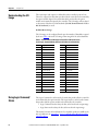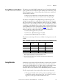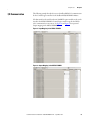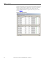
1
User Manual
PowerFlex 20-750-PBUS
Profibus DPV1 Option Module
FRN 1.xxx
Important User Information
Solid-state equipment has operational characteristics differing from those of electromechanical equipment. Safety
Guidelines for the Application, Installation and Maintenance of Solid State Controls (publication SGI-1.1 available from your
local Rockwell Automation sales office or online at http://www.rockwellautomation.com/literature/) describes some
important differences between solid-state equipment and hard-wired electromechanical devices. Because of this difference,
and also because of the wide variety of uses for solid-state equipment, all persons responsible for applying this equipment
must satisfy themselves that each intended application of this equipment is acceptable.
In no event will Rockwell Automation, Inc. be responsible or liable for indirect or consequential damages resulting from
the use or application of this equipment.
The examples and diagrams in this manual are included solely for illustrative purposes. Because of the many variables and
requirements associated with any particular installation, Rockwell Automation, Inc. cannot assume responsibility or
liability for actual use based on the examples and diagrams.
No patent liability is assumed by Rockwell Automation, Inc. with respect to use of information, circuits, equipment, or
software described in this manual.
Reproduction of the contents of this manual, in whole or in part, without written permission of Rockwell Automation,
Inc., is prohibited.
Throughout this manual, when necessary, we use notes to make you aware of safety considerations.
WARNING: Identifies information about practices or circumstances that can cause an explosion in a hazardous
environment, which may lead to personal injury or death, property damage, or economic loss.
ATTENTION: Identifies information about practices or circumstances that can lead to personal injury or death,
property damage, or economic loss. Attentions help you identify a hazard, avoid a hazard, and recognize the
consequence.
SHOCK HAZARD: Labels may be on or inside the equipment, for example, a drive or motor, to alert people that
dangerous voltage may be present.
BURN HAZARD: Labels may be on or inside the equipment, for example, a drive or motor, to alert people that
surfaces may reach dangerous temperatures.
IMPORTANT
Identifies information that is critical for successful application and understanding of the product.
Allen-Bradley, Rockwell Software, Rockwell Automation, and TechConnect are trademarks of Rockwell Automation, Inc.
Trademarks not belonging to Rockwell Automation are property of their respective companies.
Summary of Changes
This manual contains new and updated information.
New and Updated
Information
This table contains the changes made to this revision.
Topic
Page
Added information about the Connected Components Workbench software tool.
Throughout
manual
Added Important statement about the larger T15 Torx head mounting screw to step 3 in
the ‘Quick Start’ table.
17
Updated option module mounting information in the section ‘Connecting Option
Module to the Drive’. The larger T15 Torx head screw, if present, on a module in the
adjacent port the left of the 20-750-PBUS module must be replaced with a smaller,
spare T8 Torx head screw to prevent possible electrical contact.
22
Rockwell Automation Publication 750COM-UM004B-EN-P - September 2012
3
Summary of Changes
Notes:
4
Rockwell Automation Publication 750COM-UM004B-EN-P - September 2012
Table of Contents
Preface
Conventions Used in This Manual . . . . . . . . . . . . . . . . . . . . . . . . . . . . . . . . . 9
Rockwell Automation Support . . . . . . . . . . . . . . . . . . . . . . . . . . . . . . . . . . . . . 9
Additional Resources . . . . . . . . . . . . . . . . . . . . . . . . . . . . . . . . . . . . . . . . . . . . . 10
Chapter 1
Getting Started
Components. . . . . . . . . . . . . . . . . . . . . . . . . . . . . . . . . . . . . . . . . . . . . . . . . . . . .
Features . . . . . . . . . . . . . . . . . . . . . . . . . . . . . . . . . . . . . . . . . . . . . . . . . . . . . . . . .
Understanding Parameter Types. . . . . . . . . . . . . . . . . . . . . . . . . . . . . . . . . . .
Compatible Products . . . . . . . . . . . . . . . . . . . . . . . . . . . . . . . . . . . . . . . . . . . . .
Required Equipment . . . . . . . . . . . . . . . . . . . . . . . . . . . . . . . . . . . . . . . . . . . . .
Safety Precautions . . . . . . . . . . . . . . . . . . . . . . . . . . . . . . . . . . . . . . . . . . . . . . . .
Quick Start . . . . . . . . . . . . . . . . . . . . . . . . . . . . . . . . . . . . . . . . . . . . . . . . . . . . . .
11
12
13
13
13
16
17
Chapter 2
Installing the Option Module
Preparing for an Installation. . . . . . . . . . . . . . . . . . . . . . . . . . . . . . . . . . . . . . .
Setting the Endianness and Node Address Switches . . . . . . . . . . . . . . . . .
Connecting the Option Module to the Drive . . . . . . . . . . . . . . . . . . . . . . .
Connecting the Option Module to the Network . . . . . . . . . . . . . . . . . . . .
Network Termination . . . . . . . . . . . . . . . . . . . . . . . . . . . . . . . . . . . . . . . . . . . .
Applying Power . . . . . . . . . . . . . . . . . . . . . . . . . . . . . . . . . . . . . . . . . . . . . . . . . .
19
20
22
23
24
25
Chapter 3
Configuring the Option Module
Configuration Tools. . . . . . . . . . . . . . . . . . . . . . . . . . . . . . . . . . . . . . . . . . . . . .
Using the PowerFlex 20-HIM-A6 or 20-HIM-C6S HIM to Access
Parameters . . . . . . . . . . . . . . . . . . . . . . . . . . . . . . . . . . . . . . . . . . . . . . . . .
Setting the Node Address . . . . . . . . . . . . . . . . . . . . . . . . . . . . . . . . . . . . . . . . .
Setting a Master-Slave Hierarchy (Optional) . . . . . . . . . . . . . . . . . . . . . . .
Setting a Fault Action . . . . . . . . . . . . . . . . . . . . . . . . . . . . . . . . . . . . . . . . . . . .
Resetting the Option Module . . . . . . . . . . . . . . . . . . . . . . . . . . . . . . . . . . . . .
Restoring Option Module Parameters to Factory Defaults . . . . . . . . . . .
Viewing the Option Module Status Using Parameters . . . . . . . . . . . . . . .
Updating the Option Module Firmware . . . . . . . . . . . . . . . . . . . . . . . . . . .
29
30
30
30
33
34
35
36
37
Chapter 4
Configuring the Profibus Master Example Network . . . . . . . . . . . . . . . . . . . . . . . . . . . . . . . . . . . . . . . . . . . . . . . . 39
Configuring the MVI56-PDPMV1 Profibus DPV1 Master . . . . . . . . . . 40
Installing GSD Files . . . . . . . . . . . . . . . . . . . . . . . . . . . . . . . . . . . . . . . . . . . . . . 43
Configuring the Option Module as a Slave . . . . . . . . . . . . . . . . . . . . . . . . . 45
Rockwell Automation Publication 750COM-UM004B-EN-P - September 2012
5
Table of Contents
Chapter 5
Using the I/O
About I/O Messaging. . . . . . . . . . . . . . . . . . . . . . . . . . . . . . . . . . . . . . . . . . . . .
Understanding the I/O Image . . . . . . . . . . . . . . . . . . . . . . . . . . . . . . . . . . . . .
Using Logic Command/Status . . . . . . . . . . . . . . . . . . . . . . . . . . . . . . . . . . . .
Using Reference/Feedback . . . . . . . . . . . . . . . . . . . . . . . . . . . . . . . . . . . . . . . .
Using Datalinks . . . . . . . . . . . . . . . . . . . . . . . . . . . . . . . . . . . . . . . . . . . . . . . . . .
I/O Communication . . . . . . . . . . . . . . . . . . . . . . . . . . . . . . . . . . . . . . . . . . . . .
51
52
52
53
53
55
Chapter 6
Acyclic Messaging
About Acyclic Messaging. . . . . . . . . . . . . . . . . . . . . . . . . . . . . . . . . . . . . . . . . . 57
Acyclic Messaging for DPV1 Class 1 . . . . . . . . . . . . . . . . . . . . . . . . . . . . . . . 60
Example Messaging . . . . . . . . . . . . . . . . . . . . . . . . . . . . . . . . . . . . . . . . . . . . . . . 60
Chapter 7
Troubleshooting
Understanding the Status Indicators . . . . . . . . . . . . . . . . . . . . . . . . . . . . . . .
PORT Status Indicator . . . . . . . . . . . . . . . . . . . . . . . . . . . . . . . . . . . . . . . . . . .
MOD Status Indicator. . . . . . . . . . . . . . . . . . . . . . . . . . . . . . . . . . . . . . . . . . . .
NET A Status Indicator. . . . . . . . . . . . . . . . . . . . . . . . . . . . . . . . . . . . . . . . . . .
Viewing Option Module Diagnostic Items . . . . . . . . . . . . . . . . . . . . . . . . .
Viewing and Clearing Events . . . . . . . . . . . . . . . . . . . . . . . . . . . . . . . . . . . . . .
65
66
67
67
68
70
Appendix A
Specifications
Communications. . . . . . . . . . . . . . . . . . . . . . . . . . . . . . . . . . . . . . . . . . . . . . . . .
Electrical . . . . . . . . . . . . . . . . . . . . . . . . . . . . . . . . . . . . . . . . . . . . . . . . . . . . . . . .
Mechanical . . . . . . . . . . . . . . . . . . . . . . . . . . . . . . . . . . . . . . . . . . . . . . . . . . . . . .
Environmental . . . . . . . . . . . . . . . . . . . . . . . . . . . . . . . . . . . . . . . . . . . . . . . . . . .
Regulatory Compliance . . . . . . . . . . . . . . . . . . . . . . . . . . . . . . . . . . . . . . . . . . .
73
73
73
74
74
Appendix B
Option Module Parameters
Parameter Types . . . . . . . . . . . . . . . . . . . . . . . . . . . . . . . . . . . . . . . . . . . . . . . . .
About Parameter Numbers. . . . . . . . . . . . . . . . . . . . . . . . . . . . . . . . . . . . . . . .
How Parameters Are Organized . . . . . . . . . . . . . . . . . . . . . . . . . . . . . . . . . . .
Device Parameters . . . . . . . . . . . . . . . . . . . . . . . . . . . . . . . . . . . . . . . . . . . . . . . .
Host Parameters . . . . . . . . . . . . . . . . . . . . . . . . . . . . . . . . . . . . . . . . . . . . . . . . .
75
76
76
76
78
Appendix C
Logic Command/Status Words:
PowerFlex 750-Series Drives
Logic Command Word . . . . . . . . . . . . . . . . . . . . . . . . . . . . . . . . . . . . . . . . . . . 83
Logic Status Word . . . . . . . . . . . . . . . . . . . . . . . . . . . . . . . . . . . . . . . . . . . . . . . 84
Appendix D
History of Changes
6
750COM-UM004A-EN-P, August 20112 . . . . . . . . . . . . . . . . . . . . . . . . . 85
Rockwell Automation Publication 750COM-UM004B-EN-P - September 2012
Table of Contents
Glossary
Index
Rockwell Automation Publication 750COM-UM004B-EN-P - September 2012
7
Table of Contents
Notes:
8
Rockwell Automation Publication 750COM-UM004B-EN-P - September 2012
Preface
This manual provides information about the 20-750-PBUS Profibus DPV1
option module for network communications option and how to use the module
with PowerFlex® 750-Series drives.
Conventions Used in This
Manual
The following conventions are used throughout this manual:
• Parameter names are shown in the format Device Parameter xx - [*] or
Host Parameter xx - [*]. The xx represents the parameter number. The *
represents the parameter name—for example Device Parameter 01 - [DPI
Port].
• The firmware revision number (FRN) is displayed as FRN X.xxx, where
‘X’ is the major revision number and ‘xxx’ is the minor revision number.
• For the screen displays in this manual, the following software was used:
– Prosoft Configuration Builder software, version 2.2.2.3
– DriveExplorer™ Full software, version 6.02.99
Different versions of the software may differ in appearance and
procedures.
Rockwell Automation
Support
Rockwell Automation offers support services worldwide, with over 75 sales and
support offices, over 500 authorized distributors, and over 250 authorized
systems integrators located through the United States alone. In addition,
Rockwell Automation representatives are in every major country in the world.
Local Product Support
Contact your local Rockwell Automation representative for the following:
• Sales and order support
• Product technical training
• Warranty support
• Support service agreements
Technical Product Assistance
For technical assistance, please review the information in Chapter 7,
Troubleshooting, first. If you still have problems, then access the Allen-Bradley
Technical Support website at http://www.ab.com/support/abdrives or contact
Rockwell Automation.
Rockwell Automation Publication 750COM-UM004B-EN-P - September 2012
9
Preface
Additional Resources
These documents contain additional information concerning related products
from Rockwell Automation and others.
Resource
Description
Network Communication Option Module Installation Instructions, publication
750COM-IN002
Information on the installation of PowerFlex 750-Series Network
Communication Modules.
Profibus Installation Guideline at http://www.profibus.com/
Information on the planning, installation, and techniques used to
implement a Profibus network.
Prosoft Configuration Builder at http://www.prosoft-technology.com/prosoft/
products/prosoft_software/pcb
Information on using the Prosoft Configuration Builder software
tool, version 2.2.2.3.
Profibus Master (Prosoft MVI56-PDPMV1) at http://www.prosoft-technology.com/
content/view/full/8109
Information on using the Prosoft MVI56-PDPMV1 Profibus
master.
Profibus Standard at http://www.profibus.com/
Information on Profibus standards and specifications.
Connected Components Workbench website http://www.ab.rockwellautomation.com/ Information on the Connected Components Workbench™
Drives/Software/9328-ConnectedComponentsWorkbench
software tool—and includes link for free software download.
DriveExplorer website http://www.ab.com/drives/driveexplorer, and online help
Information on using the DriveExplorer software tool.
DriveExecutive website http://www.ab.com/drives/drivetools, and online help
Information on using the DriveExecutive™ software tool.
PowerFlex 750-Series Drive Installation Instructions, publication 750-IN001
Information on the installation, programming, and technical data
of PowerFlex 750-Series Drives.
PowerFlex 750-Series Drive Programming Manual, publication 750-PM001
PowerFlex 750-Series Drive Technical Data, publication 750-TD001
Power-Flex 20-HIM-A6/-C6S (Human Interface Module) User Manual, publication
20HIM-UM001
Information on the installation and use of PowerFlex 20-HIM-A6
or 20-HIM-C6S HIMs.
Documentation can be obtained online at http://
www.rockwellautomation.com/literature. To order paper copies of technical
documentation, contact your local Rockwell Automation distributor or sales
representative.
To find your local Rockwell Automation distributor or sales representative, visit
http://www.rockwellautomation.com/locations.
For information such as firmware updates or answers to drive-related questions,
go to the Drives Service & Support web site at http://www.ab.com/support/
abdrives and click on the Downloads or Knowledgebase link.
10
Rockwell Automation Publication 750COM-UM004B-EN-P - September 2012
Chapter
1
Getting Started
The 20-750-PBUS option module is intended for installation into a PowerFlex
750-Series drive and is used for network communication.
Topic
Page
Components
11
Features
12
Understanding Parameter Types
13
Compatible Products
13
Required Equipment
13
Safety Precautions
16
Quick Start
17
Components
➊
➋
➌
Item
Part
Description
➊
Status Indicators
Three status indicators that indicate the
status of the option module and network
communication. See Chapter 7,
Troubleshooting.
➋
Node Address Switches
(Switches 1…7)
Sets the node address of the option
module. See Setting the Endianness and
Node Address Switches on page 20.
Endianness Selection
Switch (Switch 8)
Sets the endianness of data transmitted
over network.
➌
Selection Jumper
Selects between Profibus or Profidrive
operation mode.
Important: This feature is not supported
in this version, so changing the jumper
position will not have any effect. The
Profibus operating mode is selected with
either position.
➍
Profibus DB9 Female
Connector
Profibus connector for the Profibus
network cable.
8
7
6
5
4
3
2
1
➍
Rockwell Automation Publication 750COM-UM004B-EN-P - September 2012
11
Chapter 1
Features
Getting Started
The features of the option module include the following:
• Captive screws to secure and ground the option module to the drive.
• Switches to set a node address before applying power to the drive—or you
can disable the switches and use an option module parameter to configure
the node address.
• Compatibility with various configuration tools to configure the option
module and host drive, including the following tools:
– PowerFlex 20-HIM-A6 or 20-HIM-C6S HIM (Human Interface
Module) on the drive, if available
– Connected Components Workbench software, version 1.02 or later
– DriveExplorer software, version 6.01 or later
– DriveExecutive software, version 5.01 or later
– DriveObserver software, version 5.01 or later
– ControlFlash software, version 7.00 or later
– Third party Profibus configuration software, such as Prosoft
Configuration Builder
• Status indicators that report the status of the option module and network
communication. They are visible when the drive cover is open or removed.
• Parameter-configured 32-bit Datalinks in the I/O to meet application
requirements (16 Datalinks to write data from the network to the drive,
and 16 Datalinks to read data to the network from the drive).
• Acyclic Messaging support.
• Master-Slave hierarchy that can be set up so that the option module and
PowerFlex 750-Series drive transmit data to and from a master on the
network.
• User-defined fault actions to determine how the option module and
connected drive respond to the following:
– I/O messaging communication disruptions (Comm Flt Action)
– Controllers in Idle mode (Idle Flt Action)
– Acyclic messaging
12
Rockwell Automation Publication 750COM-UM004B-EN-P - September 2012
Getting Started
Understanding Parameter
Types
Chapter 1
The option module has two types of parameters:
• Device parameters are used to configure the option module to operate on
the network.
• Host parameters are used to configure the option module Datalink transfer
and various fault actions with the drive.
You can view option module Device parameters and Host parameters with any of
the following drive configuration tools:
• PowerFlex 20-HIM-A6 or 20-HIM-C6S HIM—use the
or
key to scroll to the drive port in which the module resides, press the
(Folders) key, and use the
or
key to scroll to the DEV
PARAM or HOST PARAM folder.
• Connected Components Workbench software—click the tab for the
option module at the bottom of the window, click the Parameters icon in
the tool bar, and click the Device or Host Parameters tab.
• DriveExplorer software—find the option module in the treeview and open
its Parameters folder.
• DriveExecutive software—find the option module in the treeview, expand
the module in the tree, and open its Parameters folder.
Compatible Products
At the time of publication, the option module is compatible with the following:
• PowerFlex 753 drives (all firmware revisions)
• PowerFlex 755 drives (all firmware revisions)
Required Equipment
Some of the equipment that is required for use with the option module is shipped
with the module, but some you must provide yourself.
Equipment Shipped with the Option Module
When you unpack the option module, verify that the package includes the
following:
❑ One 20-750-PBUS Profibus Option Module
❑ One Network Communication Option Card Installation Instructions,
publication 750COM-IN002
Rockwell Automation Publication 750COM-UM004B-EN-P - September 2012
13
Chapter 1
Getting Started
User-Supplied Equipment
To install and configure the option module, you must supply the following:
❑ A small screwdriver
❑ Profibus cable; only use cable that conforms to Profibus cable standards
(Belden #3079A Profibus cable or equivalent is recommended)
❑ One 9-pin, male D-Sub Profibus connector
Profibus connectors are available from a variety of sources and in various
sizes. As such, there may be mechanical limitations that prohibit the use of
some connectors. Phoenix SUBCON-PLUS-PROFIB/AX/SC (Part #
2744380), Siemens 6GK1500-0FC00, or Brad BM5G60PP4Mxxx are
recommended for use with PowerFlex 750 drives.
❑ Configuration tool, such as the following:
– PowerFlex 20-HIM-A6 or 20-HIM-C6S HIM
– Connected Components Workbench software, version 1.02 or later
Connected Components Workbench is the recommended stand-alone
software tool for use with PowerFlex drives. You can obtain a free copy
by:
• Internet download at http://www.ab.rockwellautomation.com/
Drives/Software/9328-ConnectedComponentsWorkbench
• Requesting a DVD at http://www.ab.com/onecontact/
controllers/micro800/
Your local distributor may also have copies of the DVD available.
Connected Components Workbench software cannot be used to
configure SCANport-based drives or Bulletin 160 drives.
– DriveExplorer software, version 6.01 or later
This software tool has been discontinued and is now available as
freeware at http://www.ab.com/support/abdrives/webupdate/
software.html. There are no plans to provide future updates to this tool
and the download is being provided ‘as-is’ for users that lost their
DriveExplorer CD, or need to configure legacy products not supported
by Connected Components Workbench software.
14
Rockwell Automation Publication 750COM-UM004B-EN-P - September 2012
Getting Started
Chapter 1
– DriveExecutive software, version 5.01 or later
A Lite version of DriveExecutive software ships with RSLogix 5000,
RSNetworx MD, FactoryTalk AssetCentre, and IntelliCENTER
software. All other versions are purchasable items:
• 9303-4DTE01ENE Drive Executive software
• 9303-4DTS01ENE DriveTools SP Suite (includes
DriveExecutive and DriveObserver software)
• 9303-4DTE2S01ENE DriveExecutive software upgrade to
DriveTools SP Suite (adds DriveObserver software)
DriveExecutive software updates (patches, and so forth) can be obtained
at http://www.ab.com/support/abdrives/webupdate/software.html. It
is highly recommended that you periodically check for and install the
latest update.
❑ Controller configuration software RSLogix 5000
❑ A computer connection to the Profibus DPV1 network
Rockwell Automation Publication 750COM-UM004B-EN-P - September 2012
15
Chapter 1
Getting Started
Safety Precautions
Please read the following safety precautions carefully.
ATTENTION: Risk of injury or death exists. The PowerFlex drive may
contain high voltages that can cause injury or death. Remove all power
from the PowerFlex drive, and then verify power has been discharged
before installing or removing the option module.
ATTENTION: Risk of injury or equipment damage exists. Only personnel
familiar with drive and power products and the associated machinery
should plan or implement the installation, startup, configuration, and
subsequent maintenance of the drive using the option module. Failure to
comply may result in injury and/or equipment damage.
ATTENTION: Risk of equipment damage exists. The option module
contains electrostatic discharge (ESD) sensitive parts that can be damaged
if you do not follow ESD control procedures. Static control precautions are
required when handling the option module. If you are unfamiliar with static
control procedures, see Guarding Against Electrostatic Damage,
publication 8000-4.5.2.
ATTENTION: Risk of injury or equipment damage exists. If the option
module is transmitting control I/O to the drive, the drive may fault when
you reset the option module. Determine how your drive will respond before
resetting the module.
ATTENTION: Risk of injury or equipment damage exists. Host
Parameters 33 - [Comm Flt Action], and 34 - [Idle Flt Action] let you
determine the action of the option module and connected drive if I/O
communication is disrupted, the controller is idle, or Acyclic messaging for
drive control is disrupted. By default, these parameters fault the drive. You
can set these parameters so that the drive continues to run, however,
precautions should be taken to verify that the settings of these parameters
do not create a risk of injury or equipment damage. When commissioning
the drive, verify that your system responds correctly to various situations
(for example, a disconnected cable or a controller in idle state).
ATTENTION: Risk of injury or equipment damage exists. When a system is
configured for the first time, there may be unintended or incorrect machine
motion. Disconnect the motor from the machine or process during initial
system testing.
ATTENTION: Risk of injury or equipment damage exists. The examples in
this publication are intended solely for purposes of example. There are
many variables and requirements with any application. Rockwell
Automation does not assume responsibility or liability (to include
intellectual property liability) for actual use of the examples shown in this
publication.
16
Rockwell Automation Publication 750COM-UM004B-EN-P - September 2012
Getting Started
Quick Start
Chapter 1
This section is provided to help experienced users quickly start using the Option
Module. If you are unsure how to complete a step, refer to the referenced chapter.
Step Action
See
1
Review the safety precautions for the option module.
Throughout this manual
2
Verify that the PowerFlex drive is properly installed.
PowerFlex 750-Series AC Drive
Installation Instructions,
publication 750-IN001
3
Install the option module.
Network Communication Option
Card Installation Instructions,
publication 750COM-IN002 and
Chapter 2,
Installing the Option Module
a. Verify that the PowerFlex drive is not powered.
b. Insert the option module in drive Port 4, 5 or 6. Use
the captive screws to secure and ground the option
module to the drive.
c. Connect the option module to the network by using
a Profibus cable.
Important: When another module (I/O, encoder,
communication, and so forth) resides in the adjacent port
to the left of the 20-750-PBUS option module—and the
lower mounting screw of that module is a larger T15 Torx
head screw, perform additional steps 2a through 2d on
page 22.
4
Apply power to the option module.
a. The option module receives power from the drive.
Verify that the option module is installed correctly
and then apply power to the drive. The status
indicators should be green. If they flash red, there is
a problem. See Chapter 7, Troubleshooting.
Chapter 2,
Installing the Option Module
b. Configure and verify key drive parameters.
5
Configure the option module for your application.
Set option module parameters for the following functions
as required by your application:
•
•
•
•
6
Chapter 3,
Configuring the Option Module
Node address
I/O configuration
Master-Slave hierarchy
Fault actions
Configure the Profibus Master to communicate with the
option module.
Chapter 4,
Configuring the Profibus Master
Use controller configuration tools such as Prosoft
Configuration Builder software for Profibus and RSLogix
5000 software to configure the master on the Profibus
network to recognize the option module and drive.
7
Configure the I/O.
Use a controller configuration tool such as RSLogix 5000
software that enables you to control the option module
and connected drive using I/O.
Rockwell Automation Publication 750COM-UM004B-EN-P - September 2012
Chapter 5,
Using the I/O
17
Chapter 1
Getting Started
Notes:
18
Rockwell Automation Publication 750COM-UM004B-EN-P - September 2012
Chapter
2
Installing the Option Module
This chapter provides instructions for installing the option module in a
PowerFlex 750-Series drive.
Preparing for an
Installation
Topic
Page
Preparing for an Installation
19
Setting the Endianness and Node Address Switches
20
Connecting the Option Module to the Drive
22
Connecting the Option Module to the Network
23
Network Termination
24
Applying Power
25
Before installing the option module, do the following:
• Read the Profibus Installation Guideline for details on Profibus networks.
• Verify that you have all required equipment. See Required Equipment on
page 13.
ATTENTION: Risk of equipment damage exists. The option module
contains electrostatic discharge (ESD) sensitive parts that can be damaged
if you do not follow ESD control procedures. Static control precautions are
required when handling the option module. If you are unfamiliar with static
control procedures, see Guarding Against Electrostatic Damage,
publication 8000-4.5.2.
Rockwell Automation Publication 750COM-UM004B-EN-P - September 2012
19
Chapter 2
Installing the Option Module
Setting the Endianness and
Node Address Switches
Set the Endianness of the option module with Byte Swap switch 8 (see Figure 1).
The Byte Swap switch can be set to either open ‘0’ (Little Endian) or closed ‘1’
(Big Endian) data formats for the cyclic data exchanged on the network. The
cyclic data consists of the following items:
• CTRL: Logic Command Word (4 bytes)
• REF: Speed Reference (4 bytes)
• STAT: Logic Status Word (4 bytes)
• FEEDBACK: Speed Feedback (4 bytes)
• 0 to 16 Datalinks (4 bytes each)
Depending on the setting of the Byte Swap switch 8, the 4 bytes for each of the
above data items are swapped.
Figure 1 - Setting Option Module Node Address Switches
Byte Swap
Switch 8
8
7
6
8
7
6
5
4
3
2
1
Node Addr
Switches
1…7
5
4
3
2
1
IMPORTANT
Each node on the Profibus network must have a unique address. Set the
node address before power is applied because the option module
detects the node address during initialization (Power On Reset). To
change a node address, you must set the new value and then remove
and reapply power to (or reset) the option module.
Set the Node Address by setting Node Address switches 1 through 7 to their
binary equivalent, where '0' and '1' indicate switch positions 'Open' and 'Closed'
respectively. Table 1 lists node addresses and the corresponding Node Address
switch settings required to set that respective address.
20
Rockwell Automation Publication 750COM-UM004B-EN-P - September 2012
Installing the Option Module
Chapter 2
Node Address Switch
1
Node
Address
7
6
5
4
3
2
1
0
0
14
0
0
0
1
1
1
0
0
1
15
0
0
0
1
1
1
1
0
1
0
16
0
0
1
0
0
0
0
0
0
1
1
17
0
0
1
0
0
0
1
0
0
1
0
0
18
0
0
1
0
0
1
0
0
0
1
0
1
19
0
0
1
0
0
1
1
0
0
0
1
1
0
20
0
0
1
0
1
0
0
0
0
0
0
1
1
1
…
Table 1 - Node Address Switch Settings
Node Address Switch
08
0
0
0
1
0
0
0
120
1
1
1
1
0
0
0
09
0
0
0
1
0
0
1
121
1
1
1
1
0
0
1
10
0
0
0
1
0
1
0
122
1
1
1
1
0
1
0
11
0
0
0
1
0
1
1
123
1
1
1
1
0
1
1
12
0
0
0
1
1
0
0
124
1
1
1
1
1
0
0
13
0
0
0
1
1
0
1
125
1
1
1
1
1
0
1
Node
Address
7
6
5
4
3
2
00
0
0
0
0
0
01
0
0
0
0
0
02
0
0
0
0
03
0
0
0
04
0
0
05
0
0
06
0
07
Descriptions of node address values are as follows.
Node Address Value
Description
00
If the Node Address value is set to ‘00’, the option module uses Device
Parameter 05 - [Net Addr Cfg] to set the Node Address. See Setting the
Node Address on page 30.
01…125
Node address used by the option module.
126
The default address setting.
The switch settings can be verified by viewing Device Parameter 06 - [Net Addr
Act], a read-only parameter, with any of the following drive configuration tools:
• PowerFlex 20-HIM-A6 or 20-HIM-C6S HIM
• Connected Components Workbench software, version 1.02 or later
• DriveExplorer software, version 6.01 or later
• DriveExecutive software, version 5.01 or later
Rockwell Automation Publication 750COM-UM004B-EN-P - September 2012
21
Chapter 2
Installing the Option Module
Connecting the Option
Module to the Drive
IMPORTANT
Remove power from the drive before installing the option module in the
drive control pod.
1. Insert the option module into Port 4, 5, or 6 and tighten the module
mounting screws into the pod mounting bracket. To properly ground the
module to the drive, torque both mounting screws to 0.45…0.67 N•m
(4.0…6.0 lb•in).
2. When another module (I/O, encoder, communication, and so forth)
resides in the adjacent port to the left of the 20-750-PBUS option
module—and the lower mounting screw of that module is a larger T15
Torx head screw, perform addition steps 2a through 2d. If the port is
empty or the adjacent module already uses the smaller T8 Torx head
mounting screws, save this spare screw for future use.
The option module is shipped with a small bag containing a spare T8 Torx
head mounting screw and an adhesive-backed polycarbonate insulator
strip. The larger T15 Torx head mounting screw on the adjacent left
module may electrically contact the metal Profibus cable connector when
attached to the Profibus module. The polycarbonate insulator strip is
provided to prevent electrical contact between the smaller T8 Torx head
mounting screw and the Profibus cable metal connector when attached to
the Profibus module. Either of these possible electrical contact situations
may cause faulty operation. To prevent this, perform the following steps.
a. Remove the adjacent module’s lower mounting screw, the T15 Torx
head screw closest to the bottom of the pod mounting bracket.
TIP
To remove the captive T15 Torx head screw, the module must be
removed to back the screw out of the mounting clip.
b. Replace the larger T15 Torx head screw with the smaller, spare T8 Torx
head mounting screw.
c. Tighten the mounting screw to the pod mounting bracket to properly
ground the adjacent module to the drive. Torque the screw to
0.45…0.67 N•m (4.0…6.0 lb•in).
d. Attach the adhesive-backed polycarbonate strip to the metal Profibus
cable connector in a location that prevents electrical contact between
the connector and the adjacent module’s lower mounting screw when
the connector is attached to the Profibus module.
22
Rockwell Automation Publication 750COM-UM004B-EN-P - September 2012
Installing the Option Module
Connecting the Option
Module to the Network
Chapter 2
ATTENTION: Risk of injury or death exists. The PowerFlex drive may
contain high voltages that can cause injury or death. Remove power from
the drive, and then verify power has been discharged before connecting the
option module to the network.
1. Remove power from the drive.
2. Remove the drive cover and lift up the drive HIM bezel to its open
position to access the drive control pod.
3. Use static control precautions.
4. Route the Profibus cable through the bottom of the PowerFlex drive.
5. Connect a Profibus connector to the cable.
Profibus connectors are available from a variety of sources and in various
sizes. As such, there may be mechanical limitations that prohibit the use of
some connectors. Phoenix SUBCON-PLUS-PROFIB/AX/SC (Part #
2744380), Siemens 6GK1500-0FC00, or Brad BM5G60PP4Mxxx are
recommended for use with PowerFlex 750-Series drives.
Figure 2 - Profibus Connector
6. Connect the Profibus cable to the option module and secure it with the
two screws on the connector.
IMPORTANT
Profibus communication may not operate correctly if the
cable shield does not make full contact with the
connector housing.
Figure 3 - Network Wiring Diagram
B
A
B
A
B
A
B
A
Rockwell Automation Publication 750COM-UM004B-EN-P - September 2012
B
A
B
A
23
Chapter 2
Installing the Option Module
Terminal
Signal
Function
Housing
Shield
Bus cable shield (outer screen that surrounds A and B
conductors)
1
Not connected
—
2
Not connected
—
3
B-LINE
Positive RxD/TxD, according to RS485 specification
4
RTS
Request to send
5
GND BUS
Network Zero Volt Reference (isolated from drive side)
6
+5V BUS
+5V output to network (isolated from drive side)
7
Not connected
—
8
A-LINE
Negative RxD/TxD according to RS485 specification
9
Not connected
—
7. Ground the shield to reduce electrostatic pickup. However, shielding is
only effective when the shield is properly connected to ground. See the
Profibus Installation Guideline for instructions to correctly ground the
shield.
Figure 4 - Wiring Example
PowerFlex 750-Series Drives
(with 20-750-PBUS Option Modules)
ControlLogix
Controller
Profibus Network
8. Connect the other end of the Profibus cable that is routed through the
bottom of the drive to the Profibus network.
Network Termination
The first and last node on a Profibus DP Network segment should be terminated.
Rockwell Automation recommends that the user select one of the
aforementioned Profibus connectors with built-in termination.
24
Rockwell Automation Publication 750COM-UM004B-EN-P - September 2012
Installing the Option Module
Applying Power
Chapter 2
ATTENTION: Risk of equipment damage, injury, or death exists.
Unpredictable operation may occur if you fail to verify that parameter
settings are compatible with your application. Verify that settings are
compatible with your application before applying power to the drive.
Apply power to the drive. The option module receives its power from the drive.
When you apply power to the option module for the first time, its topmost
PORT status indicator should be steady green or flashing green after
initialization. If it is red, there is a problem. See Chapter 7, Troubleshooting.
Start-Up Status Indications
The drive STS (status) indicator can be viewed on front of the drive after power
has been applied. The option module status indicators can be viewed with the
drive cover open or removed (Figure 5).
Figure 5 - Drive and Option Module Status Indicators
➊
➋
➌
➍
See Table 2 for
possible start-up
status indications
Drive Control Pod
Rockwell Automation Publication 750COM-UM004B-EN-P - September 2012
25
Chapter 2
Installing the Option Module
Table 2 - Drive and Option Module Start-Up Status Indications
Item Name
Color
State
Description
Drive STS Indicator
➊
STS
Green
(Status)
Yellow
Red
Flashing
Drive ready but not running, and no faults are present.
Steady
Drive running, no faults are present.
Flashing
When running, a type 2 (non-configurable) alarm condition exists – drive
continues to run. When stopped, a start inhibit condition exists and the
drive cannot be started (see drive parameter 933 - [Start Inhibits]).
Steady
A type 1 (user configurable) alarm condition exists, but the drive
continues to run.
Flashing
A major fault has occurred. Drive will stop. Drive cannot be started until
fault condition is cleared.
Steady
A non-resettable fault has occurred.
Red/Yellow
Flashing
Alternately
A minor fault has occurred. Use drive parameter 950 - [Minor Flt Config]
to enable. If not enabled, acts like a major fault. When running, the drive
continues to run. System is brought to a stop under system control. The
fault must be cleared to continue.
Yellow/Green
Flashing
Alternately
When running, a type 1 alarm exists.
Green/Red
Flashing
Alternately
Drive is updating.
Option Module Status Indicators
➋
PORT
—
Red
MOD
Flashing
The option module is not receiving any communication from drive.
The option module detected a duplicate or invalid port ID.
Flashing
The option module is establishing communication with drive.
Steady
The option module is properly connected and communicating with drive.
Orange
Steady
The drive to which option module is connected is not an Allen-Bradley
brand.
—
Off
The option module is not powered or connected properly to the drive.
Red
Flashing
The option module has failed the firmware test or firmware update is in
progress.
Steady
The option module has failed the hardware test.
Green
➍
NET A
The option module is not powered or connected properly to the drive.
Steady
Green
➌
Off
Flashing
The option module is operational but is not transferring I/O data.
Steady
The option module is operational and is transferring I/O data.
—
Off
The option module cannot establish network communication or has
experienced a Communication Timeout.
Red
Flashing
The option module has detected a Network Configuration Error.
Steady
The option module has experienced an internal network controller error
(Profibus ASIC Self-Test failure).
Steady
The option module is properly connected and communicating over the
Profibus network.
Green
After verifying correct operation, swing down the drive HIM bezel to its closed
position and install the drive cover. For more details on status indicator
operation, see page 66 and page 67.
26
Rockwell Automation Publication 750COM-UM004B-EN-P - September 2012
Installing the Option Module
Chapter 2
Configuring and Verifying Key Drive Parameters
The PowerFlex 750-Series drive can be separately configured for the control and
Reference functions in various combinations. For example, you could set the drive
to receive control commands from a peripheral or terminal block, with the
Reference coming from the network. You could also set the drive to receive its
control from the network with the Reference coming from another peripheral or
terminal block. Or you could set the drive to receive both its control and
Reference from the network.
The following steps in this section assume that the drive will receive the Logic
Command and Reference from the network.
1. Verify that drive parameter 301 - [Access Level] is set to ‘1’ (Advanced) or
‘2’ (Expert) to access the required parameters in this procedure.
2. Use drive Parameter 545 - [Speed Ref A Sel] to set the drive speed
Reference source:
a. Set the Port field to ‘0’ as shown below.
b. Set the Parameter field to point to the port (slot) in which the option
module is installed (for example, Port 4 Reference).
The number ‘874’ in the Parameter field of the example dialog box
above is the parameter in the drive that points to the port.
3. Verify that drive Parameter 930 - [Speed Ref Source] is reporting that the
source of the Reference to the drive (Port 0) is the port in which the option
module is installed (for example, Port 4 Reference).
This ensures that any Reference commanded from the network can be
monitored by using drive Parameter 002 - [Commanded SpdRef ]. If a
Rockwell Automation Publication 750COM-UM004B-EN-P - September 2012
27
Chapter 2
Installing the Option Module
problem occurs, this verification step provides the diagnostic capability to
determine whether the drive/option module or the network is the cause.
4. If hard-wired discrete digital inputs are not used to control the drive, verify
that all unused digital input drive parameters are set to ‘0’ (Not Used).
28
Rockwell Automation Publication 750COM-UM004B-EN-P - September 2012
Chapter
3
Configuring the Option Module
This chapter provides instructions and information for setting the parameters to
configure the option module.
Topic
Page
Configuration Tools
29
Using the PowerFlex 20-HIM-A6 or 20-HIM-C6S HIM to Access Parameters
30
Setting the Node Address
30
Setting a Master-Slave Hierarchy (Optional)
30
Setting a Fault Action
33
Resetting the Option Module
34
Restoring Option Module Parameters to Factory Defaults
35
Viewing the Option Module Status Using Parameters
36
Updating the Option Module Firmware
37
For a list of parameters, see Appendix B, Option Module Parameters. For
definitions of terms in this chapter, see the Glossary.
Configuration Tools
The option module stores parameters and other information in its own
nonvolatile storage (NVS) memory. You must, therefore, access the option
module to view and edit its parameters. The following tools can be used to access
the option module parameters.
Tool
See
PowerFlex 20-HIM-A6 or 20-HIM-C6S HIM
page 30
Connected Components Workbench software,
version 1.02 or later
http://www.ab.rockwellautomation.com/Drives/
Software/9328-ConnectedComponentsWorkbench,
or online help (installed with the software)
DriveExplorer software, version 6.01or later
http://www.ab.com/drives/driveexplorer, or online
help (installed with the software)
DriveExecutive software, version 5.01 or later http://www.ab.com/drives/drivetools, or online help
(installed with the software)
IMPORTANT
For the HIM screens shown throughout this chapter, the option module
was installed in drive Port 4. If your option module is installed in a
different drive port, that port would appear instead of Port 4.
Rockwell Automation Publication 750COM-UM004B-EN-P - September 2012
29
Chapter 3
Configuring the Option Module
Using the PowerFlex 20HIM-A6 or 20-HIM-C6S HIM
to Access Parameters
If your drive has an enhanced PowerFlex 20-HIM-A6 or 20-HIM-C6S HIM, it
can be used to access parameters in the option module.
1. Display the Status screen, which is shown on HIM powerup.
2. Use the
or
module is installed.
key to scroll to the Port in which the option
3. Press the PAR# soft key to display the Jump to Param # entry pop-up box.
4. Use the numeric keys to enter the desired parameter number, or use the ▲
or ▼ soft key to scroll to the desired parameter number.
For details on viewing and editing parameters, see the PowerFlex 20-HIM-A6/C6S HIM (Human Interface Module) User Manual, publication 20HIMUM001.
Setting the Node Address
If the option module Node Address switches (Figure 1) are set to ‘00’ (Program),
the value of Device Parameter 05 - [Net Addr Cfg] determines the node address.
When the Node Address switches are in any other combination of positions, the
switches determine the node address.
1. Set the value of Device Parameter 05 - [Net Addr Cfg] to a unique node
address.
Stopped
0.00 Hz
AUTO
F
Edit Net Addr Cfg
1
0
ESC
<< 126
ENTER
2. Reset the option module; see Resetting the Option Module on page 34.
Setting a Master-Slave
Hierarchy (Optional)
This procedure is only required if Datalinks are used to write or read data of the
drive or its connected peripherals. A hierarchy determines the type of device with
which the option module exchanges data. In a Master-Slave hierarchy, the option
module exchanges data with a Profibus master, such as a ProSoft MVI56PDPMV1 Profibus DP scanner. This scanner integrates, as a third party module,
in a ControlLogix controller backplane to allow Profibus DP communications.
Enable Datalinks To Write Data
The controller output image (controller outputs-to-drive) can have 0 to 16
additional 32-bit parameters (Datalinks). They are configured using Host
30
Rockwell Automation Publication 750COM-UM004B-EN-P - September 2012
Configuring the Option Module
Chapter 3
Parameters 01 - [DL From Net 01] through 16 - [DL From Net 16]. The data
type of a Datalink can be either a 32-bit REAL (floating point) or 32-bit integer.
The number of Datalinks actively used is controlled by the connection size
configured in the controller. See the controller example sections in Chapter 4 for
more information on setting the connection size.
IMPORTANT
Always use the Datalink parameters in consecutive numerical order,
starting with the first parameter. For example, use Host Parameters 01,
02, and 03 to configure three Datalinks to write data. Otherwise, the
network I/O connection will be larger than necessary, which needlessly
increases controller response time and memory usage.
When using a ControlLogix controller and the Generic Profile, configure the
Datalink parameters now as described in this section.
Host Parameters 01 - [DL From Net 01] through 16 - [DL From Net 16]
control which parameters in the drive, option module, or any other connected
peripheral receive the values from the network. You can use the PowerFlex 20HIM-A6 or 20-HIM-C6S HIM, or another drive configuration tool such as
Connected Components Workbench, DriveExplorer, or DriveExecutive software
to select the drive or peripheral by port number and the parameter by name. As
an alternate method, the parameter value can be set manually by number using
this formula:
From Net Parameter Value = (10000 * port number) + (Destination Parameter Number)
For example, suppose you want to use Host Parameter 01 - [DL From Net 01] to
write to Parameter 03 of an optional encoder module plugged into drive Port 5.
Using the formula, the value for Host Parameter 01 - [DL From Net 01] would
be (10000 * 5) + (3) = 50003.
Follow these steps to enable Datalinks to write data.
1. Set the values of only the required number of contiguous controller-todrive Datalinks needed to write data to the drive and that are to be
included in the network I/O connection.
2. Reset the option module; see Resetting the Option Module on page 34.
3. Since the Logic Command and Reference is always used in the option
module, configure the parameters in the drive to accept the Logic
Command and Reference from the option module. When using the
controller for speed reference via the option module, set two fields in drive
Parameter 545 - [Speed Ref A Sel]:
a. Set the Port field for the drive (for example, 0 - PowerFlex 755).
b. Set the Parameter field to point to the drive port in which the option
module is installed (for this example, Port 4 Reference).
Also, verify that the mask parameters in the drive (for example,
Parameter 324 - [Logic Mask]) are configured to receive the desired
logic from the option module. See the drive documentation for details.
Rockwell Automation Publication 750COM-UM004B-EN-P - September 2012
31
Chapter 3
Configuring the Option Module
After the above steps are complete, the option module is ready to receive input
data and transfer status data to the Profibus master (controller). Next, configure
the controller to recognize and transmit I/O to the option module. See Chapter
4, Configuring the Profibus Master.
Enable Datalinks To Read Data
The controller input image (drive-to-controller inputs) can have 0 to 16
additional 32-bit parameters (Datalinks). They are configured using Host
Parameters 17 - [DL To Net 01] through 32 - [DL To Net 16]. The number of
Datalinks actively used is controlled by the connection size in the controller. See
the controller example sections in Chapter 4 for more information on setting the
connection size.
IMPORTANT
Always use the Datalink parameters in consecutive numerical order,
starting with the first parameter. For example, use Host Parameters 17,
18, 19, 20, and 21 to configure five Datalinks to read data. Otherwise, the
network I/O connection will be larger than necessary, which needlessly
increases controller response time and memory usage.
When using a ControlLogix controller and the Generic Profile, configure the
Datalink parameters now as described in this section.
Host Parameters 17 - [DL To Net 01] through 32 - [DL To Net 16] configure
which parameters in the drive, option module, or any other connected peripheral
send the values to the network. You can use the PowerFlex 20-HIM-A6 or 20HIM-C6S HIM, or another drive configuration tool such as Connected
Components Workbench, DriveExplorer, or DriveExecutive software to select the
drive or peripheral by port number and the parameter by name. As an alternate
method, the parameter value can be set manually by number using this formula:
To Net Parameter Value = (10000 * Port Number) + (Origination Parameter Number)
For example, suppose you want to use Host Parameter 17 - [DL To Net 01] to
read Parameter 2 of an optional I/O module plugged into drive Port 6. Using the
formula, the value for Host Parameter 17 - [DL To Net 01] would be (10000 *
6)+ (2) = 60002.
Follow these steps to enable Datalinks to read data.
1. Set the values of only the required number of contiguous drive-tocontroller Datalinks needed to read data from the drive and that are to be
included in the network I/O connection.
2. Reset the option module; see Resetting the Option Module on page 34.
The option module is configured to send output data to the master (controller).
You must now configure the controller to recognize and transmit I/O to the
option module. See Chapter 4, Configuring the Profibus Master.
32
Rockwell Automation Publication 750COM-UM004B-EN-P - September 2012
Configuring the Option Module
Setting a Fault Action
Chapter 3
By default, when communication is disrupted (for example, the network cable is
disconnected) or the master (controller) is idle, the drive responds by faulting if it
is using I/O from the network. You can configure a different response to these
events:
• Disrupted I/O communication by using Host Parameter 33 - [Comm Flt
Action].
• An idle controller by using Host Parameter 34 - [Idle Flt Action].
ATTENTION: Risk of injury or equipment damage exists. Host
Parameters 33 - [Comm Flt Action], and 34 - [Idle Flt Action] let you
determine the action of the option module and connected drive if
communication is disrupted or the master (controller) is idle. By default,
these parameters fault the drive. You may configure these parameters so
that the drive continues to run, however, precautions should be taken to
verify that the settings of these parameters do not create a risk of injury or
equipment damage. When commissioning the drive, verify that your
system responds correctly to various situations (for example, a
disconnected network cable or controller in idle state).
Changing the Fault Action
Set the values of Host Parameters 33 - [Comm Flt Action] and 34 - [Idle Flt
Action] to any of these responses.
Value Action
Description
0
Fault
The drive is faulted and stopped (default).
1
Stop
The drive is stopped, but not faulted.
2
Zero Data
The drive is sent 0 for output data. This does not command a stop.
3
Hold Last
The drive continues in its present state.
4
Send Flt Cfg
The drive is sent the data that you set in the fault configuration
parameters (Host Parameters 37 - [Flt Cfg Logic], 38 - [Flt Cfg Ref], and
39 - [Flt Cfg DL 01] through 54 - [Flt Cfg DL16]).
Figure 6 - Edit Fault Action HIM Screens
Stopped
0.00 Hz
AUTO
F
Edit Comm Flt Action
Fault
0
ESC
▲
0
Stopped
0.00 Hz
Fault
0
ENTER
F
Edit Idle Flt Action
<< 4
▼
AUTO
ESC
▲
0
<< 4
▼
ENTER
Changes to these parameters take effect immediately. A reset is not required.
If communication is disrupted and then is re-established, the drive will
automatically receive commands over the network again.
Rockwell Automation Publication 750COM-UM004B-EN-P - September 2012
33
Chapter 3
Configuring the Option Module
Setting the Fault Configuration Parameters
When setting Host Parameters 33 - [Comm Flt Action] and 34 - [Idle Flt
Action] to ‘Send Flt Cfg’, the values in the following parameters are sent to the
drive after a communication fault and/or idle fault occurs. You must set these
parameters to values required by your application.
Option Module Host Parameter
Description
Parameter 37 - [Flt Cfg Logic]
A 32-bit value sent to the drive for Logic Command.
Parameter 38 - [Flt Cfg Ref]
A 32-bit REAL (floating point) value sent to the drive for
Reference.
Parameter 39 - [Flt Cfg DL 01]
through
Parameter 54 - [Flt Cfg DL 16]
A 32-bit integer value sent to the drive for a Datalink. If the
destination of the Datalink is a REAL (floating point)
parameter, you must convert the desired value to the binary
representation of the REAL value. (An internet search of ‘hex
to float’ provides a link to a tool to do this conversion.)
Changes to these parameters take effect immediately. A reset is not required.
Resetting the Option
Module
Changes to switch settings and some option module parameters require you to
reset the option module before the new settings take effect. You can reset the
option module by power cycling the drive or by using Device Parameter 07 [Reset Module].
ATTENTION: Risk of injury or equipment damage exists. If the option
module is transmitting control I/O to the drive, the drive may fault when
you reset the option module. Determine how your drive will respond before
resetting the option module.
Set Device Parameter 07 - [Reset Module] to ‘1’ (Reset Module).
Stopped
0.00 Hz
AUTO
F
Edit Reset Module
Ready
0
ESC
▲
0
<< 2
▼
Value
Description
0
Ready (Default)
1
Reset Module
2
Set Defaults
ENTER
When you enter ‘1’ (Reset Module), the option module will be immediately reset.
An alternate method to reset the module is by power cycling the drive. When you
enter ‘2’ (Set Defaults), the option module will set ALL of its Device and Host
parameters to their factory default values. (This is the same as pressing the ALL
soft key when using the MEMORY folder method described in Restoring Option
Module Parameters to Factory Defaults on page 35). After performing a Set
Defaults, you must enter ‘1’ (Reset Module) or power cycle the drive so that the
new values take effect. Thereafter, this parameter will be restored to a value of ‘0’
(Ready).
34
Rockwell Automation Publication 750COM-UM004B-EN-P - September 2012
Configuring the Option Module
IMPORTANT
When performing a Set Defaults, the drive may detect a conflict and then
not allow this function to occur. If this happens, first resolve the conflict
and then repeat Set Defaults action. Common reasons for a conflict
include the drive running or a controller in Run mode.
If your application allows, you can also reset the option module by
cycling power to the drive (resetting the drive) or by using the HIM’s
Reset Device function located in the drive’s DIAGNOSTIC folder.
TIP
Restoring Option Module
Parameters to Factory
Defaults
Chapter 3
As an alternate reset method, you can restore the option module parameters using
a MEMORY folder menu item instead of using Device Parameter 07 - [Reset
Module] described in Resetting the Option Module on page 34. The MEMORY
folder method provides two ways to restore the option module Device and Host
parameters:
• ALL—Restores ALL option module Device and Host parameters to their
factory default values.
• MOST—Restores MOST option module Device and Host parameters—
except Device Parameter 05 - [Net Addr Cfg] which is used for network
setup.
Follow these steps to restore option module Device and Host parameters to their
factory default values.
1. Access the Status screen, which is displayed on HIM power up.
Stopped
0.00 Hz
00
ESC
AUTO
F
Host Drive
240V
4.2A
Rev 3.002 Ser. A
REF
2. Use the
or
module is installed.
3. Press the
PAR#
TEXT
key to scroll to the Port in which the option
key to display its last-viewed folder.
4. Use the
or
key to scroll to the MEMORY folder.
5. Use the
or
6. Press the
(Enter) key to display the Set Defaults pop-up box.
key to select Set Defaults.
7. Press the
(Enter) key again to display the warning pop-up box to
reset Device and Host parameters to their factory default values.
Rockwell Automation Publication 750COM-UM004B-EN-P - September 2012
35
Chapter 3
Configuring the Option Module
8. Press the MOST soft key to restore MOST Device and Host parameters to
factory defaults, or press the ALL soft key to restore ALL parameters. Or
press the ESC soft key to cancel.
IMPORTANT
When performing a Set Defaults, the drive may detect a conflict
and then not allow this function to occur. If this happens, first
resolve the conflict and then repeat this Set Defaults procedure.
Common reasons for a conflict include the drive running or a
controller in Run mode.
9. Reset the option module using Device Parameter 07 - [Reset Module] or
by cycling power to the drive so that the restored parameters take effect.
Viewing the Option Module
Status Using Parameters
The following parameters provide information about the status of the option
module. You can view these parameters at any time.
Option Module
Device Parameter
Description
02 - [DLs From Net Act]
The number of controller-to-drive Datalinks that are included in the
network I/O connection (controller outputs).
03 - [DLs To Net Act]
The number of drive-to-controller Datalinks that are included in the
network I/O connection (controller inputs).
04 - [Net Addr Src]
Displays the source from which the option module node address is
taken. This will be either ‘0’ (Switches) set with the Node Address
switches shown in Figure 1, or ‘1’ (Parameters) which uses the address
from Device Parameter 05 - [Net Addr Cfg].
06 - [Net Addr Act]
The node address used by the option module. This will be one of the
following values:
• The address set by the Node Address switches (Figure 1).
• The value of Device Parameter 05 - [Net Addr Cfg].
• An old address of the switches or parameter if it has been changed
and the option module has not been reset.
36
Rockwell Automation Publication 750COM-UM004B-EN-P - September 2012
Configuring the Option Module
Updating the Option
Module Firmware
Chapter 3
The option module firmware can be updated over the network or serially through
a direct connection from a computer to the drive using a 1203-USB or 1203-SSS
serial converter.
When updating firmware over the network, you can use the Allen-Bradley
ControlFLASH software tool, the built-in update capability of DriveExplorer
Lite or Full software, or the built-in update capability of DriveExecutive software.
When updating firmware through a direct serial connection from a computer to a
drive, you can use the same Allen-Bradley software tools described above, or you
can use HyperTerminal software set to the X-modem protocol.
To obtain a firmware update for this option module, go to http://www.ab.com/
support/abdrives/webupdate. This website contains all firmware update files and
associated Release Notes that describe the following items:
• Firmware update enhancements and anomalies
• How to determine the existing firmware revision
• How to update the firmware using DriveExplorer, DriveExecutive,
ControlFLASH, or HyperTerminal software
Rockwell Automation Publication 750COM-UM004B-EN-P - September 2012
37
Chapter 3
Configuring the Option Module
Notes:
38
Rockwell Automation Publication 750COM-UM004B-EN-P - September 2012
Chapter
4
Configuring the Profibus Master
Profibus masters are available from several manufacturers, including Prosoft
Technology. This chapter provides instructions on how to use the MVI56PDPMV1 Profibus DPV1 master and do the following:
• Configure the MVI56-PDPMV1 Profibus DPV1 master.
• Install the 20-750-PBUS GSD file in the software tool library.
• Configure the 20-750-PBUS option module as a PowerFlex 750 Profibus
slave.
Example Network
Topic
Page
Example Network
39
Configuring the MVI56-PDPMV1 Profibus DPV1 Master
40
Installing GSD Files
43
Configuring the Option Module as a Slave
45
In this example, we will configure one PowerFlex 750-Series drive, with an
installed 20-750-PBUS option module, to be assigned as Station1 on a Profibus
network. This configuration is used as an example system throughout this
manual. Apart from the node address and option module mapping, most drives
will have identical configurations. This chapter describes the steps to configure a
simple Profibus network like the example shown in Figure 7.
Figure 7 - Example Profibus Network
Station 0
PowerFlex 750-Series
Drive Station 1
Rockwell Automation Publication 750COM-UM004B-EN-P - September 2012
39
Chapter 4
Configuring the Profibus Master
Configuring the MVI56PDPMV1 Profibus DPV1
Master
To begin, launch the ProSoft Configuration Builder (PCB) software, which has a
window consisting of a treeview on the left, and information and configuration
panes on the right. When you first launch PCB software, the treeview consists of
folders for Default Project and Default Location, with a Default Module in the
Default Location folder. The ProSoft Configuration Builder window below
shows a new project.
Start configuring the default module by adding the MVI56-PDPMV1 module to
the project.
1. Right-click Default Module in the treeview and choose ‘Choose Module
Type’.
This action opens the Choose Module Type dialog box.
40
Rockwell Automation Publication 750COM-UM004B-EN-P - September 2012
Configuring the Profibus Master
Chapter 4
2. From the Select Module Type pull-down menu, choose MVI56PDPMV1.
3. For the selected MVI56-PDPMV1 module, there is a default list of ports
as shown in the example window below.
4. In the PCB treeview, click ‘+’ to expand the MVI56-PDPMV1 tree.
5. Right-click the PROFIBUS DP icon and choose Configure.
Rockwell Automation Publication 750COM-UM004B-EN-P - September 2012
41
Chapter 4
Configuring the Profibus Master
This action opens the PROFIBUS Master Setup dialog box.
6. From the Select Port pull-down menu, choose Com1 if connected serially
to the MVI56-PDPMV1.
7. After choosing Com1, click Configure PROFIBUS.
42
Rockwell Automation Publication 750COM-UM004B-EN-P - September 2012
Configuring the Profibus Master
Chapter 4
This action opens the ProSoft Configuration Builder for Profibus MVI56PDPMV1 configuration tool.
Installing GSD Files
ProSoft Configuration Builder (PCB) software uses Profibus slave definition files
(GSD files) to obtain basic configuration information about the Profibus slaves you
add to the network. The GSD configuration files identify the slave's capabilities so
that the MVI56-PDPMV1 module can correctly communicate with it.
Example: The 20-750-PBUS GSD file is named ‘20750D3B.gsd’. It is the GSD
file for the 20-750-PBUS option module in the drive and can be downloaded at
http://www.ab.com/support/abdrives/webupdate. The configuration tool only
requires the 20-750-PBUS GSD file for the 20-750-PBUS option module to be
registered one time in this tool to configure networks with a connection to this
option module.
Follow these steps to install the GSD file or files for your slave module or modules.
1. From the Tools menu, choose ‘Install new GS*-file’.
Rockwell Automation Publication 750COM-UM004B-EN-P - September 2012
43
Chapter 4
Configuring the Profibus Master
This action opens a dialog box that allows you to browse for the location of
the GSD file.
2. Select the file to install, and click Open.
If the file already exists in the configuration file path, you will be prompted
to overwrite the file.
3. You will be prompted to associate the GSD configuration file with a
bitmap image of the slave.
4. Use the File/Open dialog box to browse for the location of the image file
to use.
If you have no specific bitmap file, you may Cancel the bitmap upload
which then provides a generic slave icon to use in the Bus Configuration
window for this slave.
44
Rockwell Automation Publication 750COM-UM004B-EN-P - September 2012
Configuring the Profibus Master
Chapter 4
5. Select the image files provided with the GSD file for the 20-750-PBUS
option module.
This will prompt a screen showing the newly added slave in the treeview.
Configuring the Option
Module as a Slave
Follow these steps to add and configure a 20-750-PBUS option module as a Slave.
1. In ProSoft Configuration Builder tool, click ‘+’ to expand the PROFIBUS
DP treeview.
2. Navigate to the Drives/Allen-Bradley folder containing the 20-750-PBUS
Slave to add, and click ‘+’ to expand the folder.
3. Drag the Slave icon into the Bus Configuration window.
This action adds the slave to the Profibus network and configures it to the
Master in a networked relationship.
Rockwell Automation Publication 750COM-UM004B-EN-P - September 2012
45
Chapter 4
Configuring the Profibus Master
4. In the treeview, click ‘+’ to expand the slave you added.
This action opens a list of device configuration values. The window above
shows the possible input/output configuration values for a 20-750-PBUS
Slave. The Datalinks (1-16) allow the assignment of configured drive
parameters to be included in the Profibus DP I/O data frames that are
transferred between the ControlLogix controller and the PowerFlex 750Series drive.
5. Drag the input and output parameters to the Slot Location Grid
(Subscriber List) below the Bus Configuration window.
This view displays the slot number, configuration data, and starting input
and output addresses that will be assigned in the controller memory for the
MVI56-PDPMV1 Master. The Master uses this information to identify
and communicate with individual slaves on the network.
For this example, we will configure words for Ctrl/Stat & Ref/Fdbk. These
input and output 32-bit values are assigned to addresses within the
MVI56-PDPMV1 Master's internal database. For each new slave added to
the Profibus network, the PCB software automatically converts the input/
output byte addresses to input and output image addresses for the tag
database in the ControlLogix processor.
6. Likewise add as many modules as required.
46
Rockwell Automation Publication 750COM-UM004B-EN-P - September 2012
Configuring the Profibus Master
Chapter 4
All the modules from Ctrl/Stat & Ref/Fdbk to Datalink16 can be added as
shown in the example below.
7. Double-click the Slave icon to view the Slave Properties, or right-click the
slave icon and select Object Properties.
The PCB software automatically assigns a Profibus address to each new
slave. The address assignment begins at address 3, and is incremented by 1
for each new slave added to the network.
8. You can change the address in the Common tab of the Slave properties
dialog box.
The address should match the PowerFlex 750-Series drive’s Profibus
address assigned for the specific drive you are configuring. The PCB
software will not allow you to assign a Profibus address that is already in
use by another module on this network.
Rockwell Automation Publication 750COM-UM004B-EN-P - September 2012
47
Chapter 4
Configuring the Profibus Master
9. Click the value for the DP Mode parameter in the value column.
10. From the pull-down menu, choose DPV1.
11. Click the value for the Diagnostic Alarm parameter in the value column.
12. From the pull-down menu, choose Enabled.
48
Rockwell Automation Publication 750COM-UM004B-EN-P - September 2012
Configuring the Profibus Master
Chapter 4
Downloading the Project to the Module
Follow these steps to download the project to the MVI56-PDPMV1 Master. You
need to connect to the module with the serial cable, because it was described
earlier that you would be using the Com1 port as the interface.
1. Right-click the MVI56-PDPMV1 Master and choose ‘Download From
PC To Device’.
2. From the Select Connection Type pull-down menu, choose Com1.
The default path appears in the text box.
3. Click DOWNLOAD to start downloading the project to the MVI56PDPMV1 Master.
Rockwell Automation Publication 750COM-UM004B-EN-P - September 2012
49
Chapter 4
Configuring the Profibus Master
4. After the configuration is transferred, it will automatically start rebooting
the MVI56-PDPMV1 Master.
5. After the MVI56-PDPMV1 Master has been rebooted, you can view the
status of download.
50
Rockwell Automation Publication 750COM-UM004B-EN-P - September 2012
Chapter
5
Using the I/O
This chapter provides information and examples that explain how to control,
configure, and monitor a PowerFlex 750-Series drive using Profibus DPV0
messaging.
Topic
Page
About I/O Messaging
51
Understanding the I/O Image
52
Using Logic Command/Status
52
Using Reference/Feedback
53
Using Datalinks
53
I/O Communication
55
ATTENTION: Risk of injury or equipment damage exists. The examples in
this publication are intended solely for purposes of example. There are
many variables and requirements with any application. Rockwell
Automation does not assume responsibility or liability (to include
intellectual property liability) for actual use of the examples shown in this
publication.
About I/O Messaging
Profibus DPV0 or I/O messaging is used to transfer the data which controls the
PowerFlex drive and its Reference. I/O messaging can also be used to transfer
data to and from Datalinks which are mapped to parameters in the PowerFlex
750-Series drives.
The option module includes the Logic Command, Logic Status, Reference, and
Feedback (all as 32-bit words) in the controller’s I/O image. This basic I/O must
always be configured by the Profibus configuration tool to the 20-750-PBUS
option module, enabling the ability to control and monitor the PowerFlex 750Series drive.
Additional I/O if needed, can be configured using up to 16 Datalinks to write
data and/or up to 16 Datalinks to read data. When using any combination of
these Datalinks, one 32-bit word for each Datalink will be added to the basic I/O
Input Size and/or Output Size.
Chapter 3, Configuring the Option Module, and Chapter 4, Configuring the
Profibus Master discuss how to configure the option module and controller on
the network for the required I/O. This chapter discusses how to use the I/O after
you have configured the option module and controller.
Rockwell Automation Publication 750COM-UM004B-EN-P - September 2012
51
Chapter 5
Using the I/O
Understanding the I/O
Image
The terms ‘input’ and ‘output’ are defined from the controller’s point of view.
Therefore, output I/O is data that is produced by the controller and consumed by
the option module. Input I/O is status data that is produced by the option
module and consumed as input by the controller. The I/O image will vary based
on how many of the drive’s 32-bit Datalinks (Host DL From Net 01-16 and Host
DL To Net 01-16) are used.
Profibus Master Image
The I/O image can be configured based upon the number of Datalinks required
by the user. Table 3 shows the I/O image when using all of the 32-bit Datalinks.
Table 3 - Profibus Master I/O Image for PowerFlex 750-Series Drives
(32-bit Logic Command/Status, Reference/Feedback, and Datalinks)
Using Logic Command/
Status
DINT
Output I/O
DINT
Input I/O
0
Logic Command
0
Logic Status
1
Reference
1
Feedback
2
DL From Net 01
2
DL To Net 01
3
DL From Net 02
3
DL To Net 02
4
DL From Net 03
4
DL To Net 03
5
DL From Net 04
5
DL To Net 04
6
DL From Net 05
6
DL To Net 05
7
DL From Net 06
7
DL To Net 06
8
DL From Net 07
8
DL To Net 07
9
DL From Net 08
9
DL To Net 08
10
DL From Net 09
10
DL To Net 09
11
DL From Net 10
11
DL To Net 10
12
DL From Net 11
12
DL To Net 11
13
DL From Net 12
13
DL To Net 12
14
DL From Net 13
14
DL To Net 13
15
DL From Net 14
15
DL To Net 14
16
DL From Net 15
16
DL To Net 15
17
DL From Net 16
17
DL To Net 16
The Logic Command is a 32-bit word of control data produced by the controller
and consumed by the option module. The Logic Status is a 32-bit word of status
data produced by the option module and consumed by the controller.
• Logic Command word is always the first 32-bit word in the output image.
• Logic Status word is always the first 32-bit word in the input image.
This manual contains the bit definitions for compatible products available at the
time of publication in Appendix C, Logic Command/Status Words: PowerFlex
750-Series Drives.
52
Rockwell Automation Publication 750COM-UM004B-EN-P - September 2012
Using the I/O
Using Reference/Feedback
Chapter 5
The Reference is a 32-bit REAL (floating point) piece of control data produced
by the controller and consumed by the option module. The Feedback is a 32-bit
REAL (floating point) piece of status data produced by the option module and
consumed by the controller.
• Reference word is always the second 32-bit word in the output image.
• Feedback word is always the second 32-bit word in the input image.
The Reference and Feedback 32-bit REAL value represents drive speed. The
scaling for the speed Reference and Feedback are dependent on drive Parameter
300 - [Speed Units]. For example, if Parameter 300 is set to Hz, a 32- bit REAL
Reference value of ‘30.0’ would equal a Reference of 30.0 Hz. If Parameter 300 is
set to RPM, a 32- bit REAL Reference value of ‘1020.5’ would equal a Reference
of 1020.5 RPM. Note that the commanded maximum speed can never exceed the
value of drive Parameter 520 - [Max Fwd Speed]. Table 4 shows example
References and their results for a PowerFlex 750-Series drive that has its:
• Parameter 300 - [Speed Units] set to Hz.
• Parameter 37 - [Maximum Freq] set to130 Hz.
• Parameter 520 - [Max Fwd Speed] set to 60 Hz.
When Parameter 300 - [Speed Units] is set to RPM, the other parameters are also
in RPM.
Table 4 - PowerFlex 750-Series Drive Example Speed Reference/Feedback Scaling
Network
Reference Value
Speed Command
Value (2)
Output Speed
Network Feedback
Value
130.0
130 Hz
60 Hz (3)
60.0
(3)
60.0
65.0
65 Hz
60 Hz
32.5
32.5 Hz
32.5 Hz
32.5
0.0
0 Hz
0 Hz
0.0
32.5 Hz
32.5 Hz
32.5
-32.5
(1)
(1) The effects of values less than 0.0 depend on whether the PowerFlex 750 - Series drive uses a
bipolar or unipolar direction mode. See the drive documentation for details.
(2) For this example, drive parameter 300 - [Speed Units] is set to Hz.
(3) The drive runs at 60 Hz instead of 130 Hz or 65 Hz because drive Parameter 520 - [Max Fwd Speed]
sets 60 Hz as the maximum speed.
Using Datalinks
A Datalink is a mechanism used by PowerFlex drives to transfer data to and from
the controller. Datalinks allow a drive parameter value to be read or written to
without using a Profibus DPV1 Service. When enabled, each Datalink occupies
one 32-bit word in a ControlLogix controller, providing a mirror of the
PowerFlex 750-Series drive data value that the Datalinked parameter represents.
The following rules apply when using PowerFlex 750-Series drive Datalinks:
• The target of a Datalink can be any Host parameter, including those of a
peripheral. For example, drive parameter 535 - [Accel Time 1] can be the
target of any or all option modules installed in the drive.
Rockwell Automation Publication 750COM-UM004B-EN-P - September 2012
53
Chapter 5
Using the I/O
• The data passed through the Datalink mechanism is determined by the
settings of Host Parameters 01...16 - [DL From Net 01-16] and Host
Parameters 17...32 - [DL To Net 01-16].
IMPORTANT
A reset is always required after configuring Datalinks so that the
changes take effect.
• When an I/O connection that includes Datalinks is active, those Datalinks
being used are locked and cannot be changed until that I/O connection
becomes idle or inactive.
• When you use a Datalink to change a value, the value is not written to the
Nonvolatile storage (NVS) memory. The value is stored in volatile
memory and lost when the drive loses power. Thus, use Datalinks when
you need to change a value of a parameter frequently.
Datalinks for PowerFlex 750-Series drive peripherals (the embedded EtherNet/
IP adapter on only PowerFlex 755 drives and option modules such as an encoder
or a communication module) are locked when the peripheral has an I/O
connection with a controller. When a controller has an I/O connection to the
drive, the drive does not allow a reset to defaults, configuration download, or
anything else that could change the makeup of the I/O connection in a running
system. The I/O connection with the controller must first be disabled to allow
changes to the respective Datalinks.
Depending on the controller being used, the I/O connection can be disabled by
doing the following:
• Putting the controller in Program mode
• Disconnecting the drive from the network
• Placing the master in idle mode
DeviceLogix Datalinks are also locked while the DeviceLogix program is
running. The DeviceLogix program must first be disabled to allow changes to the
Datalinks. Set DeviceLogix parameter 53 - [DLX Operation] to ‘DisableLogic’
to disable the logic (the parameter value will then change to ‘LogicDisabld’).
TIP
54
A COP (Copy) instruction or a UDDT is needed—for REAL parameters,
speed Reference, and speed Feedback only—to copy the DINT data into
a REAL word for input data conversion. For output data conversion, a COP
(Copy) instruction or UDDT is needed—for REAL parameters, speed
Reference, and speed Feedback only—to copy the REAL data into a DINT
word. To determine whether a parameter is a 32-bit integer (DINT) or a
REAL data type, see the Data Type column in the chapter containing
parameters in the PowerFlex 750-Series AC Drives Programming Manual,
publication 750-PM001.
Rockwell Automation Publication 750COM-UM004B-EN-P - September 2012
Using the I/O
I/O Communication
Chapter 5
The following example describes how to use Profibus DPV0 I/O communication
for the ControlLogix controller for the Profibus MVI56-PDPMV1 Master.
I/O data transferred to and from the 20-750-PBUS option module nodes can be
viewed in the MVI56-PDPMV1 ControlLogix controller tags for the DPV0
cyclic communication connections. See Figure 8 and Figure 9 for input and
output mapping in the MVI56-PDPMV1.
Figure 8 - Input Mapping in the MVI56-PDPMV1
Figure 9 - Output Mapping in the MVI56-PDPMV1
Rockwell Automation Publication 750COM-UM004B-EN-P - September 2012
55
Chapter 5
Using the I/O
The input and output data can also be viewed through the ProSoft Configuration
Builder tool, while in the Monitor/Modify mode of operation. The PowerFlex
750-Series drive data is displayed under the value column for each of the
configured Profibus modules by selecting the ‘Online slave properties’ tab as
shown in Figure 10.
Figure 10 - Online Slave Properties
56
Rockwell Automation Publication 750COM-UM004B-EN-P - September 2012
Chapter
6
Acyclic Messaging
This chapter provides information and examples that explain how to use Profibus
Class 1 DPV1 Acyclic Messaging to configure and monitor the PowerFlex 750Series drive through the 20-750-PBUS option module.
Topic
Page
About Acyclic Messaging
57
Acyclic Messaging for DPV1 Class 1
60
Example Messaging
60
ATTENTION: Risk of injury or equipment damage exists. The examples in
this publication are intended solely for purposes of example. There are
many variables and requirements with any application. Rockwell
Automation does not assume responsibility or liability (to include
intellectual property liability) for actual use of the examples shown in this
publication.
ATTENTION: Risk of equipment damage exists. If Acyclic Messages are
programmed to write parameter data to Non-Volatile Storage (NVS)
frequently, the NVS will quickly exceed its life cycle and cause the drive to
malfunction. Do not create a program that frequently uses Acyclic
Messages to write parameter data to NVS. Datalinks do not write to NVS
and should be used for frequently changed parameters.
About Acyclic Messaging
Acyclic messaging is used to transfer data to the PowerFlex 750-Series drive
through the 20-750-PBUS option module and other connected peripherals that
do not require continuous updates. Acyclic messaging, or DPV1 messaging in the
case of the 20-750-PBUS option module, is also used to configure and monitor a
drive's parameters on a Profibus network. Drive parameters as well as peripheral
Host and Device parameters can be accessed via acyclic messaging for a PowerFlex
750-Series drive. For a full list of drive parameters, see the PowerFlex 750-Series
AC Drives Programming Manual, publication 750-PM001, and for a list of 20750-PBUS option module Host and Device Parameters, see Appendix B. To use
acyclic messaging read and write services, you need the values of the slot and
index to which a parameter is associated. Value ranges for slot and index are
shown in Table 5.
Rockwell Automation Publication 750COM-UM004B-EN-P - September 2012
57
Chapter 6
Acyclic Messaging
Table 5 - Profibus Slot and Index for Drive and Option Module Parameters
Profibus Slot
Profibus Index
Device
Range (Dec.)
(1)
0x00
0x00 - 0xFF
Profibus Parameters
0-255
0x01 - 0x3F
0x00 - 0xFF
Host Drive (Port 0)
0-16383
0x40 - 0x43
0x00 - 0xFF
Option Module
16384 - 17407
0x44 - 0x47
0x00 - 0xFF
Port 1 Parameters
17408 - 18431
0x48 - 0x4B
0x00 - 0xFF
Port 2 Parameters
18432 - 19455
0x4C - 0x4F
0x00 - 0xFF
Port 3 Parameters
19456 - 20479
0x50 - 0x53
0x00 - 0xFF
Port 4 Parameters
20480 - 21503
0x54 - 0x57
0x00 - 0xFF
Port 5 Parameters
21504 - 22527
0x58 - 0x5B
0x00 - 0xFF
Port 6 Parameters
22528 - 23551
0x5C - 0x5F
0x00 - 0xFF
Port 7 Parameters
23552 - 24575
0x60 - 0x63
0x00 - 0xFF
Port 8 Parameters
24576 - 25599
0x64 - 0x67
0x00 - 0xFF
Port 9 Parameters
25600 - 26623
0x68 - 0x6B
0x00 - 0xFF
Port 10 Parameters
26624 - 27647
0x6C - 0x6F
0x00 - 0xFF
Port 11 Parameters
27648 - 28671
0x70 - 0x73
0x00 - 0xFF
Port 12 Parameters
28672 - 29695
0x74 - 0x77
0x00 - 0xFF
Port 13 Parameters
29696 - 30719
0x78 - 0x7B
0x00 - 0xFF
Port 14 Parameters
30720 - 31743
0x7C - 0x7F
0x00 - 0xFF
Reserved
31744 - 32767
0x80 - 0xBF
0x00 - 0xFF
Reserved
32768 - 49151
0xC0 - 0xC3
0x00 - 0xFF
Option Host Parameters
49152 - 50175
0xC4 - 0xC7
0x00 - 0xFF
Port 1 Host Parameters
50176 - 51199
0xC8 - 0xCB
0x00 - 0xFF
Port 2 Host Parameters
51200 - 52223
0xCC - 0xCF
0x00 - 0xFF
Port 3 Host Parameters
52224 - 53247
0xD0 - 0xD3
0x00 - 0xFF
Port 4 Host Parameters
53248 - 54271
0xD4 - 0xD7
0x00 - 0xFF
Port 5 Host Parameters
54272 - 55295
0xD8 - 0xDB
0x00 - 0xFF
Port 6 Host Parameters
55296 - 56319
0xDC - 0xDF
0x00 - 0xFF
Port 7 Host Parameters
56320 - 57343
0xE0 - 0xE3
0x00 - 0xFF
Port 8 Host Parameters
57344 - 58367
0xE4 - 0xE7
0x00 - 0xFF
Port 9 Host Parameters
58368 - 59391
0xE8 - 0xEB
0x00 - 0xFF
Port 10 Host Parameters
59392 - 60415
0xEC - 0xEF
0x00 - 0xFF
Port 11 Host Parameters
60416 - 61439
0xF0 - 0xF3
0x00 - 0xFF
Port 12 Host Parameters
61440 - 62463
0xF4 - 0xF7
0x00 - 0xFF
Port 13 Host Parameters
62464 - 63487
0xF8 - 0xFB
0x00 - 0xFF
Port 14 Host Parameters
63488 - 64511
0xFC - 0xFF
0x00 - 0xFF
Reserved
64512 - 65535
(1) Parameters for Profibus identification and maintenance records.
For accessing any parameter within a drive, a general mechanism is used to map
the parameter with a Profibus slot and index number.
Every drive device port has a base slot number which supports 256 indices in a
slot. These slot and index combinations are mapped to various drive and option
58
Rockwell Automation Publication 750COM-UM004B-EN-P - September 2012
Acyclic Messaging
Chapter 6
module parameters through the 20-750-PBUS option module. These are the
general formulas used to determine the slot and index numbers for a specific
parameter.
Slot Number = Base Slot Number + Quotient of (parameter number / 256)
Index Number = Remainder of (parameter number / 256)
Due to Profibus standard requirements of various identification and maintenance
functions, there is an exception to the rule for assigning Host drive parameters.
When accessing drive parameters, the slot number will start at 0x01. This is the
formula used to determine the slot number for a Host drive parameter.
Slot Number = Base Slot Number + Quotient of (parameter number / 256) + 1
The following examples illustrate the use of these formulas.
Example 1: To access drive parameter 25 - [Motor NP Volts], see Table 5 to find
the slot number associated with Port 0, which can be used to access the first 256
parameters. To access parameters 257…512, the slot number will increment by 1,
and so on.
For the drive (Port 0), the base slot number is 0x00 + 1 (per the exception).
Therefore, the slot number can be calculated using the general formula:
Slot Number = 0x00 + Quotient of (25 / 256) + 1 (for Drive Host Parameters) = 0x01
The index number will be the remainder of the drive parameter number divided
by 256, as shown using this formula:
Index Number = Remainder of (25 / 256) = 25
Example 2: To access Device Parameter 5 - [Net Addr Cfg] in the option
module when the module is installed in drive Port 4, see Table 5 to find the Slot
Number associated with Port 4.
For Port 4 Device parameters, the base slot number is 0x50. Therefore, the slot
number can be calculated using the general formula:
Slot Number = 0x50 + Quotient of (5 / 256) = 0x50
The index number will be the remainder of the Port 4 Device parameter number
divided by 256, as shown using this formula:
Index Number = Remainder of (5 / 256) = 5
Example 3: To access Host Parameter 37 - [Flt Cfg Logic] in the option
module when the module is installed in drive Port 4, see Table 5 to find the Slot
Number associated with Port 4 Host Parameters.
For Port 4 Host parameters, the base slot number is 0xD0. Therefore, the slot
number can be calculated using the general formula:
Slot Number = 0xD0 + Quotient of (37 / 256) = 0xD0
The index number will be the remainder of the Port 4 Host parameter number
divided by 256, as shown using this formula:
Index Number = Remainder of (37 / 256) = 37
Rockwell Automation Publication 750COM-UM004B-EN-P - September 2012
59
Chapter 6
Acyclic Messaging
Acyclic Messaging for
DPV1 Class 1
The 20-750-PBUS option module provides the following Profibus DPV1 Class 1
Acyclic Services:
• READ—This service is used to read a parameter in the PowerFlex 750Series drive or the option module.
• WRITE—This service is used to modify a parameter in the PowerFlex
750-Series drive or the option module.
Example Messaging
Examples of using Profibus DPV1 Class 1, Acyclic Messaging to read and write a
drive parameter is described in this section.
Read Example for Drive Parameter 1 - [Output Frequency]
To read the PowerFlex 750-Series drive parameter 1 - [Output Frequency] using a
Class 1 Acyclic Read Service, setup a ControlLogix controller (with a MVI56PDPMV1 Profibus Master). After the master is setup, the ControlLogix tags
must be populated with the values to read the parameter as shown in Figure 11.
Drive Parameter 1 - [Output Frequency]:
• Slot Number = 0x00 + Quotient of (1 / 256) + 1= 1
• Index Number = Remainder of (1 / 256) = 1
• Length in bytes of the value of the parameter (32 bit floating point value) /
8=4
To test the Read service, you may manually enter the values as shown below into
the MVI56-PDPMV1 controller scoped tags, where a ProSoft MVI56PDPMV1 Profibus master module is installed in the backplane of the
ControlLogix controller rack.
• MVI56PDPMV1.Mailbox.AcyclicRead.Out.SlotNumber = 1
• MVI56PDPMV1.Mailbox.AcyclicRead.Out.SlaveAddress = 3
• MVI56PDPMV1.Mailbox.AcyclicRead.Out.Length = 4
• MVI56PDPMV1.Mailbox.AcyclicRead.Out.Index = 1
Next, manually enter a value of '1' into the
MVI56PDPMV1.MailboxCommand.AcyclicRead tag, to send the message.
60
Rockwell Automation Publication 750COM-UM004B-EN-P - September 2012
Acyclic Messaging
Chapter 6
Figure 11 - Acyclic Class 1 Read for Parameter 1 - [Output Frequency]
When the message response successfully returns, the data for the Output
Frequency parameter will be placed in the tags
MVI56PDPMV1.Mailbox.AcyclicRead.In.Data[] byte array. In the controller
program, the return message data may be copied to a locally configured program
tag, and converted by correctly assigning the data type for the Local tag to which
the data returned from the read request matches. In this drive parameter 1 [Output Frequency] example, the local tag's data type should be a floating point
or a ‘REAL’ data type.
Acyclic Class 1 Read response data can be viewed as shown in Figure 12.
Figure 12 - Acyclic Class 1 Read Response Data for Parameter 1 - [Output Frequency]
Figure 13 shows the RSLogix ladder logic example, that may be used to interface
the MVI56-PDPMV1 module’s functional block and perform continuous DPV1
Acyclic Read operations.
Rockwell Automation Publication 750COM-UM004B-EN-P - September 2012
61
Chapter 6
Acyclic Messaging
Figure 13 - Acyclic Class 1 Read Response Data using RSLogix Ladder Logic
Write Example for Drive Parameter 520 - [Max Fwd Speed]
To write to the PowerFlex 750-Series drive parameter 520 - [Max Fwd Speed]
using a Class 1 Acyclic Write Service, setup a ControlLogix controller (with a
MVI56-PDPMV1 Profibus Master). After the master is setup, the ControlLogix
tags must be populated with the correct slot and index addressing values to write
the parameter as shown in Figure 14.
Drive Parameter 520 - [Max Fwd Speed]:
• Slot No. = 0x00 + Quotient of (520 / 256) + 1 = 3
• Index No. = Remainder of (520 / 256) = 8
• Length in bytes of the value of the Parameter (32 bit floating point value) /
8=4
To test the Write Service, you may manually enter the values as shown below into
the MVI56-PDPMV1 controller scoped tags where a ProSoft MVI56-PDPMV1
Profibus master module has been installed in the backplane of the ControlLogix
controller rack.
• MVI56PDPMV1.Mailbox.AcyclicWrite.Out.SlotNumber = 3
• MVI56PDPMV1.Mailbox.AcyclicWrite.Out.SlaveAddress = 3
• MVI56PDPMV1.Mailbox.AcyclicWrite.Out.Length = 4
• MVI56PDPMV1.Mailbox.AcyclicWrite.Out.Index = 8
The data bytes to be written can be entered in the
MVI56PDPMV1.Mailbox.AcyclicWrite.Out.Data[] array, or the data may be
62
Rockwell Automation Publication 750COM-UM004B-EN-P - September 2012
Acyclic Messaging
Chapter 6
copied via ladder logic and a locally configured program tag which represents the
correct data type, for the data value, to be written to drive parameter 520. In this
example, the value would be a floating point or ‘REAL’ data type. The value
shown in Figure 14, indicates a value of 60.00 Hz.
Figure 14 - Acyclic Class 1 Write for Parameter 520 - [Max Fwd Speed]
To manually trigger the message to be sent, enter a value of '1' into the
MVI56PDPMV1.MailboxCommand.AcyclicWrite tag.
The message response status indicates success when the data in the
‘MVI56PDPMV1.Mailbox.AcyclicWrite.In.ErrorDecode’ tag is a value of 0x00.
Note that any non-zero value indicates an error has occurred.
Acyclic Class 1 Write response data can be viewed as shown in Figure 15.
Figure 15 - Acyclic Class 1 Write Response Data for Parameter 520 - [Max Fwd Speed]
Rockwell Automation Publication 750COM-UM004B-EN-P - September 2012
63
Chapter 6
Acyclic Messaging
Notes:
64
Rockwell Automation Publication 750COM-UM004B-EN-P - September 2012
Chapter
7
Troubleshooting
This chapter provides information for diagnosing and troubleshooting potential
problems with the option module and network.
Understanding the Status
Indicators
Topic
Page
Understanding the Status Indicators
65
PORT Status Indicator
66
MOD Status Indicator
67
NET A Status Indicator
67
Viewing Option Module Diagnostic Items
68
Viewing and Clearing Events
70
The option module has three status indicators. They can be viewed with the drive
cover removed.
➊
➋
➌
Item
Status Indicator
Description
Page
➊
PORT
DPI Connection Status
66
➋
MOD
Option Module Status
67
➌
NET A
Profibus Status
67
Rockwell Automation Publication 750COM-UM004B-EN-P - September 2012
65
Chapter 7
Troubleshooting
PORT Status Indicator
This red/green bicolor LED indicates the status of the option module
connection to the drive as shown in the table below.
Status
Cause
Corrective Action
Off
The option module is not powered or
connected properly to the drive.
• Securely connect and ground the option module to
the drive by fully inserting it into the drive port and
tightening its two captive screws to the
recommended torque.
• Apply power to the drive.
Flashing Red
The option module is not receiving any
communication from drive.
• Verify that cables are securely connected.
Steady Red
The option module detected a duplicate or
invalid port ID.
Important: Cycle power to the drive after making any
of the following corrections:
• Cycle power to the drive.
• Securely connect and ground the option module to
the drive by fully inserting it into the drive port and
tightening its two captive screws to the
recommended torque.
• Configure the option module and PowerFlex drive to
use a Datalink that is not already being used by
another peripheral.
66
Flashing Green
The option module is establishing
communication with drive.
No action required. This status indicator will turn
steady green or red.
Steady Green
The option module is properly connected
and communicating with drive.
No action required.
Steady Orange
The brand of the option module and drive
do not match.
Connect the option module to a compatible product of
the same brand (a PowerFlex 750-Series drive).
Rockwell Automation Publication 750COM-UM004B-EN-P - September 2012
Troubleshooting
MOD Status Indicator
Chapter 7
This red/green bicolor LED indicates the status of the option module as shown
in the table below.
Status
Cause
Corrective Action
Off
The option module is not powered or
connected properly to the drive.
• Securely connect and ground the option module to
the drive by fully inserting it into the drive port and
tightening its two captive screws to the
recommended torque.
• Apply power to the drive and network.
Flashing Red
The option module has failed the firmware
test.
• Cycle power to the drive. Parameter settings may
have been changed.
• Clear faults in the option module.
• If cycling power does not correct the problem, the
option module parameter settings may have been
corrupted. Reset defaults and reconfigure the option
module.
• If resetting defaults does not correct the problem,
update the option module with the latest firmware
revision.
Steady Red
Flashing Green
The option module has failed the
hardware test.
• Cycle power to the drive.
The option module is operational but is
not transferring I/O data.
• Place the master in RUN mode.
• Replace the option module.
• Configure the option module for the program in the
controller.
• Program the controller to recognize and transmit I/O
to the option module.
• Normal behavior if no I/O is being transferred.
Steady Green
NET A Status Indicator
The option module is operational and is
transferring I/O data.
No action required.
This red/green bicolor LED indicates the status of the Profibus connection to
the 20-750-PBUS option module as shown in the table below.
Status
Cause
Corrective Actions
Off
The option module cannot establish
network communication or has
experienced a Communication Timeout.
• Securely connect the option module to the drive and
connect it to the network using a Profibus cable.
• Correctly connect the Profibus cable to the Profibus
connector.
• Apply power to the drive.
Flashing Red
The option module has detected a
Network Configuration Error.
Re-configure the Profibus module.
Steady Red
The option module has experienced an
internal network controller error (Profibus
ASIC Self-Test failure).
• Cycle power to the drive.
The option module is properly connected
and communicating over the Profibus
network.
No action required.
Steady Green
• Re-configure the Profibus master.
Rockwell Automation Publication 750COM-UM004B-EN-P - September 2012
67
Chapter 7
Troubleshooting
Viewing Option Module
Diagnostic Items
If you encounter unexpected communications problems, the option module’s
diagnostic items may help you or Rockwell Automation personnel troubleshoot
the problem. Option module diagnostic items can be viewed with any of these
drive configuration tools:
• PowerFlex 20-HIM-A6 or 20-HIM-C6S HIM
• Connected Components Workbench software, version1.02 or later
• DriveExplorer software, version 6.01 or later
• DriveExecutive software, version 5.01 or later
For details on viewing diagnostic items with the HIM, see the PowerFlex 20HIM-A6/-C6S HIM (Human Interface Module) User Manual, publication
20HIM-UM001.
Table 6 - Option Module Diagnostic Items
No. Name
Description
1
Common Logic Cmd
The present value of the Common Logic Command being transmitted to the drive by this option module.
2
Prod Logic Cmd
The present value of the Product Logic Command being transmitted to the drive by this option module from the controller.
3
Reference
The present value of the Reference being transmitted to the drive by this option module.
4
Common Logic Sts
The present value of the Common Logic Status being received from the drive by this option module.
5
Prod Logic Sts
The present value of the Product Logic Status being received from the drive by this option module from the controller.
6
Feedback
The present value of the Feedback being received from the drive by this option module.
7
Input Size
The size of the input image in bytes transferred from the network to the drive.
8
Output Size
The size of the output image in bytes transferred from the drive to the network.
9
DL Fr Net Avail
The number of Host DL From Net xx Datalinks currently available to the option module.
10
DL To Net Avail
The number of Host DL To Net xx Datalinks currently available to the option module
11
DL Fr Net 01 Val
12
DL Fr Net 02 Val
The present value of respective Host DL From Net xx parameter being transmitted to the drive by this option module. (If not
using a Datalink, its respective value should be zero.)
13
DL Fr Net 03 Val
14
DL Fr Net 04 Val
15
DL Fr Net 05 Val
16
DL Fr Net 06 Val
17
DL Fr Net 07 Val
18
DL Fr Net 08 Val
19
DL Fr Net 09 Val
20
DL Fr Net 10 Val
21
DL Fr Net 11 Val
22
DL Fr Net 12 Val
23
DL Fr Net 13 Val
24
DL Fr Net 14 Val
25
DL Fr Net 15 Val
26
DL Fr Net 16 Val
68
Rockwell Automation Publication 750COM-UM004B-EN-P - September 2012
Troubleshooting
Chapter 7
Table 6 - Option Module Diagnostic Items (Continued)
No. Name
Description
27
DL To Net 01 Val
28
DL To Net 02 Val
The present value of respective Host DL To Net xx parameter being received from the drive by this option module. (If not
using a Datalink, its respective value should be zero.)
29
DL To Net 03 Val
30
DL To Net 04 Val
31
DL To Net 05 Val
32
DL To Net 06 Val
33
DL To Net 07 Val
34
DL To Net 08 Val
35
DL To Net 09 Val
36
DL To Net 10 Val
37
DL To Net 11 Val
38
DL To Net 12 Val
39
DL To Net 13 Val
40
DL To Net 14 Val
41
DL To Net 15 Val
42
DL To Net 16 Val
43
DPI Rx Errs
The present value of the DPI Receive error counter.
44
DPI Rx Errs Max
The maximum value (since reset) of the DPI Receive Error counter.
45
DPI Tx Errs
The present value of the DPI Transmit error counter.
46
DPI Tx Errs Max
The maximum value (since reset) of the DPI Transmit Error counter.
47
Net RX Cnt
Number of Profibus telegrams received by Profibus ASIC.
48
Net RX Err Cnt
Number of erroneous Profibus telegrams received by the Profibus ASIC since the last time it went into Data Exchange mode.
49
Net RX Terr Cnt
Total number of erroneous Profibus telegrams received by the Profibus ASIC since the last power cycle.
50
Boot Flash Count
Number of times the boot firmware in the option module has been flash updated.
51
App Flash Count
Number of times the application firmware in the option module has been flash updated.
Rockwell Automation Publication 750COM-UM004B-EN-P - September 2012
69
Chapter 7
Troubleshooting
Viewing and Clearing
Events
The option module has an event queue to record significant events that occur in
the operation of the module. When such an event occurs, an entry consisting of
the event’s numeric code and a timestamp is put into the event queue. You can
view the event queue with any of these drive configuration tools:
• PowerFlex 20-HIM-A6 or 20-HIM-C6S HIM
• Connected Components Workbench software, version 1.02 or later
• DriveExplorer software, version 6.01 or later
• DriveExecutive software, version 5.01 or later
For details on viewing and clearing events with the HIM, see the PowerFlex 20HIM-A6/-C6S HIM (Human Interface Module) User Manual, publication
20HIM-UM001.
The event queue can contain up to 32 entries, which are stored in an EEPROM
chip—making the event queue nonvolatile. Eventually the event queue will
become full, since its contents are retained through option module power cycles
and resets. At that point, a new entry replaces the oldest entry. Only an event
queue clear operation or the corruption of the EEPROM group containing the
event queue will clear the event queue contents. In the latter case, the option
module will not generate a fault to indicate that the event queue was corrupted.
Resetting the option module to defaults has no effect on the event queue, other
than to log a Code 58 ‘Module Defaulted’ event.
Many events in the event queue occur under normal operation. If you encounter
unexpected communications problems, the events may help you or Allen-Bradley
personnel troubleshoot the problem. The following events may appear in the
event queue.
Table 7 - Option Module Events
Code
Event Text
Description
Option Module Events
1
No Event
Text displayed in an empty event queue entry.
2
Device Power Up
Power was applied to the option module.
3
Device Reset
The option module was reset.
4
EEPROM CRC Error
The EEPROM checksum/CRC is incorrect, which limits option module functionality. Default parameter values must be
loaded to clear this condition.
5
App Updated
The option module application firmware was updated.
6
Boot Updated
The option module boot firmware was updated.
7
Watchdog Timeout
The software watchdog detected a failure and reset the module.
DPI Events
8
DPI Bus Off
A bus-off condition was detected on DPI.
9
DPI Ping Timeout
A ping message was not received on DPI within the specified time.
10
DPI Port Invalid
The option module was not connected to a valid port on a DPI product.
11
DPI Port Changed
The DPI port changed after startup.
12
DPI Host Reset
The drive sent a reset event message.
13
DPI Baud 125kbps
The option module detected that the drive was communicating at 125 Kbps.
70
Rockwell Automation Publication 750COM-UM004B-EN-P - September 2012
Troubleshooting
Chapter 7
Table 7 - Option Module Events (Continued)
Code
Event Text
Description
14
DPI Baud 500kbps
The option module detected that the drive was communicating at 500 Kbps.
15
DPI Host Invalid
The option module was connected to an incompatible product.
16
DPI Dup Port
Another peripheral with the same port number is already in use.
17
DPI Type 0 Logon
The option module has logged in for Type 0 control.
18
DPI Type 0 Time
The option module has not received a Type 0 status message within the specified time.
19
DPI DL Logon
The option module has logged into a Datalink.
20
DPI DL Error
The drive rejected an attempt to log in to a Datalink because the Datalink is not supported or is used by another
peripheral.
21
DPI DL Time
The option module has not received a Datalink message within the specified time.
22
DPI Ctrl Disable
The option module has sent a ‘Soft Control Disable’ command to the drive.
23
DPI Ctrl Enable
The option module has sent a ‘Soft Control Enable’ command to the drive.
24
DPI Msg Timeout
A Client-Server message sent by the option module was not completed within 1 second.
25
DPI Manual Reset
The option module was reset by changing its Reset Module parameter.
26
SI Online
The option module has logged into the Serial Interface Communications.
27
SI Logon Error
The option module failed to log into the Serial Interface.
28
SI Comm Fault
The Serial Interface Communications has faulted.
29
Net Link Up
A network link was available for the Option Module.
30
Net Link Down
The network link was removed from the Option Module.
31
Net Dup Address
The option module uses the same address as another device on the network.
32
Net Comm Fault
The option module detected a communications fault on the network.
33
Net Sent Reset
The option module received a reset from the network.
34
Net IO Close
An I/O connection from the network to the option module was closed.
35
Net Idle Fault
The option module detected an idle fault condition on the network (Master in programming mode or slave
parameterization in progress).
36
Net IO Open
An I/O connection from the network to the option module has been opened.
37
Net IO Timeout
An I/O connection from the network to the option module has timed out.
38
Net IO Size Err
The option module received an incorrectly sized I/O packet.
39-56
Reserved
—
57
Option Card Flt
Internal option module faults.
58
Module Defaulted
The option module has been set to defaults.
59
Net Freeze
Freeze command has been issued by the Profibus master for this option module.
60
Net Unfreeze
Unfreeze command has been issued by the Profibus master for this option module.
61
Net Sync
Sync command has been issued by the Profibus master for this option module.
62
Net Unsync
Unsync command has been issued by the Profibus master for this option module.
63
Net Clear Cmd
The option module received a Profibus ‘Clear Command’ from the network master.
64
Net Set Prm
The option module received a Profibus ‘Set Parameters’ command from the network master.
65
Net WD Timeout
The Profibus ASIC has declared a network timeout.
SI Events
Network Events
Rockwell Automation Publication 750COM-UM004B-EN-P - September 2012
71
Chapter 7
Troubleshooting
Notes:
72
Rockwell Automation Publication 750COM-UM004B-EN-P - September 2012
Appendix
A
Specifications
This appendix presents the specifications for the option module.
Communications
Topic
Page
Communications
73
Electrical
73
Mechanical
73
Environmental
74
Regulatory Compliance
74
Network
Protocol
Data Rates
Media
Electrical
Mechanical
Profibus
9.6K, 19.2K, 45.45K, 93.75K, 187.5K, 500K, 1.5M, 3M, 6M, and
12M.
The Option Module has auto baud rate detection.
Profibus Cable with DB9 connector
Drive
Protocol
Data Rates
DPI
500k
Consumption
Drive
Network
250 mA at 14 VDC supplied by the host drive
None
Dimensions
Height
Length
Width
15.76mm (0.62 inches)
130 mm (5.12 inches)
83 mm (3.27 inches)
Weight
57 g (2 oz.)
Rockwell Automation Publication 750COM-UM004B-EN-P - September 2012
73
Appendix A
Specifications
Environmental
Regulatory Compliance
Temperature
Operating
Storage
-5...65 °C (30...149 °F)
-40...85 °C (-40...185 °F)
Relative Humidity
Operating
Non-Operating
5...80% non condensing
5...95% non condensing
Shock (Operating)
15 g peak acceleration
Vibration
Operating
Non-Operating
2.0 g at 55...512 Hz
5 g at 5 Hz...2 kHz
Atmosphere
Important: The option module must not be installed in an area
where the ambient atmosphere contains volatile or corrosive
gas, vapors or dust. If the option module is not going to be
installed for a period of time, it must be stored in an area where
it will not be exposed to a corrosive atmosphere.
Certification
Specification
UL
UL508C
CE
IEC50178 and IEC61800-3
cUL
CAN/ CSA C22.2 No.14-M91
CTick
EN61800-3
NOTE: This is a product of category C2 according to IEC 61800-3. In a
domestic environment this product may cause radio interference in which case
supplementary mitigation measures may be required.
74
Rockwell Automation Publication 750COM-UM004B-EN-P - September 2012
Appendix
B
Option Module Parameters
This appendix provides information about the option module parameters.
Parameter Types
Topic
Page
Parameter Types
75
About Parameter Numbers
76
How Parameters Are Organized
76
Device Parameters
76
Host Parameters
78
The option module has two types of parameters:
• Device parameters are used to configure the option module to operate on
the network.
• Host parameters are used to configure the option module Datalink transfer
and various fault actions with the drive.
You can view option module Device parameters and Host parameters with any of
the following drive configuration tools:
• PowerFlex 20-HIM-A6 or 20-HIM-C6S HIM—use the
or
key to scroll to the drive port in which the module resides, press the
(Folders) key, and use the
or
key to scroll to the DEV
PARAM or HOST PARAM folder.
• Connected Components Workbench software—click the tab for the
option module at the bottom of the window, click the Parameters icon in
the tool bar, and click the Device or Host Parameters tab.
• DriveExplorer software—find the option module in the treeview and open
its Parameters folder.
• DriveExecutive software—find the option module in the treeview, expand
the module in the tree, and open its Parameters folder.
Rockwell Automation Publication 750COM-UM004B-EN-P - September 2012
75
Appendix B
Option Module Parameters
About Parameter Numbers
How Parameters Are
Organized
Device Parameters
76
Each parameter set is numbered consecutively.
Configuration Tool
Numbering Scheme
• HIM
• Connected Components Workbench
software
• DriveExplorer software
• DriveExecutive software
The Device parameters and Host parameters begin with
parameter 01. For example, Device Parameter 01 [DPI Port] and Host Parameter 01 - [Net to Drv DL
01] are Parameter 1 as indicated by this manual.
• Acyclic Messaging
See Chapter 6, Acyclic Messaging.
The Device Parameters and Host Parameters are separately displayed in a
Numbered List view order.
Parameter
No. Name & Description
Details
01
[Port Number]
Displays the drive port into which the option
module is installed. Typically, this will be Port 4, 5,
or 6.
Minimum:
Maximum:
Type:
0
7
Read Only
02
[DLs From Net Act]
Displays the number of controller-to-drive
Datalinks that the drive is using based on the I/O
connection opened by the controller.
Minimum:
Maximum:
Type:
0
16
Read Only
03
[DLs To Net Act]
Displays the number of drive-to-controller
Datalinks that the controller is using based on the
I/O connection opened by the controller.
Minimum:
Maximum:
Type:
0
16
Read Only
04
[Net Addr Src]
Displays the source from which the option
module’s node address is taken. This will be the
Node Address switches (see Figure 1 on page 20
and Table 1 on page 21), or the value of Device
Parameter 05 - [Net Addr Cfg].
Values:
Type:
0 = Switches
1 = Parameters
Read Only
05
[Net Addr Cfg]
Sets the network node address for the option
module if Device Parameter 04 - [Net Addr Src]
is set to ‘1’ (Parameters).
Default:
Minimum:
Maximum:
Type:
126
0
126
Read/Write
06
[Net Addr Act]
Displays the actual network node address used by
the option module.
Minimum:
Maximum:
Type:
0
126
Read Only
Rockwell Automation Publication 750COM-UM004B-EN-P - September 2012
Option Module Parameters
Appendix B
Parameter
No. Name & Description
Details
07
Default:
Values:
[Reset Module]
No action if set to ‘0’ (Ready). Resets the option
module if set to ‘1’ (Reset Module). Restores the
option module to its factory default settings if set
to ‘2’ (Set Defaults). This parameter is a command.
It will be reset to ‘0’ (Ready) after the command
has been performed.
0 = Ready
0 = Ready
1 = Reset Module
2 = Set Defaults
Type:
Read/Write
Reset Required: No
When performing a Set Defaults, the drive may
detect a conflict. If this occurs, the drive will not
allow a Set Defaults action. You must resolve the
conflict before attempting a Set Defaults action for
the option module.
ATTENTION: Risk of injury or equipment damage exists. If the option
module is transmitting I/O that controls the drive, the drive may fault
when you reset the option module. Determine how your drive will
respond before resetting the option module.
08
09
[Net Data Format]
Displays the byte alignment for the network data
as selected with the Byte Swap switch 8 (see
Figure 1 on page 20).
Default:
Values:
[PROFIBUS Mode]
Displays the Profibus operation mode selected by
the user using the mode selection jumper (see
page 11). This will be either Normal or PROFIdrive.
Values:
Type:
Type:
0 = Ltl Endian
0 = Ltl Endian
1 = Big Endian
Read Only
0 = Normal
1 = PROFIdrive
Read Only
Important: PROFIdrive is not supported in this
version. It is reserved for future firmware update.
10
[PROFIBUS Alarms]
Enables or disables generation of alarms on
Profibus.
11
[DPV1 Map Mode]
Enables S7 Controller compatibility.
Default:
Values:
Type:
Default:
Values:
Type:
Rockwell Automation Publication 750COM-UM004B-EN-P - September 2012
0 = Enable
0 = Enable
1 = Disable
Read/Write
0 = Standard
0 = Standard
1 = S7 Comp
Read/Write
77
Appendix B
Option Module Parameters
Host Parameters
Parameter
No
Name & Description
Details
01
02
03
04
05
06
07
08
09
10
11
12
13
14
15
16
[DL From Net 01]
[DL From Net 02]
[DL From Net 03]
[DL From Net 04]
[DL From Net 05]
[DL From Net 06]
[DL From Net 07]
[DL From Net 08]
[DL From Net 09]
[DL From Net 10]
[DL From Net 11]
[DL From Net 12]
[DL From Net 13]
[DL From Net 14]
[DL From Net 15]
[DL From Net 16]
Sets the port number and parameter number to
which the selected Datalinks should connect. Each
selected port/parameter will be written with data
received from the network. These are parameters
written by the controller (outputs from the
controller).
Default:
Default:
Default:
Default:
Default:
Default:
Default:
Default:
Default:
Default:
Default:
Default:
Default:
Default:
Default:
Default:
Minimum:
Maximum:
Type:
Reset Required:
If setting the value manually, the parameter value
= (10000 * port number) + (destination parameter
number). For example, suppose you want to use
Host Parameter 01 - [DL From Net 01] to write
to Parameter 01 of an optional encoder module
plugged into drive Port 5. The value for Host
Parameter 01 - [DL From Net 01] would be
50001 [(10000 * 5) +1].
78
Rockwell Automation Publication 750COM-UM004B-EN-P - September 2012
0
0
0
0
0
0
0
0
0
0
0
0
0
0
0
0
0
159999
Read/Write
No
Option Module Parameters
Appendix B
Parameter
No
Name & Description
Details
17
18
19
20
21
22
23
24
25
26
27
28
29
30
31
32
[DL To Net 01]
[DL To Net 02]
[DL To Net 03]
[DL To Net 04]
[DL To Net 05]
[DL To Net 06]
[DL To Net 07]
[DL To Net 08]
[DL To Net 09]
[DL To Net 10]
[DL To Net 11]
[DL To Net 12]
[DL To Net 13]
[DL To Net 14]
[DL To Net 15]
[DL To Net 16]
Sets the port number and parameter number to
which the selected Datalinks should connect. Each
selected port/parameter will be read and their
values transmitted over the network to the
controller. These are parameters read by the
controller (inputs to the controller).
Default:
Default:
Default:
Default:
Default:
Default:
Default:
Default:
Default:
Default:
Default:
Default:
Default:
Default:
Default:
Default:
Minimum:
Maximum:
Type:
Reset Required:
0
0
0
0
0
0
0
0
0
0
0
0
0
0
0
0
0
159999
Read/Write
No
If setting the value manually, the parameter value
= (10000 * port number) + (origination parameter
number). For example, suppose you want to use
Host Parameter 17 - [DL To Net 01] to read
Parameter 02 of an optional I/O module plugged
into drive Port 6. The value for Host Parameter 17
- [DL To Net 01] would be 60002 [(10000 * 6) + 2].
33
[Comm Flt Action]
Sets the action that the option module and drive
will take if the option module detects that I/O
communication has been disrupted. This setting is
effective only if I/O that controls the drive is
transmitted through the option module. When
communication is re-established, the drive will
automatically receive commands over the network
again.
Default:
Values:
0 = Fault
0 = Fault
1 = Stop
2 = Zero Data
3 = Hold Last
4 = Send Flt Cfg
Type:
Read/Write
Reset Required: No
ATTENTION: Risk of injury or equipment damage exists. Host
Parameter 33 - [Comm Flt Action] lets you determine the action of the
option module and connected drive if I/O communication is disrupted. By
default, this parameter faults the drive. You may configure this parameter
so that the drive continues to run, however, precautions should be taken
to verify that the setting of this parameter does not create a risk of injury
or equipment damage. When commissioning the drive, verify that your
system responds correctly to various situations (for example, a
disconnected cable).
Rockwell Automation Publication 750COM-UM004B-EN-P - September 2012
79
Appendix B
Option Module Parameters
Parameter
No
Name & Description
Details
34
[Idle Flt Action]
Sets the action that the option module and drive
will take if the option module detects that the
controller is in program mode or faulted. This
setting is effective only if I/O that controls the
drive is transmitted through the option module.
When the controller is put back in Run mode, the
drive will automatically receive commands over
the network again.
Default:
Values:
0 = Fault
0 = Fault
1 = Stop
2 = Zero Data
3 = Hold Last
4 = Send Flt Cfg
Type:
Read/Write
Reset Required: No
ATTENTION: Risk of injury or equipment damage exists. Host
Parameter 34 - [Idle Flt Action] lets you determine the action of the
option module and connected drive when the controller is idle. By default,
this parameter faults the drive. You may configure this parameter so that
the drive continues to run, however, precautions should be taken to
ensure that the setting of this parameter does not create a risk of injury or
equipment damage. When commissioning the drive, verify that your
system responds correctly to various situations (for example, a controller
in idle state).
35
[Peer Flt Action]
This parameter is functional. However, since the
option module does not support peer I/O, any
entered value is not used.
Reserved
36
[Msg Flt Action]
The option module does not support this
functionality. Any entered value is not used.
Reserved
37
[Flt Cfg Logic]
Sets the Logic Command data that is sent to the
drive if any of the following is true:
Default:
• Host Parameter 33 - [Comm Flt Action] is set
to ‘4’ (Send Flt Cfg) and I/O communication is
disrupted.
• Host Parameter 34 - [Idle Flt Action] is set to
‘4’ (Send Flt Cfg) and the controller is idle.
0000 0000 0000 0000
0000 0000 0000 0000
Minimum:
0000 0000 0000 0000
0000 0000 0000 0000
Maximum:
1111 1111 1111 1111
1111 1111 1111 1111
Type:
Read/Write
Reset Required: No
Important: The bit definitions in the Logic
Command word for PowerFlex 750-Series drives
are shown in Appendix C.
38
[Flt Cfg Ref]
Sets the Reference data that is sent to the drive if
any of the following is true:
• Host Parameter 33 - [Comm Flt Action] is set
to ‘4’ (Send Flt Cfg) and I/O communication is
disrupted.
Default:
Minimum:
Maximum:
Type:
Reset Required:
• Host Parameter 34 - [Idle Flt Action] is set to
‘4’ (Send Flt Cfg) and the controller is idle.
80
Rockwell Automation Publication 750COM-UM004B-EN-P - September 2012
0
-3.40282 x 1038
3.40282 x 1038
Read/Write
No
Option Module Parameters
Appendix B
Parameter
No
Name & Description
Details
39
40
41
42
43
44
45
46
47
48
49
50
51
52
53
54
[Flt Cfg DL 01]
[Flt Cfg DL 02]
[Flt Cfg DL 03]
[Flt Cfg DL 04]
[Flt Cfg DL 05]
[Flt Cfg DL 06]
[Flt Cfg DL 07]
[Flt Cfg DL 08]
[Flt Cfg DL 09]
[Flt Cfg DL 10]
[Flt Cfg DL 11]
[Flt Cfg DL 12]
[Flt Cfg DL 13]
[Flt Cfg DL 14]
[Flt Cfg DL 15]
[Flt Cfg DL 16]
Sets the data that is sent to the Datalink in the
drive if any of the following is true:
Default:
Default:
Default:
Default:
Default:
Default:
Default:
Default:
Default:
Default:
Default:
Default:
Default:
Default:
Default:
Default:
Minimum:
Maximum:
Type:
Reset Required:
• Host Parameter 33 - [Comm Flt Action] is set
to ‘4’ (Send Flt Cfg) and I/O communication is
disrupted.
0
0
0
0
0
0
0
0
0
0
0
0
0
0
0
0
0
4294967295
Read/Write
No
• Host Parameter 34 - [Idle Flt Action] is set to
‘4’ (Send Flt Cfg) and the controller is idle.
Rockwell Automation Publication 750COM-UM004B-EN-P - September 2012
81
Appendix B
Option Module Parameters
Notes:
82
Rockwell Automation Publication 750COM-UM004B-EN-P - September 2012
Appendix
C
Logic Command/Status Words: PowerFlex
750-Series Drives
This appendix presents the definitions of the Logic Command and Logic Status
words that are used for PowerFlex 750-Series drives.
Logic Command Word
Logic Bits
31 30 29 28 27 26 25 24 23 22 21 20 19 18 17 16 15 14 13 12 11 10 9
8
7
6
5
4
3
2
1
x
x
x
x
x
x
x
x
x
x
x
x
x
x
x
x
x
x
x
x
x
x
x
x
x
x
x
x
(1)
(2)
(3)
(4)
x
x
x
0 Command
Description
x
0 = Not Normal Stop
1 = Normal Stop
0 = Not Start
1 = Start
0 = Not Jog 1 (Par. 556)
1 = Jog 1
0 = Not Clear Fault
1 = Clear Fault
00 = No Command
01 = Forward Command
10 = Reverse Command
11 = Hold Direction Control
0 = Not Manual
1 = Manual
Normal Stop
Start
(1)
Jog 1 (2)
Clear Fault (3)
Unipolar Direction
Manual
Reserved
Accel Time
Decel Time
Ref Select 1
Ref Select 2
Ref Select 3
Reserved
Coast Stop
Current Limit Stop
Run (4)
Jog 2 (2)
00 = No Command
01 = Use Accel Time 1 (Par. 535)
10 = Use Accel Time 2 (Par. 536)
11 = Use Present Time
00 = No Command
01 = Use Decel Time 1 (Par. 537)
10 = Use Decel Time 2 (Par. 538)
11 = Use Present Time
000 = No Command
001 = Ref A Select (Par. 545)
010 = Ref B Select (Par. 550)
011 = Preset 3 (Par. 573)
100 = Preset 4 (Par. 574)
101 = Preset 5 (Par. 575)
110 = Preset 6 (Par. 576)
111 = Preset 7 (Par. 577)
0 = Not Coast to Stop
1 = Coast to Stop
0 = Not Current Limit Stop
1 = Current Limit Stop
0 = Not Run
1 = Run
0 = Not Jog 2 (Par. 557)
1 = Jog 2
Reserved
Reserved
Reserved
Reserved
Reserved
Reserved
Reserved
Reserved
Reserved
Reserved
Reserved
Reserved
A Not Stop condition (logic bit 0 = 0) must first be present before a 1 = Start condition will start the drive.
A Not Stop condition (logic bit 0 = 0) must first be present before a 1 = Jog 1/Jog 2 condition will jog the drive. A transition to a ‘0’ will stop the drive.
To perform this command, the value must switch from ‘0’ to ‘1’.
A Not Stop condition (logic bit 0 = 0) must first be present before a 1 = Run condition will run the drive. A transition to a ‘0’ will stop the drive.
Rockwell Automation Publication 750COM-UM004B-EN-P - September 2012
83
Appendix C
Logic Command/Status Words: PowerFlex 750-Series Drives
Logic Status Word
Logic Bits
31 30 29 28 27 26 25 24 23 22 21 20 19 18 17 16 15 14 13 12 11 10 9
8
7
6
5
4
3
2
1
0 Command
x
x
x
x
x
x
x
x
x
x
x
x
x
x
x
x
x
x
x
x
x
x
x
x
x
x
x
x
x
x
x
x
84
Run Ready
Description
0 = Not Ready to Run
1 = Ready to Run
Active
0 = Not Active
1 = Active
Command Direction 0 = Reverse
1 = Forward
Actual Direction
0 = Reverse
1 = Forward
Accelerating
0 = Not Accelerating
1 = Accelerating
Decelerating
0 = Not Decelerating
1 = Decelerating
Alarm
0 = No Alarm (Par. 959 & 960)
1 = Alarm
Fault
0 = No Fault (Par. 952 & 953)
1 = Fault
At Setpt Spd
0 = Not at Setpoint Speed
1 = At Setpoint Speed
Manual
0 = Manual Mode Not Active
1 = Manual Mode Active
Spd Ref ID 0
00000 = Reserved
00001 = Auto Ref A (Par. 545)
Spd Ref ID 1
00010
= Auto Ref B (Par. 550)
Spd Ref ID 2
00011 = Auto Preset Speed 3 (Par. 573)
Spd Ref ID 3
00100 = Auto Preset Speed 4 (Par. 574)
Spd Ref ID 4
00101 = Auto Preset Speed 5 (Par. 575)
00110 = Auto Preset Speed 6 (Par. 576)
00111 = Auto Preset Speed 7 (Par. 577)
01000 = Reserved
01001 = Reserved
01010 = Reserved
01011 = Reserved
01100 = Reserved
01101 = Reserved
01110 = Reserved
01111 = Reserved
10000 = Man Port 0
10001 = Man Port 1
10010 = Man Port 2
10011 = Man Port 3
10100 = Man Port 4
10101 = Man Port 5
10110 = Man Port 6
10111 = Reserved
11000 = Reserved
11001 = Reserved
11010 = Reserved
11011 = Reserved
11100 = Reserved
11101 = Man Port 13 (Emb. ENET)
11110 = Man Port 14 (Drive Logix)
11111 = Alternate Man Ref Sel
Reserved
Running
0 = Not Running
1 = Running
Jogging
0 = Not Jogging (Par. 556 & 557)
1 = Jogging
Stopping
0 = Not Stopping
1 = Stopping
DC Brake
0 = Not DC Brake
1 = DC Brake
DB Active
0 = Not Dynamic Brake Active
1 = Dynamic Brake Active
Speed Mode
0 = Not Speed Mode (Par. 309)
1 = Speed Mode
Position Mode
0 = Not Position Mode (Par. 309)
1 = Position Mode
Torque Mode
0 = Not Torque Mode (Par. 309)
1 = Torque Mode
At Zero Speed
0 = Not at Zero Speed
1 =At Zero Speed
At Home
0 = Not at Home
1 = At Home
At Limit
0 = Not at Limit
1 = At Limit
Current Limit
0 = Not at Current Limit
1 = At Current Limit
Bus Freq Reg
0 = Not Bus Freq Reg
1 = Bus Freq Reg
Enable On
0 = Not Enable On
1 = Enable On
Motor Overload
0 = Not Motor Overload
1 = Motor Overload
Regen
0 = Not Regen
1= Regen
Rockwell Automation Publication 750COM-UM004B-EN-P - September 2012
Appendix
D
History of Changes
Topic
Page
750COM-UM004A-EN-P, August 20112
85
This appendix summarizes the revisions to this manual. Reference this appendix
if you need information to determine what changes have been made across
multiple revisions. This may be especially useful if you are deciding to upgrade
your hardware or software based on information added with previous revisions of
this manual.
750COM-UM004A-EN-P,
August 20112
Change
This was the first release of this manual.
Rockwell Automation Publication 750COM-UM004B-EN-P - September 2012
85
Appendix D
History of Changes
Notes:
86
Rockwell Automation Publication 750COM-UM004B-EN-P - September 2012
Glossary
Acyclic Messaging Profibus DPV1 acyclic messages are used to transfer data that does not require
continuous updates. Typically the read and write services used for acyclic
messaging are used to configure, monitor, and diagnose devices over the Profibus
network.
Connected Components Workbench The recommended tool for monitoring and configuring Allen-Bradley products
software and network communication adapters. It can be used on computers running
various Microsoft Windows operating systems. You can obtain a free copy of
Connected Components Workbench software at http://
www.ab.rockwellautomation.com/Drives/Software/9328ConnectedComponentsWorkbench.
ControlFLASH A free software tool used to electronically update the firmware of Allen-Bradley
products and network communication adapters. ControlFLASH software is
downloaded automatically when the firmware revision file for the product being
updated is downloaded from the Allen-Bradley updates website to your
computer.
Controller A controller, also called programmable logic controller, is a solid-state control
system that has a user-programmable memory for storage of instructions to
implement specific functions such as I/O control, logic, timing, counting, report
generation, communication, arithmetic, and data file manipulation. A controller
consists of a central processor, input/output interface, and memory. See also
master.
Data Rate The speed at which data is transferred on the Profibus network. The available
data rates depend on the type of cable and total cable length used on the network.
Data Rate
9.6 K
19.2 K
45.45 K
93.75 K
187.5 K
Maximum Cable Length
1000m
1000m
1000m
1000m
1000m
Data Rate
500 K
1.5 M
3M
6M
12 M
Maximum Cable Length
400m
200m
100m
100m
100m
Datalinks A Datalink is a type of pointer used by PowerFlex 750-Series drives to transfer
data to and from the controller. Datalinks allow specified parameter values to be
accessed or changed. When enabled, each 32-bit Datalink in a PowerFlex 750Series drive consumes 4 bytes in the input image table and/or 4 bytes in the
output image table of the controller.
DriveExplorer Software A tool for monitoring and configuring Allen-Bradley products and network
communication adapters. It can be used on computers running various Microsoft
Windows operating systems. DriveExplorer software, version 6.xx or later, can be
used to configure this adapter and connected drive. This software tool has been
discontinued and is now available as freeware at http://www.ab.com/support/
abdrives/webupdate/software.html. There are no plans to provide future updates
to this tool and the download is being provided ‘as-is’ for users that lost their
DriveExplorer CD, or need to configure legacy products not supported by
Connected Components Workbench software.
Rockwell Automation Publication 750COM-UM004B-EN-P - September 2012
87
Glossary
DriveTools SP Software A software suite designed for running on various Microsoft Windows operating
systems. This software suite provides a family of tools, including DriveExecutive
software (version 3.01 or later), that you can use to program, monitor, control,
troubleshoot, and maintain Allen-Bradley products. DriveTools SP software,
version 1.01 or later, can be used with PowerFlex 750-Series, PowerFlex 7-Class,
and PowerFlex 4-Class drives, and also legacy drives that implement a SCANport
communication interface. Information about DriveTools SP software can be
accessed at http://www.ab.com/drives/drivetools.
Fault Action A fault action determines how the option module and connected drive act when
a communication fault (for example, a disconnected cable) occurs or when the
controller is switched out of run mode. The former uses a communication fault
action, and the latter uses an idle fault action.
Fault Configuration When communication is disrupted (for example, a cable is disconnected), the
option module and PowerFlex drive can respond with a user-defined fault
configuration. The user sets the data that is sent to the drive using specific fault
configuration parameters in the option module. When a fault action parameter is
set to use the fault configuration data and a fault occurs, the data from these
parameters is sent as the Logic Command, Reference, and/or Datalinks.
GSD (Generic Station Description) A device database text file used by the network configuration tool to identify a
File Profibus module and its capabilities. The file is normally registered in the
Profibus configuration tool for a device, and is supplied with the device via
removable media or on the internet as a download.
HIM (Human Interface Module) A device that can be used to configure and control a drive. The PowerFlex 20HIM-A6 or 20-HIM-C6S HIM can be used to configure PowerFlex 750-Series
drives and their connected peripherals.
Hold Last When communication is disrupted (for example, a cable is disconnected), the
option module and PowerFlex drive can respond by holding last. Hold last results
in the drive receiving the last data received via the network connection before the
disruption. If the drive was running and using the Reference from the option
module, it will continue to run at the same Reference.
Idle Action An idle action determines how the option module and connected drive act when
the controller is switched out of run mode.
I/O Data I/O data, sometimes called ‘implicit messages’ or ‘input/output’, is time-critical
data such as a Logic Command and Reference. The terms ‘input’ (To Net) and
‘output’ (From Net) are defined from the controller's point of view. Output is
produced by the controller and consumed by the option module. Input is
produced by the option module and consumed by the controller.
Logic Command/Logic Status The Logic Command is used to control the PowerFlex 750-Series drive (for
example, start, stop, and direction). It consists of one 32-bit word of output to the
option module from the network. The definitions of the bits in this word are
shown in Appendix C.
88
Rockwell Automation Publication 750COM-UM004B-EN-P - September 2012
Glossary
The Logic Status is used to monitor the PowerFlex 750-Series drive (for example,
operating state, and motor direction). It consists of one 32-bit word of input from
the option module to the network. The definitions of the bits in this word are
shown in Appendix C.
Master-Slave Hierarchy An option module configured for a master-slave hierarchy exchanges data with
the master device. Usually, a network has one master which is the master device,
and all other devices (for example, drives with installed Profibus DPV1 option
modules) are slave devices.
On a network with multiple masters (called a multi-master hierarchy), each slave
device must have one specified master.
Master A separate module (of a multi-module controller) or a built-in component (of a
single-module controller) that provides communication with option modules
connected to a network. See also Controller.
MVI56-PDPMV1 Profibus DPV1 A Profibus communication module interface for ControlLogix controllers. It is
Master developed under license from Rockwell Automation, and incorporates
proprietary backplane technology that enables data exchange with ControlLogix
processors. More information for the MVI56-PDPMV1ControlLogix module
can be found at http://www.prosoft-technology.com/content/view/full/8109.
Node Address A unique address identifier for a device assigned to a Profibus network. A
Profibus network can have as many as 126 devices connected on it, where each
device on the network must have a unique node address between 0 and 126.
NVS (Nonvolatile Storage) NVS is the permanent memory of a device. Devices such as the option module
and drive store parameters and other information in NVS so that they are not lost
when the device loses power. NVS is sometimes called ‘EEPROM’.
Option Module Devices such as drives, controllers, and computers usually require a network
communication option module to provide a communication interface between
them and a network such as Profibus. An option module reads data on the
network and transmits it to the connected device. It also reads data in the device
and transmits it to the network.
The 20-750-PBUS Profibus DPV1 option module connects PowerFlex 750Series drives to a Profibus DPV0/DPV1 network. Option modules are
sometimes also called ‘adapters’, ‘cards’, ‘embedded communication options’, or
‘peripherals’. On PowerFlex 750-Series drives, option modules can also be I/O
modules, encoder modules, safety modules, and so forth.
Ping A message that is sent by a DPI product to its peripheral devices. Pings are used to
gather data about the product, including whether it can receive messages and if
they can log in for control.
PowerFlex 750-Series (Architecture Allen-Bradley PowerFlex 750-Series drives are part of the PowerFlex 7-Class
Class) Drives family of drives.
Rockwell Automation Publication 750COM-UM004B-EN-P - September 2012
89
Glossary
Profibus Network A Profibus network uses RS485 to connect devices such as controllers, drives,
motor starters and other equipment in automation systems. A Profibus network
can support a maximum of 126 devices. Each device is assigned a unique node
address and transmits data on the network at the same data rate. A cable is used to
connect devices on the network. It contains the bus signal. Devices can be
connected to the network in a daisy-chain connection.
ProSoft Configuration Builder A software tool used to configure the MVI56-PDPMV1 Profibus DPV1 master
(PCB) Software communication module. The newest version of ProSoft Configuration Builder
software is available from http://www.prosoft-technology.com/content/view/
full/10018.
Reference/Feedback The Reference is used to send a setpoint (for example, speed, frequency, torque,
and so forth) to the drive. It consists of one 32-bit word of output to the option
module from the network.
Feedback is used to monitor the speed of the drive. It consists of one 32-bit word
of input from the option module to the network.
RSLogix 5000 Software RSLogix software is a tool for configuring and monitoring controllers to
communicate with connected devices. It is a 32-bit application that runs on
various Windows operating systems. Information about RSLogix software can be
found at http://www.software.rockwell.com/rslogix.
SI (Serial Interface) A next generation communication interface used by various Allen-Bradley drives,
such as PowerFlex 750-Series drives.
Status Indicators LEDs that are used to report the status of the option module, network, and drive.
They are on the option module and can be viewed when the drive is powered and
its cover is removed.
Stop Action When communication is disrupted (for example, a cable is disconnected), the
option module and drive can respond with a stop action. A stop action results in
the drive receiving zero as values for Logic Command, Reference, and Datalink
data. If the drive was running and using the Reference from the option module, it
will stay running but at zero Reference.
UDDT (User-Defined Data Type) A structure data type that you define during the development of an application
(for example, to convert 32-bit REAL parameter data for written and read values
to correctly display them in human readable format).
Update The process of updating firmware in a device. The option module can be updated
using various Allen-Bradley software tools. See Updating the Option Module
Firmware on page 37 for more information.
Zero Data When communication is are disrupted (for example, a cable is disconnected), the
option module and drive can respond with zero data. Zero data results in the
drive receiving zero as values for Logic Command, Reference, and Datalink data.
If the drive was running and using the Reference from the option module, it will
stay running but at zero Reference.
90
Rockwell Automation Publication 750COM-UM004B-EN-P - September 2012
Index
A
acyclic messaging
about 57
definition 87
applying power to the option module 25
attentions 16
B
baud rate, see data rate
bit definitions of Logic
Command/Status word for
PowerFlex 750-Series drives
84
documentation for compatible
products 10
DPV1 Map Mode Device parameter 77
DriveExecutive software
definition/website 88
option module configuration tool 15,
29
DriveExplorer software
definition/website 87
free lite version 87
option module configuration tool 14,
29
drives, see PowerFlex 750-Series
(Architecture Class) drives
DriveTools SP software 88
C
cable, Profibus 23
Comm Flt Action Host parameter 79
communication card, see option
module
compatible products
description 13
documentation for 10
components of the option module 11
configuration tools 29
Connected Components Workbench
software
definition/website 87
option module configuration tool 14,
29
connecting option module
to the drive 22
to the network 23
ControlFLASH 87
controller 87
D
data rate 87
Datalinks (Host parameters DL From
Net 01-16 and DL To Net 01-16)
definition 87
in I/O image 52
using 53
Device parameters list 76
diagnostic items 68
DL From Net 01-16 Host parameters 78
DL To Net 01-16 Host parameters] 79
DLs From Net Act Device parameter 76
DLs To Net Act Device parameter 76
E
EEPROM, see Nonvolatile Storage
(NVS)
equipment required 13
events
clearing/viewing 70
list of 70
F
fault action
configuring the option module for 33
definition 88
fault configuration
configuring the option module for 34
definition 88
faults, see events
features 12
Flt Cfg DL 01-16 Host parameters 81
Flt Cfg Logic Host parameter 80
Flt Cfg Ref Host parameter 80
G
GSD (Generic Station Description) files
definition/website 88
installing 43
H
HIM (Human Interface Module)
accessing parameters with 30
definition 88
Rockwell Automation Publication 750COM-UM004B-EN-P - September 2012
91
Index
hold last
configuring the option module for 33
definition 88
Host parameters list 78-81
I
I/O
about 51
communication 55
definition 88
understanding the I/O image 52
idle action 88
Idle Flt Action Host parameter 80
installation
applying power to the option module
25
connecting to the network 23
preparing for 19
L
LEDs, see status indicators
Logic Command/Status
bit definitions for PowerFlex 750Series drives 84
definition 88
in I/O image 52
using 52
M
manual
conventions 9
related documentation 10
website 10
Master-Slave hierarchy
configuring option module for 30
definition 89
messages, see acyclic messaging or
I/O
MOD status indicator
locating 65
troubleshooting with 67
Msg Flt Action Host parameter 80
MVI56-PDPMV1 Profibus DPV1 master
89
N
NET A status indicator
locating 65
troubleshooting with 67
92
Net Addr Act Device parameter 76
Net Addr Cfg Device parameter 76
Net Addr Src Device parameter 76
Net Data Format Device parameter 77
network cable 23
network termination 24
network wiring diagram 23
node address
definition 89
setting with parameter 30
setting with switches 20
Nonvolatile Storage (NVS)
definition 89
in drive 53
in option module 29
O
option module
applying power 25
compatible products 13
components 11
configuration tools 29
connecting
to the drive 22
to the network 23
definition 89
Device parameters list 76-77
features 12
firmware updating 37
Host parameters list 78-81
installation 19-28
node address
setting with parameter 30
setting with switches 20
resetting 34
restoring parameters to factory default
values 35
specifications 73, 85
viewing its status using parameters 36
P
parameters
accessing 29
Device parameters list 76-77
Host parameters list 78-81
numbering scheme 76
restoring to factory default values 35
Peer Flt Action Host parameter 80
ping 89
Port Number Device parameter 76
Rockwell Automation Publication 750COM-UM004B-EN-P - September 2012
Index
PORT status indicator
locating 65
troubleshooting with 66
PowerFlex 20-HIM-A6 or 20-HIM-C6S
HIM 30
PowerFlex 750-Series (Architecture
Class) drives
compatible with option module 13
definition 89
HIM 30
preparing for an installation 19
processor, see controller
Profibus
cable 23
connector for option module 11
data rate 73
network definition 90
specification 90
PROFIBUS Alarms Device parameter 77
PROFIBUS Mode Device parameter 77
programmable logic controller, see
controller
ProSoft Configuration Builder (PCB)
software 90
Q
quick start 17
R
Reference/Feedback
definition 90
in I/O image 52
using 53
regulatory compliance 74
related documentation 10
Reset Module Device parameter 77
resetting the option module 34
RSLogix 5000 software 90
status indicators
definition 90
MOD 65, 67
NET A 65, 67
normal operation 25
PORT 65, 66
troubleshooting with 66-67
understanding 65
stop action 90
T
technical support 9
tools required 13
troubleshooting 65-71
U
UDDT (User-Defined Data Type) 90
update
definition 90
guidelines 37
W
website for
Connected Components Workbench
software 87
DriveExecutive software 88
DriveExplorer software 87
DriveTools SP software 88
GSD files 88
MVI56-PDPMV1 Profibus DPV1 master
89
ProSoft Configuration Builder (PCB)
software 90
related documentation 10
RSLogix 5000 software 90
wiring, see cable, Profibus
Z
S
safety precautions 16
Serial Interface (SI) 90
specifications
option module 73
Profibus 90
zero data
configuring the option module for 33
definition 90
Rockwell Automation Publication 750COM-UM004B-EN-P - September 2012
93
Index
Notes:
94
Rockwell Automation Publication 750COM-UM004B-EN-P - September 2012
Rockwell Automation Support
Rockwell Automation provides technical information on the Web to assist you in using its products.
At http://www.rockwellautomation.com/support/, you can find technical manuals, a knowledge base of FAQs, technical and
application notes, sample code and links to software service packs, and a MySupport feature that you can customize to make the best use
of these tools.
For an additional level of technical phone support for installation, configuration, and troubleshooting, we offer TechConnect
support programs. For more information, contact your local distributor or Rockwell Automation representative,
or visit http://www.rockwellautomation.com/support/.
For U.S. Allen-Bradley Drives Technical Support — Tel: (1) 262.512.8176, Fax: (1) 262.512.2222,
Email: [email protected], Online: www.ab.com/support/abdrives
Installation Assistance
If you experience a problem within the first 24 hours of installation, review the information that is contained in this manual.
You can contact Customer Support for initial help in getting your product up and running.
United States or Canada
1.440.646.3434
Outside United States or
Canada
Use the Worldwide Locator at http://www.rockwellautomation.com/support/americas/phone_en.html, or contact
your local Rockwell Automation representative.
New Product Satisfaction Return
Rockwell Automation tests all of its products to ensure that they are fully operational when shipped from the manufacturing facility.
However, if your product is not functioning and needs to be returned, follow these procedures.
United States
Contact your distributor. You must provide a Customer Support case number (call the phone number above to obtain
one) to your distributor to complete the return process.
Outside United States
Please contact your local Rockwell Automation representative for the return procedure.
Documentation Feedback
Your comments will help us serve your documentation needs better. If you have any suggestions on how to improve this document,
complete this form, publication RA-DU002, available at http://www.rockwellautomation.com/literature/.
www.rockwellautomation.com
Power, Control and Information Solutions Headquarters
Americas: Rockwell Automation, 1201 South Second Street, Milwaukee, WI 53204-2496 USA, Tel: (1) 414.382.2000, Fax: (1) 414.382.4444
Europe/Middle East/Africa: Rockwell Automation, Pegasus Park, De Kleetlaan 12a, 1831 Diegem, Belgium, Tel: (32) 2 663 0600, Fax: (32) 2 663 0640
Asia Pacific: Rockwell Automation, Level 14, Core F, Cyberport 3, 100 Cyberport Road, Hong Kong, Tel: (852) 2887 4788, Fax: (852) 2508 1846
Publication 750COM-UM004B-EN-P - September, 2012
Supersedes 750COM-UM004A-EN-P – August, 2011
Copyright © 2012 Rockwell Automation, Inc. All rights reserved. Printed in the U.S.A.