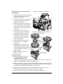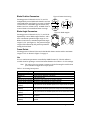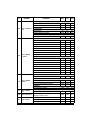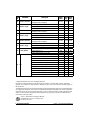
1
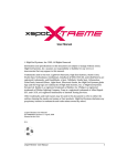
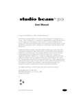
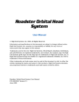
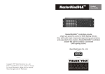
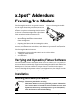
x.Spot™ Addendum:
Framing/Iris Module
The Framing/Iris module is an optional accessory
for the x.Spot fixture that provides accurate and
repeatable beam shape control on walls and stage
elements. It replaces the Rotating Gobo/Iris module
in Slot 3 of a standard configuration x.Spot fixture.
Figure 1 Framing/Iris Module
This Addendum includes instructions for:
•
Installing the Framing Module
•
Reassembling the modules into standard
fixture configuration
•
Operating the fixture with the Framing/Iris module
Refer to the x.Spot User Manual (p/n 60600174) for additional safety, compliance,
warranty, and maintenance information, and all other x.Spot features and operation.
The Framing/Iris Module features:
•
Independent position and angle control on each of four blades.
•
±45-degree frame rotation
•
A Variable Iris
Verifying and Uploading Fixture Software
The x.Spot fixture must be running the latest version of software (3.0.0 or greater) to
ensure the fixture automatically recognizes the Framing/Iris module and modifies the
DMX protocol. The latest software for x.Spot fixtures is available in the support
section of the High End Systems® web site (www.highend.com). See Chapter 2 of the
x.Spot User Manual for directions on uploading the latest software to the fixture.
Installation
Installing the Framing/Iris Module
Warnings: Disconnect power before servicing.
This fixture must be serviced by qualified personnel. Information
listed in this chapter is intended to assist qualified personnel only.
Equipment surfaces may reach temperatures up to 130°C (266°F).
Allow the fixture to cool before handling.
x.Spot™ User Manual Addendum
Framing/Iris Module 1
Open the Fixture:
1.
Remove the bezel by loosening the three (3) captive screws on each side of the
fixture head with a flathead screwdriver. Lift the bezel sides away from the base
and toward the lens (see Figure 2).
When replacing the bezel, ensure that it is fitted securely in the yoke channel on
both side of the fixture as shown in Figure 2.
Figure 2 Removing and replacing the bezel
Captive
Screws
Bezel channel in
yoke arm
Remove the Slot 3 Gobo/Iris Module
Figure 3 Removing Slot 3 Module.
(Refer to Figure 3 for Steps 2–4).
2.
With the lens pointed up, rotate the
fixture so the tilt belt (A) is on your
left. Locate the Rotating Gobo and
Iris Module in Slot 3 (closest to the
lens) and gently move the module
toward the lens until the linear slide
(B) reaches its limit.
3.
Detach the IDC connector (C) from
the Slot 3 module’s driver board.
4.
Loosen the two captive screws (D)
on the Rotating Gobo and Iris
module and pull it straight out of the
unit.
2 Framing/Iris Module
E
B
F
C
A
D
x.Spot™ User Manual Addendum
Reconfigure the Slot 2 Dual Rotating
Gobo Module.
5.
Detach the IDC connector (C in Figure
4) from the Dual Rotating Gobos
Module driver board.
6.
Loosen the two captive screws on the
module (D in Figure 4) and pull it
straight out of the unit.
7.
Referring to Figure 5 for Steps 7–12,
use a 2mm (1/64in.) allen wrench to
loosen the set screw on the Gobo 1
wheel. Lift it, and the washer below it
off the hub.
8.
Loosen set screw and remove 90tooth gear and the washer below
it from shaft. Retain to reinstall.
9.
Figure 4 Removing Slot 2 Module.
E
C
D
B
Figure 5 Reconfiguring Dual Rotating
Gobo Module
Without loosening the set screw,
lift the Effects wheel assembly,
attached gears, and the washer
below it off the hub.
10. Loosen the set screw and remove
the drive gear with a stepped
sensor tab.
11. Reposition the 90-tooth gear on
shaft aligning the top of the gear
hub with the outer shaft. Tighten
Effects Wheel
set screw and place washer on
Assembly
shaft over gear.
12. Replace Gobo 1 on shaft and
tighten set screw.
A
F
Gobo
Gobo
Washer Wash
90-tooth
Gear
Gea
Effects
Orient
gear
Effects
Wheel
ongobo
shaftrotate
Remove drive gear
Install the Module
13. Referring to Figure 4, slide the
reconfigured Rotation Gobo
module back into the slot 2
position using aligning pins (E) and channel guides (F) to orient it. Tighten the
captive screws (D) and reattach IDC connector (C).
14. Referring to Figure 3 on page 2, slide the assembled Framing/Iris module into the
slot 3 position using aligning pins (E) and channel guides (F) to orient it. Tighten
the captive screws (D) and reattach IDC connector (C).
15. Reattach the bezel guiding it into the bezel channel on each yoke arm and
retighten captive bezel screws as shown in Figure 2 on page 2.
16. Connect the fixture to power. The fixture will automatically home.
x.Spot™ User Manual Addendum
Framing/Iris Module 3
Returning Fixture to Standard Configuration
To restore the x.Spot fixture to standard configuration:
1. Follow Steps 1-6 in the preceding section to remove Slots 2 and 3 modules.
2. Referring to Figure 5, use a 2mm (1/64in.) allen wrench to loosen the set screw on
the Gobo 1 wheel. Lift it and the washer below it off the hub.
3. Loosen set screw and remove 90-tooth gear and the washer below it from shaft.
4. Reinstall the saved drive gear on the plate. Do not tighten set screw.
5. After moving sensor tab outside of path, replace washer and effects wheel
assembly with attached gears on shaft.
6. Raise the drive gear up and align with the first gear under the effects wheel. Ensure
that the sensor tab moves freely and tighten the set screw, (see Figure 6).
7. Replace washer and 90-tooth gear
on shaft and tighten set screw.
8. Replace Gobo 1 wheel and tighten
set screw.
9. Go to section “Install the Module”
on page 5-3 to complete installation.
Figure 6 Drive Gear Alignment
Gear alignment
Effects
wheel
+ gears
Sensor
tab
Module Operation
The fixture automatically recognizes the Framing/Iris module when it homes and
adjusts the menu system settings to Framing/Iris parameters. For information on
operating the fixture with the onboard menu system, see Chapter 3 of the x.Spot User
Manua). Chapter 4 of the x.Spot User Manual contains parameter descriptions for
use with a DMX controller. Channels 1-22 parameters remain the same in this
configuration of the fixture (see Appendix A of the x.Spot User Manual). The
remainder of this addendum describes DMX parameters and channel assignments
specific to the Framing/Iris module.
Figure 7 Module Orientation
Parameter Descriptions
The following descriptions assume the
module is in the homed position and
viewed as shown in Figure 7. Blade
numbering also reflects this orientation.
Blade position and angle ranges are the
same for opposite blades.
Blades
1
3
4
2
Frame Rotation
4 Framing/Iris Module
x.Spot™ User Manual Addendum
Blade Position Parameters
Framing protocol Channels 28, 30, 32, and 34
independently control blade movement in and out
of the light beam (see Figure 8 on page 5). Blades
1 and 2 close to a minimum gap of 10mm(.4in);
blades 2 and 4 to .25mm(.01in). A DMX value of
0 sets a blade to its maximum beam coverage.
Blade Angle Parameters
Framing protocol Channels 29, 31, 33, and 35 independently control Blade angle. Blades 1 and 2
have a maximum potential angle range of ±14°.
Blades 3 and 4 have a maximum potential angle
range of ±32° (see Figure 9). The potential angle
range will be affected by the position parameter
setting for that blade.
Figure 8 Blade Positioning
.25mm
1
3
10m
4
2
Figure 9 Blade Angles
1
3
4
2
Frame Rotate
Framing protocol Channel 36 controls the Module frame rotation with a maximum
range of ±45° as shown in Figure 7 on page 4.
Iris
Iris is a continuous parameter controlled by DMX Channel 37. The iris utilizes a
variable circular opening to control the beam diameter. See Table 1 for Iris settings.
Note: The range of iris movement is greater with the Framing/Iris module than
for a standard configuration x.Spot fixture.
Table 1 Iris Setting Descriptions
Iris Setting
Close
Variable Iris
Open
Periodic Strobe (Variable)
Random Strobe (Variable)
Ramp Open/Snap Shut
(Variable)
Snap Open/Ramp Shut
(Variable)
Ramp Open/Ramp Shut
(Variable)
Random Ramp/Snap
(Variable)
Random Snap/Ramp
(Variable)
Description
Closes the iris.
Determines the diameter of the beam.
Fully opens the iris.
Strobes the beam diameter at specified intervals.
Strobes the beam diameter at random intervals.
Fully opens the iris at variable speeds, then snaps shut at full speed.
Fully opens the iris at full speed, then ramps shut at variable speeds.
Fully opens the iris at variable speeds, then shuts at the same speed.
Fully opens the iris at variable, random speeds, then snaps shut at
full speed.
Fully opens the iris at full speed, then ramps shut at variable, random
speeds.
x.Spot™ User Manual Addendum
Framing/Iris Module 5
Framing/Iris Module DMX Protocol
An x.Spot fixture configured with a Framing/Iris Module requires a 37 DMX Channel
range instead of the 38 Channel range of a standard configuration x.Spot fixture.
Table 1 shows DMX protocol specific to the Framing Module and reflects the
reduction in DMX channel requirements.
Use this protocol to replace channels 23–38 of a standard configuration x.Spot
fixture. All other Channel parameters remain the same as the standard configuration,
(see Appendix A of the x.Spot User Manual).
Table 1
Framing Module DMX Protocol
Chan
#
Parameter
Description
Value
(dec.)
SLOT 2/3: FRAMING AND IRIS MODULE
Full Speed Control
Indexed
0 - 15
Forward Wheel Spin
16-31
Reverse Wheel Spin
32-47
Scan
48-63
Random
64-79
Blink
80-95
TBC
96-111
Continuous
112-127
23 Gobo1 Function
MSpeed Control
Indexed
128-143
Forward Wheel Spin
144-159
Reverse Wheel Spin
160-175
Scan
176-191
Random
192-207
Blink
208-223
TBC
224-239
Continuous
240-255
Indexed /Blink/Scan Modes
Position 1 (Open)
0-15
Position 2
16-47
Position 3
48-79
Position 4
80-111
24 Gobo 1 Position
Position 5
112-143
Position 6
144-175
Position 7
176-207
Position 8
208-239
Position 1 (Open)
240-255
6 Framing/Iris Module
Value
(%)
Value
(hex)
0-6
6-12
13-18
19-25
25-31
31-37
38-44
44-50
0-0F
10-1F
20-2F
30-3F
40-4F
50-5F
60-6F
70-7F
50-56
57-62
63-69
69-75
75-81
82-88
88-94
94-100
80-8F
90-9F
A0-AF
B0-BF
C0-CF
D0-DF
E0-EF
F0-FF
0-6
6-18
19-31
31-44
44-56
57-69
69-81
82-94
94-100
0-0F
10-2F
30-4F
50-6F
70-8F
90-AF
B0-CF
D0-EF
F0-FF
x.Spot™ User Manual Addendum
Chan
#
24
25
26
27
28
29
Parameter
Description
Spin Mode
Spin Stop
Spin Forward Slowest to Fastest
Spin Reverse Slowest to Fastest
Gobo 1 Position,
Random Mode
cont.
Random Stop
Random Slowest to Fastest
Continuous Mode
Positioning from 1-360 degrees
Full Speed Control
Indexed
Forward Rotate
Reverse Rotate
Scan
Blink
Reserved
Reserved
Reserved
Gobo 1 Rotate
Function
MSpeed Control
Indexed
Forward Rotate
Reverse Rotate
Scan
Blink
Reserved
Reserved
Reserved
Indexed /Scan/Blink Modes
Position 0-360 degrees
Rotate Mode
Rotate Stop
Gobo 1 Rotate
Coarse
Forward Rotate Slowest to Fastest
Reverse Rotate Slowest to Fastest
Scan Mode
Scan Slowest to Fastest
Indexed Mode
Gobo 1 Rotate
Fine
Low Order Byte 0-360 degrees
Adjusts blade position from maximum beam
Blade 1 Position
coverage to full out (open)
Blade Angle Negative from –14° to –1°
Blade 1 Angle
Blade Angle 0 degrees
Blade Angle Positive from +1° to +14°
x.Spot™ User Manual Addendum
Value
(dec.)
Value
(%)
Value
(hex)
0-3
4-255
4-255
0-1
2-100
2-100
0-3
4-FF
4-FF
0-3
4-255
0-1
2-100
0-3
4-FF
0-255
100
FF
0-15
16-31
32-47
48-63
64-79
80-95
96-111
112-127
0-6
6-12
13-18
19-25
25-31
31-37
38-44
44-50
0-0F
10-1F
20-2F
30-3F
40-4F
50-5F
60-6F
70-7F
128-143
144-159
160-175
176-191
192-207
208-223
224-239
240-255
50-56
57-62
63-69
69-75
75-81
82-88
88-94
94-100
80-8F
90-9F
A0-AF
B0-BF
C0-CF
D0-DF
E0-EF
F0-FF
0-255
0-100
0-FF
0-3
4-255
4-255
0-1
2-100
2-100
0-3
4-FF
4-FF
0-255
0-100
0-FF
0-255
0-100
0-FF
0-255
0-100
0-FF
0-127
1-49 01-7F
128
50
80
129-255 51-100 81-FF
Framing/Iris Module 7
Chan
#
Parameter
30 Blade 2 Position
31 Blade 2 Angle
32 Blade 3 Position
33 Blade 3 Angle
34 Blade 4 Position
35 Blade 4 Angle
36 Frame Rotate
37 Iris
Description
Adjusts blade position from maximum beam
coverage to full out (open)
Blade Angle Negative from –14° to –1°
Blade Angle 0 degrees
Blade Angle Positive from +1° to +14°
Adjusts blade position from maximum beam
coverage to full out (open)
Blade Angle Negative from –32° to –1°
Blade Angle 0 degrees
Blade Angle Positive from +1° to +32°
Adjusts blade position from maximum beam
coverage to full out (open)
Blade Angle Negative from –32° to –1°
Blade Angle 0 degrees
Blade Angle Positive from +1° to +32°
Frame rotation from –45° to 1°
Frame rotation = 0
Frame rotation from +1° to +45
Closed
Variable Iris
Open
Periodic Strobe (Variable)
Random Strobe (Variable)
Ramp Open/Snap Shut (Variable)
Snap Open/Ramp Shut (Variable)
Ramp Open/Ramp Shut (Variable)
Random Ramp/Snap (Variable)
Random Snap/Ramp (Variable)
Open
Value
(dec.)
Value
(%)
Value
(hex)
0-255
0-100
0-FF
0-127
1-49 01-7F
128
50
80
129-255 51-100 81-FF
0-255
0-100
0-FF
0-127
1-49 01-7F
128
50
80
129-255 51-100 81-FF
0-255
0-100
0-FF
0-127
128
129-255
0-127
128
129-255
0
1-127
128-135
136-151
152-167
168-183
184-199
200-215
216-231
232-247
248-255
1-49
50
51-100
1-49
50
51-100
0
1-50
50-53
53-59
60-66
66-72
72-78
78-84
85-91
91-97
97-100
01-7F
80
81-FF
01-7F
80
81-FF
0
01-7F
80-87
88-97
98-A7
A8-B7
B8-C7
C8-D7
D8-E7
E8-F7
F8-FF
© High End Systems, Inc. 2002, All Rights Reserved
Information and specifications in this document are subject to change without notice. High End
Systems, Inc. assumes no responsibility or liability for any errors or inaccuracies that may appear in
this document.
Trademarks used in this text: High End Systems, the High End Systems globe logo, and LithoPatterns
are registered trademarks; and x.Spot is a trademarks of High End Systems, Inc. Other trademarks
and trade names may be used in this document to refer to either the entities claiming the marks and
names or their products. High End Systems disclaims any proprietary interest in trademarks and
trade names owned by others.
x.Spot™ Addendum: Framing/Iris Module
P/N 60600205 Version 1.0 January, 2002
Printed in the USA
8 Framing/Iris Module
x.Spot™ User Manual Addendum