1
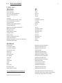
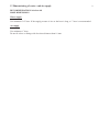
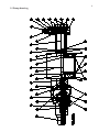
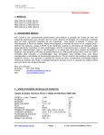
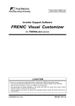
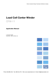
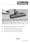
AIRCLEAN 48
High-pressure cleaner
USER MANUAL
Produced in Norway for:
Wilhelmsen Ships Service
Contents
E.1 IMPORTANT INFORMATION
3
E.2 DESCRIPTION AND OPERATION
4
E.3 MAINTENANCE
5
E.4 ENCLOSURES
8
E.1.1 Safety
E.1.2 Lubrication
E.1.3 Air operating pressure
E.1.4 Frost protection
E.1.5 Guarantee
3
3
3
3
3
E.2.1 Pump unit
E.2.2 Water inlet
E.2.3 Air inlet
E.2.4 Chemical dosing
E.2.5 Cleaning procedures
E.2.6 Accessories
4
4
4
4
4
5
E.3.1 Preventive maintenance
E.3.2 Pump Unit Dismantling
E.3.3 Change of pump piston seal
E.3.4 Pump valves
E.3.5 Valve shuttle
E.3.6 Valve rod sealing
E.3.7 Fault diagnosis
E1
E2
E3
E4
5
5
6
6
6
6
7
Data sheet
Dimensioning of water- and air supply
Part list
Pump drawing
8
9
10
11
Airclean48/TF/02.11.2007
E.1 IMPORTANT INFORMATION
3
E.1.1 Safety
Never point the gun at yourself or anybody else and hold it with both hands when spraying. A highpressure spray can penetrate the skin causing serious injury.
Before service work, always disconnect the air supply.
When cleaning, it is strongly advisable to use protective goggles, wear protective gloves and protective
clothing.
Never spray electrical equipment or cables unless you are sure that the installation stands high-pressure
cleaning.
Be sure that any part to be fitted withstands the pressure.
If the cleaning unit is to be used in a hazardous environment, earthing the equipment will eliminate
static electricity.
Airclean is CE-marked.
E.1.2 Lubrication
The air motor requires lubricated air. In order to ensure uninterrupted steady operation you must never
let the fitted air lubricator run dry. The correct position of the adjustment screw is approx. 1/2-1 turn.
E.1.3 Air operating pressure
Do not exceed maximum safe air operating pressure specified in data sheet, enclosure 1.
E.1.4 Frost protection
If frost is expected, the waterside must be emptied to prevent damage by frost. This is simple. Disconnect the water supply and let the unit run some strokes until the pump, hose, spray gun and extension
tube is empty. Or change over the air supply to the water intake and blow the waterside dry.
E.1.5 Guarantee
The guarantee is not valid for damages caused by erroneous usage or if the unit has been disassembled
without written permission from the manufacturer.
E.2 DESCRIPTION AND OPERATION
4
E.2.1 Pump unit
The pump unit comprises a single acting pump powered by a double acting air motor. An air shuttle
valve that changes the air direction when the piston reaches the end positions controls the air motor.
E.2.2 Water inlet
The connection is marked “Water”. Use a water supply hose with minimum diameter as specified in
enclosure 2 “Dimensioning of water- and air inlet”. It is recommended to connect a low-pressure hose
of minimum 3 meters length to the water inlet of the unit to prevent shock in the water system.
The suction head capacity of the pump is reduced with increasing temperatures. Increased supply pressure may therefore be required when pumping hot water. The suction line must be free from leeks.
Claw couplings are not suitable for suction lines with pressures below atmospheric pressure.
E.2.3 Air inlet
The air connection is marked “Air”. Use air supply hose with minimum diameter as specified in enclosure E.2 “Dimensioning of water- and air inlet”. Do not fit valves, fittings etc. with less diameter than
specified in enclosure E.2. If regulation is required at the unit, it is recommended to fit a full-bore ball
valve and use this for throttling the air supply. If you are going to use an air pressure regulator it must
be plentiful dimensioned for the airflow.
E.2.4 Chemical dosing
A high-pressure injector fitted between the high-pressure pump outlet and the high-pressure hose may
dose chemicals. You may need to turn down the water pressure by throttling the air motor to achieve
that the injector will work properly. We recommend to disconnect the injector when not in use because
it “steals” pressure.
E.2.5 Cleaning procedures
Hot water, if available, will always give the best result and reduces the need for chemicals. The following procedures are recommended to get the best result when working with detergents:
- Apply the detergent with a wide-angle spray. Start at the bottom and move upwards. The spray
distance should be approximately 40 cm.
- Leave the detergent to work approx. 3 minutes, or according to the manufacturer’s instructions.
However, do not let detergent dry on the surface.
- Start cleaning from the bottom and move upward. This prevents water to run down and dilute
detergent below. The spraying distance should be 10 – 30 cm.
- When cleaning is completed, wash down from the top to prevent stains. Use water generously.
E.2.6 Accessories
5
The Airclean standard scope of supply is tailored to cater for ordinary cleaning tasks in an efficient and
economic manner. Special demands are met by made suit accessories, which may be procured when
needed. Such accessories include:
- Chemical injector.
- Turbo nozzles and other nozzle types.
- Sand blasting set for cleaning and de-scaling rusty steel structures etc.
- Nozzles for opening clogged tubes.
- Foam set for soap, disinfectants etc.
- Air filters, water filters, couplings for water and air.
- Extension tubes and extra hoses.
- Airclean wheel lance. Complete lance system for efficient washing of high walls, ceilings etc.
- Hose drums.
E.3 MAINTENANCE
E.3.1 Preventive maintenance
Preventive maintenance is limited to filling of lubrication oil, visual inspection and cleaning. Particular
attention should be paid to high-pressure leaks and high-pressure hose. High-pressure leaks should be
repaired straight away as they may increase rapidly if left unattended. The method of repair depends on
where the leaks occur:
a. Pump Seal
A leak pump piston seal will cause a flow of water out of the drain hole on the bottom
side of the pump cylinder.
b. Threads
All threads are BSP standard. The sole exception is the spray nozzle, which is NPT. All
threads are assembled with sealing liquid, and leaks will normally never occur. However, if leaks should occur the threads must be cleaned and reassembled using either a
sealing liquid or thread tape.
c. High-pressure hose couplings
The high-pressure hose couplings have metal-to-metal seals. To stop a leak, tighten the
nut until the leak stops. If this does not work, open the coupling and inspect the sealing
surfaces.
High pressure cleaning is the best method for cleaning the unit.
If the plant air is contaminated, for instance by rust, an air filter should be fitted. A water filter should
be fitted if the water contains abrasive particles.
E.3.2 Pump Unit Dismantling
The pump unit is assembled by means of lock rings and may be split at A or B (Pump unit drawing).
For access to the pump piston seal undo the tie bolts.
E.3.3 Change of pump piston seal
a.
b.
c.
d.
Loosen the attaching bolts.
Pull the cylinder of the piston.
Check the cylinder for scratches to see if honing or a replacement is required.
Remove the lock pin for the front part of the piston and screw it off. Fit o-ring, pump seal and
front part of the piston.
e. Fit new slide rings.
f. Lubricate piston, seal and slide rings to ease reassemble and prevent damages at start up.
Reassemble sequence is opposite to dismantling, but note the following:
g. Tighten the attaching-bolts two and two opposite at a time. Sealing liquid should be applied to
the bolts.
E.3.4 Pump valves
The valve seats are fixed and are not removable. Proceed as follows to inspect/renew balls or springs:
a. Undo attaching bolts and pull free the pump head to gain access to the inlet valve. The outlet
reducer is fitted with sealing liquid.
b. Clean and inspect parts. Remove loose scale etc. Replace worn parts.
c. Clean threads.
d. Fit parts according to drawing.
e. Use sealing fluid on outlet reducer threads when assembling. Tighten opposite bolts to avoid
skewing.
E.3.5 Valve shuttle
a. Unscrew threads end cover, remove dampening ring and pull out the valve shuttle.
b. Dismantle, clean, inspect and replace parts as required.
c. Re-assembly is done in reversed order. Screw in and end cover till it bottoms.
E.3.6 Valve rod sealing
a.
b.
c.
d.
Split pump unit by pulling lock ring B (See drawing)N5.
Dismantle, clean, inspect and replace worn parts as required.
Lubricate all o-rings prior to re-assembly.
Re-assembly is done in reversed order.
6
E.3.7 Fault diagnosis
Symptom
1. Low delivery/pressure
2.
3.
4.
5.
6.
7.
8.
9.
Possible Cause and Solution
a) Restricted air supply.
See E.2.3 “Air inlet”.
Clean filters in the air supply.
Open closed valves.
b) Inadequate air supply capacity.
Check compressor capacity.
(See data sheet).
Wrong nozzle bore. Change nozzle.
Worn out nozzle. Change nozzle.
Uneven operation
a) Inadequate lubrication.
b) Insufficient air supply
Pump failure to start
a) Pressure gauge on unit shows there is
pressure: Clogged nozzle. Disconnect air
supply and check for ice plug.
b) Pressure gauge on unit shows no pressure:
Closed air supply.
Clogged air supply.
No pressure in the air system.
Pump runs without delivery or low deliv- a) Closed water supply.
ery
Check any valves and filters in the supply.
b) To large suction head.
c) Undersized valves/fittings in the supply.
d) Blocked/restricted air supply.
e) Leaking pump piston seal.
Water/air leakages
a) Defect pump piston seal or other seals
Pump over-speeds with no or low delivery a) Lacking or no water supply.
Check valves and filters.
b) To high suction head.
c) Restrictions in water supply.
d) Leaking pump piston seal.
Pump runs after trigger is released
a) Pump inlet valve is damaged or blocked
in open position.
b) Leaking pump piston seal.
Pulsating spray
a) Leaking suction line.
b) Only 1 pump is working
Air motor stops and blows air
a) Damage to o-ring seal(s) on air motor.
Seals must be changed.
7
E.4 ENCLOSURES
E1Data sheet
8
Airclean
48
No of cylinders
2 pcs
Air motor cylinder diameter
125 mm
Pump cylinder diameter
18 mm
Stroke
75 mm
Capacity
0-19 l/min
Air consumption (free air, 1 bar)
0-9 m3/min(150 l/s)
Recommended air pressure
5-11 bar
Pump pressure
0-480 bar
Maximum inlet water pressure
25 bar
Suction head up to
4m
Maximum inlet water temperature
150 °C
Water inlet nozzle
3/4’’ BSP female
Air inlet nozzle
3/4’’ BSP male
High pressure outlet
3/8’’ BSP male
Length overall
720 mm
Width overall
520 mm
Height overall (pump cart)
980 (540) mm
High pressure hose
3/8’’x10 m
Weight complete incl. hose, gun and lance
59 kg
Extension tube lenght
800 mm
Pressure ratio
48 : 1
MATERIALS
Pump head
Nickel and chrome plated st
Pump valve seats
Stainless steel AISI 316
Pump valve springs
Stainless steel AISI 301
Pump piston seal
PTFE/Carbon
Piston rod
Stainless steel AISI 303
Valve ball
Stainless steel AISI 420B
Pump cylinder
Stainless st. SS2387. Hard.
Air cylinder
Nickel and chrome plated st
Valve rod
Stainless steel AISI 303
Frame
Nickel and chrome plated st
Tube parts
Galvanized steel
Cover
Vacuum formed ABS
Bolts
Hot galvanized steel
Spray gun
Stainless steel/plastic
Extension tube
Stainless steel AISI 316
High pressure nozzle
Stainless steel AISI 316
The unit will be delivered complete with
10m high pressure hose with spray gun,
extension tube, spray nozzle, press. gauge,
air lubricator and exhaust air muffler.
Subject to be improved without notice
E2Dimensioning of water- and air supply
RECOMMENDATIONS Airclean 48
HOSE DIMENSIONS
Water supply
Use minimum 3/4’’ hose. If the supply pressure is low or the hose is long, a 1’’ hose is recommended.
Air supply
Use minimum 1’’ hose.
Do not fit valves or fittings with less inner diameter than 19 mm.
9
10
E3Part list
AIRCLEAN 48
PART NO U1200 PUMP UNIT
Part No
P1002
P1037
P1003
P1204
P1157
P1106
P1007
P1008
P1019
P1010
P1040
P1012
P1005
P1041
P1042
P1119
P1035
P1043
P1044
P1045
P1024
P1123
P1026
P1025
P1159
P1158
P1166
P1027
P1134
P1267
P1016
P1164
P1236
P1168
P1080
P1081
P1082
P1083
P1084
Description
Pump head
Hex nut
Stud screw
Piston rod
Glide ring
Air piston
Valve ball
Hex screw
Reduser
Spring
Pump cylinder
Cylinder cover
Spring
Pump piston
Glide ring
Ring
End cap
Pump packing
O-ring
O-ring
O-ring
O-ring
O-ring
O-ring
O-ring
Liner
Sleeve
Air cylinder
Valve shuttle
Valve housing
Snap ring
Sleeve
Valve rod
O-ring
Elbow
Hose nipple
Return line
Hose clip
Adapter
Pos no Qty.
1
1
2
1
3
1
4
1
5
1
6
1
7
2
8
4
9
1
10
1
11
1
12
1
13
1
14
1
15
2
16
2
17
1
18
1
19
1
20
1
21
5
22
2
23
6
24
6
25
6
26
1
27
1
28
1
29
1
30
1
31
2
32
1
34
1
35
1
36
3
37
2
38
1
39
2
40
1
11
E4Pump drawing