1
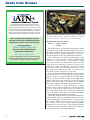
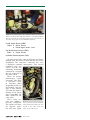
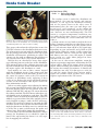
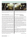
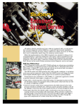
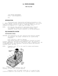
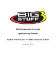
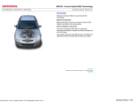
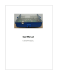
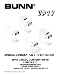
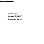
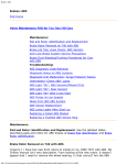
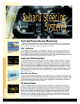
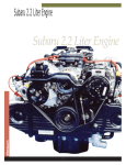
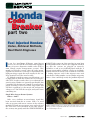
Honda
Code
part one
Breaker
part two
Fuel Injected Hondas:
Codes, Retrieval Methods,
Real World Diagnoses
n our last installment (February 1999 Import
Service), we covered ECU locations and explained
how to recover diagnostic trouble codes (DTC’s)
from Honda engine management systems. This
month we’ll discuss exactly what the codes mean,
explain why and how a code can set and identify the
high-percentage repair that will usually fix the car.
Keep in mind I used the word usually.
It’s difficult to make accurate generalizations, so it
is impossible to name the actual cause of every possible DTC. In other words, there is no substitute for
actual testing. Hondas are generally predictable, but
I wouldn’t bet the farm on a hunch or on what happened yesterday. If you’ve tried my suggestions and
still have a problem, get the meters out and run the
voltage tests. You'll fix the car right, and you’ll learn
something too.
I
PGM-FI light comes on, then run fine in open loop
or limp-home mode. If that is the symptom, check to
see that the sensors are plugged in correctly.
Cylinders 1 and 4 are feedback-paired with the A
oxygen sensor while cylinders 2 and 3 are feedbackpaired with the B sensor. Code 2 could be caused by
a leaking injector, and if that injector were now
switched to either number 1 or 4 cylinder, triggering
Code 1, that could help verify the problem injector.
Single Wire Oxygen Sensor Systems
Codes: 1 And 2
Code 1 or 2 indicate an out-of-range signal has
been received from the 02 sensor. Code 2 is used
only on systems with two 02 sensors in the exhaust
manifold. If both oxygen sensors were replaced and
the lead wires were switched on the two sensors,
the car may run poorly until the CHECK ENGINE or
24
Figure 1: Early models use a single wire zirconia oxygen sensor.
Things got more complicated with later four and seven-wire sensors and multiple sensors.
March 1999
Honda Code Breaker
02 sensor activity, or lack of it, is what sets the
code. The parameters the ECU is looking for are:
the 02 sensor voltage should be over 0.6 volts
under WOT conditions and under 0.4 volts during
closed throttle decel. At other throttle angles, a
good 02 sensor may ‘crosscount’ as often as three
times per second if viewed on a scope with the
engine speed at approximately 3000 rpm. If the
TPS is set correctly, your meter may show 0.0
volts briefly as the engine decels in ‘fuel-cut’
mode (closed throttle above 1200 rpm) after snapping the throttle open.
There is approximately a 0.5 volt bias on the
signal wire from the 02 sensor to the ECU. With the
02 sensor unplugged, the value on the harness side
of the connector should read approximately 0.5
volts with the key on. If it reads 0.0 volts, unplug
the ECU and check the wire for continuity to
ground, if none is present, secure the connection
at the ECU. If it reads high, check for a poor
ground at the ECU.
1986-1987 CRX Si and Civic Si systems may set
Code 1 from an unusually high quantity of fuel
vapors purged from the charcoal canister during
cruise conditions. While this might be construed as
emissions tampering, a Honda motorcycle carburetor main jet (Honda P/N 2466555) inserted in the
braided red purge hose at the top of the throttle
body effectively meters the volume of canister
purge to a manageable rate.
At cruise conditions, the 02 voltage should be
neither unusually high (which could indicate
overfueling), or too low (which could be caused by
clogged injectors or low fuel pressure). Backprobe
the 02 sensor wire, using care not to also pierce the
shield, then drive the car. You should see the 02
sensor voltage rise and fall under accel and decel
conditions respectively, and crosscount at idle and
cruise conditions.
Oil or coolant contamination on the atmospheric
port of the 02 sensor may kill the sensor. If a visual
examination shows oil or any other contaminant at
the oxygen sensor, repair the contaminant source,
and replace the sensor. Coolant may wick down
from the ground attachment point at the thermostat
housing toward the 02 sensor. Repair the leak and
replace the sensor.
Four-Wire Oxygen Sensor Systems
Codes: 1 P0131, P0132
41 P0135, P1166, P1167
43
Code 1 and 43 are basically the same as the oxygen sensor codes on the single wire systems. The
four-wire sensors use an electric heater, however.
There is a 12 volt key-on supply voltage to the
26
sensor, and the sensor ground is controlled by the
ECU. The two wires on the sensor side of the connector correspond to heater power and ground.
These wires are usually black. If a Code 41
appears (four long flashes and one short flash at
the end), check the two black wires on the 02 sensor side of the connector for continuity. Typically
you’ll find a 20-40 ohm reading on a good heater
circuit. If the sensor circuit is open, replace the
02 sensor.
Code 1 indicates an oxygen sensor problem, while
the service manual calls Code 43 a ‘fuel system’
code. There’s no explanation why the ECU sets a
Code 43 instead of a Code 1. For Code 43 the manual instructs you to look for things like leaking
injectors, etc., which could also cause a Code 1.
Don't worry about what number is displayed. The
ECU just told you it doesn't like the 02 sensor, so
we’ll leave it at that.
The nice thing about heated 02 sensors is the car
doesn't have to be running to see what's what.
This heater can get the oxygen sensor warm
enough to recreate a driven, warmed-up vehicle
condition. Unplug the 02 sensor connector and
check with the key on and a test light for the
twelve volt power source, usually a B/Y or Y/B
wire. Now with the sensor plugged in, ground the
other wire in the connector that corresponds to
the other black wire of the 02 sensor. This will turn
the heating element on.
The four-wire oxygen sensor still uses the same
0.5 volt bias voltage on the oxygen sensor signal
wire. If we monitor that voltage with the key on
and the heater activated, we should see 0.4-0.5
volts just as the key is turned on. That voltage
should slowly fall to less than 0.1 volts within two
minutes. If the engine is not running, there should
be 21 percent 02 in the exhaust manifold, which
would make an 02 sensor read very low. If the value
stays at 0.5 volts and drops very slowly or not at
all, replace the 02 sensor.
Seven-Wire Oxygen Sensor Systems
Code: 48 P1162, P1168, P1169
The seven-wire system is actually a linear air fuel
ratio sensor, rather than an oxygen sensor in the traditional sense. Using this sensor as an input, the
ECU can control the fuel mixture at 14.7 to 1 for
most driving conditions, or at 22 to 1 for optimal
fuel economy under ideal conditions. This sensor
uses multiple heaters, and the book tests don't really give any insight as to what's occurring as far as
tangible values. In most cases, replacement of the
sensor is required if a problem is detected. Sensor
replacement may become necessary with as little as
30,000 miles on the vehicle.
March 1999
Honda Code Breaker
The International Automotive Technicians’ Network is a group
of 18,727 professional automotive technicians from all over the world.
The automotive technician members of this group exchange technical
knowledge and information with fellow iATN members. The combined
knowledge of thousands of top industry professionals networking
together helps the professional members of this group to provide the
highest quality automotive repair, diagnosis and service in the world.
If you are a professional automotive technician
and would be interested in networking with other
automotive professionals from all over the world,
point your browser to
h t t p : / / w w w. i a t n . n e t
where you will find iATN Membership
Information and Requirements.
iATN Mission of Excellence
“To promote the continued growth, success and image of the Professional
Automotive Technician by providing a forum for the exchange of knowledge
and the promotion of education, professionalism, and integrity.”
28
Figure 2: The plastic cover has been removed to get a glimpse of
the MAP sensor and other EFI-related components mounted
inside the control box on this early Accord PGM-FI model.
Manifold Air Pressure Sensor
Codes: 3 P0107, P0108
5 P0106
The MAP sensors are located in the black box on the
firewall on early models and bolted directly on top of
the intake manifold on some later models. The hose to
the MAP sensor is always numbered 21 unless it's
directly mounted to the top of the intake manifold.
Code 3 indicates an electrical malfunction of the
MAP sensor. There are three wires to Honda MAP
sensors: a 5 volt reference, a ground and a signal
wire. The signal wire should read about 2.9 volts
with the key on and drop to about 0.8 volts at idle
with 20-21 inches of manifold vacuum. If the output voltage reads as it should at the sensor, check
the output wire right at the ECU. A signal of near
zero volts or over 4.0 volts sets the code.
Code 5 indicates a problem with the vacuum circuit.
This means the ECU is receiving the correct voltage
values, but they are not changing. If the MAP sensor
hose is cut, this code will set because the output value
did not change once the engine was started. Damaged
MAP sensor hoses (where it attaches at the throttle
body) are a common occurrence on 1988-91 Civics.
A code could be set if the TPS shows a closed
throttle voltage with an idle rpm value but the ECU
sees 2.9 volts from the MAP sensor. The small orifice in the MAP sensor where the hose attaches may
clog. If the MAP sensor bolts to the intake manifold,
a carbon buildup may clog the opening.
On models with the MAP sensor on the intake manifold, the TPS connector and MAP connector have the
same configuration, and the harness connectors may
be switched. While this may not set a code because
the voltages will still be within normal operating
parameters, it will sure cause a driveability problem.
Look for this error if engine work has been done and
you can't identify a driveability problem.
March 1999
Figure 3: The bottom half of this distributor has been disassembled to reveal the CYL and TDC reluctors. A no-start condition
may be caused by a rusted roll pin that secures the reluctors to
the shaft. These parts are not available separately.
Crank Angle Sensor (CRK)
Codes: 4 P0335, P0336
8 P1359 Open, P1361, 1362
Top Dead Center Sensor (TDC)
Code: 9 P1381, P1382
Cylinder Position Sensor (CYL)
On 1985-89 Accords, 1985-87 Preludes and Civics
through 1987, this sensor is built into the base of the
distributor. The four-wire connector has very
a distinctive terminal arrangement. Two vertical
terminals serve one
sensor, and the two
remaining horizontal
terminals in a straight
line are connected to
the other sensor.
These are permanent-magnet
signal
generators. They have
a resistance value
of 300-1000 ohms
(depending on the year
and model), and produce at least 200 mv
AC when the engine is
running. If one sensor
spec is 500 ohms, the
other should be the
same value.
These early systems may exhibit a Figure 4: CYL and TDC wiring harno-start condition. ness connector. The two terminals
The engine will have facing toward each other are conno injector pulse nected to the TDC sensor, the
but will have spark. others to the CYL sensor.
March 1999
Honda Code Breaker
Coolant Sensor (TW)
Code: 6 P0117 Low Input,
P0118 High Input
Figure 5: The permanent magnet CYL and TDC sensors inside
the lower half of the distributor are electrically identical and
should both produce the same resistance reading.
This occurs when when the roll pin that secures the
CYL/TDC reluctor to the distributor shaft rusts away.
The reluctor may not spin with the distributor shaft;
but the pickup coil for the igniter in the top of the
distributor still functions, producing its signal. The
sensors test fine with an ohmmeter, but produce no
AC signal because there is no reluctor movement.
Turn the key on, then hold a heavy duty trigger
type soldering gun next to the base of the distributor.
If the magnetic pulse of the soldering gun causes the
injectors work but they do not work when you crank
the engine, replace the distributor as a unit.
Later models use two or three sensors integral
with the distributor. Again, if one sensor reads 400
ohms, they should all read 400 ohms. In most cases
the sensor (if separate, such as the CYL sensor on
Preludes) or distributor needs replacing if these
codes are set. Refer to the article on Honda ignition
systems in the November 1998 Import Service for
more information on this.
Code 9 very often appears after replacing the timing
belt on 1988-1989 Prelude models (and also the 198889 Acura Integra). There are two sensors in the distributor: CRK and TDC; and one CYL sensor driven by
the exhaust camshaft. The ECU knows when these signals should occur in relation to each other. The CRK
and TDC sensors are both in the distributor, so they are
unlikely to get out of time. But if the cam belt is incorrectly installed or jumps a tooth, the ECU will recognize the CYL sensor is no longer in sync with the CRK
and TDC sensors. If the code was not there before timing belt replacement, the likely cause is a cam belt that
is off by one or more teeth between the intake and
exhaust cams. Recheck the timing belt installation.
If a car comes in with a broken timing belt, always
remove the distributor to see whether it spins by
hand. If the top bearing has frozen, it is very capable of snapping the cam belt.
30
The coolant sensor is under the distributor on
most models. On 1985-89 Accords and 1985-87
Preludes, it's on top of the thermostat housing,
and it's the sensor closest to the valve cover. It
unfortunately has the same size and shape connector (read: “easily confused”) as the coolant fan
timer temperature sensor right next to it. The sensors, however are not interchangeable. The TW
sensor is a negative temperature coefficient sensor, while the fan timer sensor is an open/closed
switch. Switching the sensor connectors will set
Code 6.
Coolant sensors are very hard to catch in the act of
failing. Common complaints are a hard hot restart or
the engine will not restart at all. The coolant sensor
has a 5 volt reference from a R/W or Y/G signal wire
depending on year and model, and a Br/B or G/W
ground wire. When the engine is fully warmed up
there should be about 0.5 volts on the signal wire
and about 3.0-4.0 on a very cold engine. It should
never read 0 or 5 volts when plugged in; these
extremes will set a code.
In the case of a hot restart complaint, warm the
engine to operating temperature, monitoring the TW
sensor voltage. Shut off the engine, then restart the
engine while watching your voltmeter as you crank
the engine after waiting five minutes. It should still
be around 0.5-0.6 volts. If it shot up to 3.8 volts (or
so) and the engine floods (long injector pulse),
replace the coolant sensor. In most cases, Code 6
requires replacement of the TW sensor.
Figure 6: The coolant (TW) sensor is right next to the cooling fan
sensor on this early PGM-FI Accord. Their harness connectors
are interchangeable, which can lead to problems. The green harness connector (closest to the valve cover) is attached to the
coolant sensor.
March 1999
Figure 7: The throttle position sensor is attached to one end of the
throttle shaft. One of the headless anti-tamper screws is visible at
the top of this sensor (arrow). Careful work with a sharp punch will
usually loosen these screws if adjustment is necessary. Space is at
a premium at the bottom of the sensor.
Figure 8: The intake air temperature (TA) sensor is attached to the
intake manifold (arrow). This one uses the same green harness connector also found on the coolant temperature (TW) sensor. Voltage
readings from both sensors should match when the engine is cold.
Throttle Position Sensor (TPS)
Code: 7 (P0122 low input, P0123 high input)
Intake Air Temperature (TA) Sensor
Code: 10
P0112 Low Input
P0113 High Input
The throttle position sensor is in line with the
throttle shaft on the throttle body. The TPS is a
three-wire sensor with a 5 volt reference, a ground
and a signal wire. Typically the signal is 0.48-0.50
volts with the throttle closed and goes to about 4.5
volts at wide open throttle. It should never read
either 0.0 or 5.0 volts. The TPS is not replaceable
without buying the complete throttle assembly.
The heads of the screws holding the TPS in
place shear off during installation. To attempt
adjustment, a punch may be used to loosen the
screws. Then replace them with standard Phillips
or hex-head screws. Adjustment will never correct
a code unless someone has already moved it way
out of whack before you.
When setting base idle on a 1988-91 Civic SPFI
you will note that at 0.51 volts on the R/L signal
wire, the top injector will start clicking. The top
injector should not click at idle. If it does, monitor the TPS voltage when setting base idle. It
should be around 0.48-0.50 volts at 600 rpm with
the EACV unplugged. A reading of less than 0.51
volts is more important than an engine speed of
exactly 600 rpm.
If the TPS output voltage is too high, (over 0.6 volts
at idle) it may prevent the Shift Interlock system from
operating. The Shift Interlock system will not operate
the lock solenoid on the shifter unless the brake pedal
is depressed. It will also not operate the solenoid if it
thinks you have the throttle open (pedal misapplication). If TPS voltage is over 0.6 volts, check for a carbon buildup on the throttle blade before attempting to
adjust the TPS or condemning any parts.
March 1999
The TA Sensor is usually located on the intake
manifold and uses two wires just like the TW sensor — a signal wire (usually R/Y) which has a 5 volt
reference and a ground. (G/W or Br/B)
On early models a Code 10 was expressed as ten
quick flashes, on later models it's one long flash. If
you're not sure whether you’re seeing a Code 1 or a
Code 10 (later models), unplug the 02 sensor with
the key on to see how long a Code 1 takes. Was it the
same quick flash, or a slower one?
If the engine is cold, or has been sitting for a long
while, the TW sensor and TA sensor should read the
same voltage with the key on (plugged in).
On 1990-1993 Accords, the TA sensor connector
is very close to and interchangeable with the power
steering pressure sensor. If a Code 10 appears, look
for signs of body work, or an engine swap. The PS
pressure switch, on the PS pressure hose, has solid
color wires, red and black.
Time Out
A little knowledge can be dangerous. But too
much knowledge can give you a headache! Honda
diagnostic trouble codes are the key to a great deal
of useful information, as the length of this multipart article indicates. I appreciate your patience for
sticking with me so far. We’ve got one more installment to go before we’re finished with Honda’s diagnostic trouble code system. See you then. ■
—By Marlowe Peterson
31