1
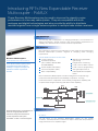
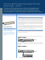
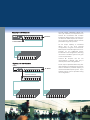
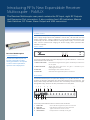
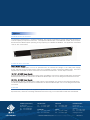
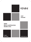
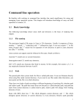
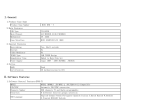
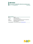
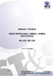
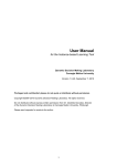
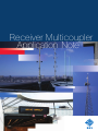
Receiver Multicoupler
Application Note
Introducing RFI’s New Expandable Receiver
Multicoupler - RxMUX
These Receiver Multicouplers may be used to improve the signal-to-noise
performance of a two-way radio system. They are compatible with both
analogue and digital technologies and also provide the ability to distribute
received signals from a single antenna system to multiple base station receivers.
The Challenge
The two-way radio marketplace is a changing landscape. The introduction of
digital technologies, shared networks, and ever-increasing expectations for
reliability have raised the bar in receiver combiner requirements.
The Solution
RFI is pleased to announce the introduction of a new range of high performance
Receiver Multicoupler products targeted at satisfying these emerging
requirements.
Receiver Multicouplers
These new pRoducTs FeaTuRe:
peRFoRMance & FuncTIonaLITY
12 Vdc operation
“Full-band” operation
These Receiver Multicouplers provide
unparalleled performance with the
flexibility to configure and expand as
individual customer requirements
demand.
(132 -174 Mhz, 380-520 Mhz
and 698-960Mhz)
In-built amplifier redundancy
Low noise amplifiers (Lna)
ease of expandability
Manual or programmable
gain setting
Integral status monitoring
Local or remote alarm outputs
Local or remote programming
auto-gain adjustment on
partial quadrature amplifier
failure
RFI’s new Receiver Multicouplers have been designed to incorporate high
performance RF specifications and reliability of operation. This high
performance level is coupled with a user-friendly configuration capability and
comprehensive integral monitoring and alarm status capability.
LEDS
GAIN
USB
CONTROLLER
ALARM
RF OUTPUTS
RFI INPUT
TTA Interface
ATTENUATION
EXPANSION PORT
DC I/P
Receiver Multicouplers should always be
linked to an appropriate Receiver
Preselector that passes the desired
receive frequencies and rejects
transmitter or other out-of-band signals.
POWER SUPPLY
Product Description
RF InpuT
The RF Input of the Receiver Multicoupler utilises an “n” female
connector. Internal protection is fitted to this input to assist with the provision of
surge protection for the amplifier stages.
RxMUX
EXP PORT
RF OUTPUTS
RF INPUT
RF INPUT
This internal surge protection supplements
the correct implementation of external surge
protection and grounding practices that
should be fitted to all receiver antenna and
feeder installations.
50 OHM TERMINATION
TTa InTeRFace
a Tower Top amplifier (TTa) Interface can be incorporated into a Receiver Multicoupler
application. This capability allows the deployment of an optional TTa with a Receiver
Multicoupler to provide the benefits of improved system uplink performance into a
network.
This capability provides a future TTa deployment capability to a receiver combiner
system utilising this Receiver Multicoupler product range.
TTA
COAXIAL
FEEDER
TTA POWER SUPPLY
RECEIVER MULTICOUPLER
Low noIse aMpLIFIeR
a quadrature Low noise amplifier (Lna) design is utilised in the Receiver Multicoupler to provide optimised performance.
The use of high 3oIp devices and design practices within the Lna ensures that high linearity and low intermodulation
susceptibility is provided across a broad dynamic range of input signal levels. This capability is particularly important
for in-building and in-tunnel systems that may experience high input levels when radio handsets can venture into close
proximity of antennas or radiating cables.
For digital technologies, this broad dynamic range capability can assist in ensuring maximum performance is provided
across the entire range of RF input levels – from the weakest signal from a distant portable, to a strong signal from a
nearby mobile. This capability can allow the full potential of low bit error rate (BeR) performance in the network’s
uplink (or “talk-in”) sensitivity to be realised.
an additional benefit of the quadrature Lna design is the inherent redundancy of the parallel amplifier stages. an autoGain feature automatically restores the set gain of the Receiver Multicoupler in the event of failure impacting one amplifier stage within the quadrature amplifier, allowing continued operation and ensuring the network remains in operation
until the fault is rectified. Integral amplifier stage status monitoring will provide an alarm Led indication and relay contact output to report the alarm state. This level of redundancy provides an inherent level of fault tolerance and network
resiliency that can be of particular benefit in operations-critical applications.
Introducing RFI’s New Expandable Receiver
Multicoupler - RxMUX
These Receiver Multicouplers may be used to improve the signal-to-noise
performance of a two-way radio system. They are compatible with both
analogue and digital technologies and also provide the ability to distribute
received signals from a single antenna system to multiple base station receivers.
aTTenuaToR
a digital step attenuator is incorporated within the Receiver Multicoupler design to
provide the capability to easily configure the gain of the network’s receiver combiner
system. This attenuator setting can be configured by manually setting the Bcd
rotary switches located on the rear of the unit or via the usB programming interface.
The programming interface can be used to configure whether the Bcd or usB gain
value is used in the attenuator, and the ability to set this preference can allow the
unit to be configured without a pc, or alternatively, to prevent on-site tampering of
the system if desired.
Receiver Multicouplers
expandaBaBILITY & FLexIBILITY
These Receiver Multicouplers can be easily
expanded in the field, catering for output
capacities of up to 128 outputs.
They provide unparalleled performance
with the flexibility to configure and expand
as individual customer requirements
demand.
The ease of changing the Receiver Multicoupler gain can also be used to
compensate for any additional losses introduced into the receiver combiner system
through the future addition of expansion Multicouplers - maintaining consistent
system performance throughout future expansion phases.
RF ouTpuTs
a multi-stage output divider is provided in the Receiver Multicoupler. eight (8)
RF outputs and one (1) expansion port are provided in the Receiver Multicoupler,
all utilising n-female connectors.
RxMUX
RxMUXConfiguration
Configurationfor
forup
upto
to88Outputs
Outputs
Rx
Rx
The expansion port can be used to expand the initial eight (8) RF outputs up to
Capacity 1 to 8 channels
RxMUX
RxMUX
EXP PORT
EXP PORT
RF OUTPUTS
RF OUTPUTS
RF INPUT
RF INPUT
RF
RFINPUT
INPUT
50
50OHM
OHMTERMINATION
TERMINATION
sixteen (16) RF outputs, all of equal net gain, through the use of an expansion
Diagram
each
aagain
+15dB
Diagramshows
shows
5Outputs
Outputs
eachwith
with
gain
of00toto
+15dB
Multicoupler.
If 5the
expansion
port
isofnot
used
it should be fitted with a 50 ohm
termination.
Capacity 1 to 16 channels
RxMUX
RxMUXConfiguration
Configurationfor
forup
upto
to16
16Outputs
Outputs
RxMUX
RxMUX
EXP PORT
EXP PORT
RF OUTPUTS
RF OUTPUTS
RF INPUT
RF INPUT
1
RF
RFINPUT
INPUT
POW
PO
Expansion
ExpansionMulticoupler
Multicoupler
RF INPUT
RF INPUT
++
RF OUT PUTS
RF OUT PUTS
8
Diagram
Diagramshows
shows14
14Outputs
Outputseach
eachwith
withaagain
gainofof00toto+15dB
+15dB
SWITCH
FAULT
POWER
POWER FAULT
+ -
NC
C
EXP PORT
USB
GAIN
EARTH
T
T
USB
Expansion Multicoupler
RECEIVER MULTICOUPLER
RF INPUT
1
RF OUT PUTS
2
3
4
8
9
10 11
EXP PORT
12
Diagram shows 14 Outputs each with a gain of 0 to +15dB
RF INPUT
EARTH
1
2
3
4
5
6
Capacity 1 to 64 Channels
For RF output capacities above sixRxMUX
teen (16)
channels, the expansion port
RFshould
INPUT
be terminated and multiple
expansion Multicouplers connected to
the Receiver Multicoupler RF outputs.
up to sixty-four (64) RF outputs can be
provided through this process.
Expansion Multicoupler
RxMUX
+ -
NC
C
EXPRF
PORT
OUTPUTS
EXP PORT
USB
RF INPUT
RF OUTPUTS
EXP PORT
RF INPUT
GAIN
EARTH
EXP PORT
50 OHM TERMINATION
8
9
10 11
12
RF OUTPUTS
as the output capacity is increased
above that of the 9-16 channel
configuration, the gain of the Receiver
Multicoupler should be adjusted to compensate for the additional losses
introduced in this configuration, restoring
the receiver combiner system’s net gain
to the required value.
RF INPUT
RF INPUT
RF
RFINPUT
INPUT
RF
RFOUT
OUTPUTS
PUTS
EARTH
RF OUTPUTS
1
2
3
4
5
6
7
8
Capacity 1 to 128 Channels
RF OUTPUTS
RF INPUT
RF INPUT
Expansion Multicoupler
RF INPUT
RF
RFINPUT
INPUT
RF OUT PUTS
RF
RFOUT
OUTPUTS
PUTS
RF INPUT
RF
RFOUT
OUTPUTS
PUTS
For RF output capacities above sixty-four
(64) channels, the expansion port can be
used to double the possible capacity of
the Receiver Multicoupler system. up to
128 RF outputs can be provided using
this configuration.
RxMUX
EXP PORT
RF OUT PUTS
unused RF outputs can be left
unterminated if desired, with only a
minimal performance degradation.
RF
RFINPUT
INPUT
T
2
7
RxMUX Configuration for up to 64 Outputs
POWER FAULT
1
RF OUT PUTS
R
Introducing RFI’s New Expandable Receiver
Multicoupler - RxMUX
The Receiver Multicoupler rear panel contains the RF Input, eight RF Outputs
and Expansion Port connectors. It also contains four LED indicators, Manual
Gain Switches, DC Power, Alarm Output and USB connectors
poweR suppLY
The Receiver Multicoupler is designed to operate from a typical +12 Vdc source.
other supply voltage options are available to suit 24 Vdc, -48 Vdc and other dc
supply requirements. Many installations of these Receiver Multicouplers may
conveniently use either the Base station’s existing power supply - or the site’s main
ups - with an optional wide ranging ac power supply mains operation also
available if required.
FRonT paneL
RxMUX
RxMUX Configuration for up to 8 Outputs
Receiver Multicouplers
EXP PORT
RF OUTPUTS
RF INPUT
RF INPUT
These Receiver Multicouplers can
be easily configured in the field,
uration
for
up
to each
8 Outputs
Diagram
shows
5 Outputs
with a gain of 0 to +15dB
allowing parameters to be adjusted
to cater for network optimisation,
expansion and re-deployments.
50 OHM TERMINATION
RxMUX Configuration for up to 16 Outputs
RxMUX
RF OUTPUTS
RF INPUT
RF OUTPUTS
RF INPUT
RF INPUT
NATION
1. Switch Control LED
2
3 LED4
3.1 Fault
5
3
4
uration for up to 16 Outputs
NC
C
1
RF INPUT
RF OUTPUTS
2
3
EARTH
4
5
1
2
6
3
4
5
6
7
EXP PORT
POWER FAULT
EXP PORT
RF INPUT
+ -
RF INPUT
NC
C
RF OUTPUTS
USB
7
8
RF OUTPUTS
RF INPUT
RF INPUT
RF INPUT
GAIN
EARTH
50 OHM TERMINATION
EXP PORT
Expansion Multicoupler
RF OUT PUTS
8
9
RF INPUT
10 11
RF OUT PUTS
12
utputs each with a gain of 0 to +15dB
These rear panel indicators and connectors are as follows:
RF
RFOUT
OUTPUTS
PUTS
3
4
RF INPUT
RF OUTPUTS
RxMUX
RF
RFINPUT
INPUT
2
EXP PORT
RxMUX Configuration for up to 64 Outputs
RxMUX
RF OUTPUTS
POWER
GAIN
RF INPUT
EXP PORT
FAULT
Green Led which lights when power is connected.
EXP PORT
USB
1
7
Red Led lights when a fault
is detected.
6
RF INPUT
Expansion Multicoupler
USB
8
9
10 11
12
The
Receiver
Multicoupler rear panel also displays four (4) Led indicators. It also
contains the RF Input, expansion port and 8 RF output ports n connectors. dc
power, alarm Relay and usB connectors are conveniently located, and the gain
setting Bcd rotary switches are also presented on the rear panel.
Diagram shows 14 Outputs each with a gain of 0 to +15dB
RF OUTPUTS
2
Yellow Led which lights when the gain is controlled by the
usB programmed value.
4. Power LED
ReaR paneL
RF OUT PUTS
1
Yellow Led which lights when the gain is controlled by the switches on
the rear panel.
2. USB Control LED
EARTH
RF INPUT
POWER
SWITCH
+ -
puts each with a gain of 0 to +15dB
FAULT
RECEIVER MULTICOUPLER
POWER FAULT
Expansion Multicoupler
USB
The
Receiver Multicoupler front panel displays four (4) Led indicators. These front
RxMUX
panel indicators are as follows;
RF INPUT
EXP PORT
SWITCH
RECEIVER MULTICOUPLER
conFIGuRaBILITY
RxMUX
1.
Power LED
2.
Fault LED
3.
USB Connector
RF
RFINPUT
INPUT
4.
Green Led which lights when power is connected.
Red Led which lights when a fault is detected.
OUTPUTS
Type B connectorRFto
connect to a pc.
RF INPUT
RF INPUT
RF
RFOUT
OUTPUTS
PUTS
Gain Switches
EARTH
on for up to 64 Outputs
RxMUX
RF OUT PUTS
Rotary switches to manually set the gain.
1
2
3
4
5
6
7
8
5.
Expansion Output
n (f) connector to connect to the optional 8 way expansion unit.
6.
RF Output
one of eight n (f) connections to the receivers.
7.
RF Input
n (f) connection to the receiver antenna via a receiver preselector.
8.
Power Connector
2 way phoenix connector to connect to the dc power supply.
9.
Alarm Connector
3 way phoenix connector to connect to external alarm devices.
10. USB Control LED
Yellow Led which lights when the gain is controlled by the switches on the rear panel.
11. Gain Control LED
Yellow Led which lights when the gain is controlled by the usB programmed value.
12. Earth Screw
Termination for connection to an equipment earth.
pRoGRaMMInG
a usB serial communications port is
provided on the Receiver Multicoupler. This
port can be used for programming, status
and alarm interrogation and firmware
upgrades.
FIRE_TOWER, RX3852-3408-31 VO.1,SERIAL No.14 _ NOV _ 2008
The communications protocol uses a
simple, text-only terminal emulation format
compatible with most common types of
computers. usB drivers are provided on a
cd with each Receiver Multicoupler unit.
12V
OK
9V
OK
USB Gain
Switch Gain
Gain Control
Current Gain
AMP-1
OK
=
=
=
=
AMP-2
OK
0dB
17dB
Switches
17dB
programmable parameters include;
site name
Gain setting
Manual or programmable Gain control
when connected to a landline or wireless modem, this usB connection can be used to facilitate remote programming
and/or monitoring of the Receiver Multicoupler.
aLaRMs
The new Receiver Multicoupler models feature integral power supply and amplifier stage status monitoring and alarm
reporting. parameter status can be interrogated via the unit’s usB port. alarm conditions are presented by Led
indicators and also by dry-voltage relay contacts, with both normally-open (n.o.) and normally-closed (n.c.) connections available for use.
The alarm conditions that are monitored and reported are;
Internal 12 Vdc supply within tolerance
Internal 9 Vdc supply within tolerance
amplifier 1 status
amplifier 2 status
Options
expansIon MuLTIcoupLeR
The expansion Multicoupler is supplied separately, and can be purchased to provide easy field-expansion of
channel capacity as required in the future. The expansion Multicoupler is a broadband module, and is compatible with Receiver Multicouplers operating on any frequency from 66 Mhz to 960 Mhz. It is supplied on a standard
1Ru 19 " rack mount panel.
poweR suppLY opTIons
Mains power supply
If the Receiver Multicoupler is not to be operated from the network dc voltage or site ups power supply,
a 100 - 240 Vac universal mains power supply unit is available to power the Receiver Multicoupler. This unit is
supplied pre-terminated for direct connection to the Receiver preselector’s 12 Vdc Input connector.
18 Vdc - 36 Vdc power supply
a fully-floating 18 Vdc - 36 Vdc power supply option is available. This option is fitted internally within the Receiver
Multicoupler and must be ordered with the Receiver Multicoupler unit. It is not designed to be field retro-fitted.
36 Vdc - 60 Vdc power supply
a fully-floating 36 Vdc - 60 Vdc power supply option is also available. This option is also fitted internally within
the Receiver Multicoupler and must be ordered with the Receiver Multicoupler unit. It is not designed to be field
retro-fitted.
shIppInG
These Receiver Multicouplers are supplied complete with a Quick start Guide, a 50 ohm termination for the
expansion port, and a cd containing usB drivers and a soft copy of the Quick start Guide and user Manual.
SYDNEY (Head Office)
po Box 4762
north Rocks nsw 2151
ph: +61 2 8838 0900
Fax: +61 2 9630 0844
rfi.com.au
MELBOURNE
ph: +61 3 9751 7500
Fax: +61 3 9761 6288
ADELAIDE
ph: +61 8 8245 1900
Fax: +61 8 8346 2244
BRISBANE
ph: +61 7 3621 9400
Fax: +61 7 3252 5505
PERTH
ph: +61 8 9311 0600
Fax: +61 8 9311 0688
INTERNATIONAL
po Box 340
Banyo QLd 4014
australia
ph: +61 7 3621 9400
Fax: +61 7 3252 5505
[email protected]
© 2010 R F Industries Pty Ltd. Data subject to change without notice.
AN-40421-1