1
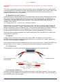
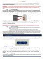
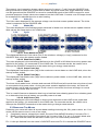
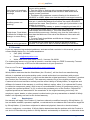
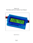
windynation ACCUMAX POWER METER MEA-DCMR-50 User’s Manual windynation Table of Contents 1 2 3 4 5 Introduction ................................................................................................................. 3 1.1 Features ..........................................................................................................3 1.2 Specifications...................................................................................................3 1.2.1 Electrical Specifications........................................................................................ 3 1.2.2 Physical Specifications ......................................................................................... 3 1.3 Safety Precautions ...........................................................................................3 Installation ................................................................................................................... 3 2.1 Maximum Current Capacity ..............................................................................4 2.2 Wiring ..............................................................................................................4 2.3 Connectors ......................................................................................................4 2.4 Powering The Meter.........................................................................................4 2.4.1 Auxiliary Power .................................................................................................... 5 2.4.2 Initial Verification .................................................................................................. 5 Operation .................................................................................................................... 5 3.1 Start-Up Screen ...............................................................................................5 3.2 Measurements .................................................................................................5 3.2.1 Amps (A) .............................................................................................................. 5 3.2.2 Volts (V) ............................................................................................................... 6 3.2.3 Watts (W) ............................................................................................................. 6 3.2.4 Cycle.................................................................................................................... 6 3.3 Resetting The Meter ........................................................................................6 Application................................................................................................................... 7 4.1 Battery Charging ..............................................................................................7 4.2 Battery Discharging..........................................................................................7 4.3 System Characterization ..................................................................................7 4.3.1 Battery Efficiency ................................................................................................. 8 4.3.2 Battery Health ...................................................................................................... 8 Troubleshooting And Support ...................................................................................... 8 5.1 Maintenance & Care ........................................................................................8 5.2 Troubleshooting ...............................................................................................8 5.3 Support ............................................................................................................9 5.4 Warranty ..........................................................................................................9 5.4.1 Restrictions .......................................................................................................... 9 5.4.2 Warranty Claims & Return Procedures ............................................................... 10 5.4.3 Disclaimer .......................................................................................................... 10 5.4.4 Limitation of Liability ........................................................................................... 11 Page 2 of 11 User Manual Revision 2 windynation 1 INTRODUCTION The AccuMax Power Meter measures current, voltage and time and from those measurements calculates peak current (Amps), peak power (Watts), minimum voltage (Volts), power (Watts), energy (Watt-hours) and charge (Amp-hours) values for you, in real-time, for the circuit in which you connect it. 1.1 FEATURES Measures energy (Wh), charge (Ah), power (W), current (A) and voltage (V) Connector to use an optional receiver battery for measurement down to 0 V Accurate & precise – 0.01 A current and 0.01 V voltage resolutions Measures peak Amps, peak Watts and voltage minimum (sag) Rugged – handles 50 A continuous and 200 A peak at 60 V 8 AWG, super fine stranded, high temperature, silicone rubber insulated wire Small & light with a tough plastic case Acts like a wire so doesn't affect performance. Precision current sensing resistor, with only 0.001 Ohms resistance and circuitry that draws only 7 mA Back-lit LCD Timer function 1.2 SPECIFICATIONS 1.2.1 Parameter Voltage Current Electrical Specifications Range Resolution 0* - 60 V 0.01 V 0 - 200 A peak 0.01 A Power 0 - 6554 W 0.1 W Charge Energy 0 - 6500 Ah 0 - 650 kWh 0.01 Ah 0.1 Wh Notes *0 V min. w/ auxiliary power. Else 4.8 V. 50 A continuous 1.2.2 Physical Specifications Parameter Value Measurement Update Period 400 mS Data Queue Sequence time 2 seconds In Circuit Resistance 0.001 Ohms Operation Current 7 mA Dimensions 2.8" L x 1.7" W x 0.83" D Weight 2.3 oz. Display Screen 16 character x 2 row LCD Nominal Operating Conditions 0° -50° C ambient temperature, non-condensing humidity 1.3 SAFETY PRECAUTIONS CAUTION: High power electrical systems pose dangers and it is the user's responsibility to be familiar with these dangers and take any necessary action to ensure safe use. Shorting a battery or connecting your Watt Meter to a battery can supply huge currents and have serious consequences including explosions, causing fire, damage to equipment, and personal injury. 2 INSTALLATION Insure all terminating connections are clean and tight to prevent arcing and overheating. There are risks associated with the potentially high currents measured by your watt meter. These include, but are not limited to, fire, burns and personal injury. The user must be familiar with the relevant methods, procedures and connection components before using or making any connections. It is suggested that any connectors and wires chosen for use be appropriately sized and rated for the intended application and attached in the manner recommended by their respective manufacturers. Revision 2 User Manual Page 3 of 11 windynation CAUTION: Poor connections and or intermittent/loose connections can cause component damage. The meter is essentially a jumper wire and provides a direct connection between corresponding colored SOURCE and LOAD wires. When powered both the “SOURCE” and “LOAD” leads of the meter are electrically “hot” when a battery is connected to either side, allowing the user to measure what the meter is connected to. 2.1 MAXIMUM CURRENT CAPACITY Current flowing through the watt meter’s wires generates heat due to the resistances of the wires and of the precision internal current shunt used for current measurements. Though very low (~ 0.004 Ohms in 8 gage wires and 0.001 Ohms in shunt), these resistances are finite and at high currents the heat generated becomes noticeable. This is because heat is created with the "square" of the current. I.E.: heating power (W) = current2 (A) × resistance (Ohms) Doubling the current increases the heat produced four times, so at 75 Amps, approximately 28 Watts of heat is produced – mostly in the Meter’s wires. The Accumax Power Meter is rated to handle a maximum of 50A at continuous duty. The Accumax Power Meter can handle currents in excess of 50A intermittently and the temperature of the Accumax Power Meter must be monitored. Never exceed an Accumax Power Meter operating temperature of 55 Celsius! The high current handing capabilities are maximized by the meter's SOURCE and LOAD wires being kept short and cool. 2.2 WIRING Always connect and disconnect power at the meter FIRST on whichever of the LOAD or SOURCE sides that has the highest electrical inductance. Long wire runs, motors, generators, etc. can have considerable inductance. Only qualified individuals should assemble any high current connections. The Red SOURCE wire goes to Positive (Plus +) battery or other device terminals and black to Negative (Minus -). 2.3 CONNECTORS The Watt Meter is supplied with 8 AWG wires terminated with 5/16” diameter lugs. The lugs can be connected directly to a battery post, to a terminal block, or to another lug as shown below. 2.4 POWERING THE METER The Meter requires a power source providing a minimum of 4.8 VDC to operate. This can come from a power source (battery or generator) on the LOAD or SOURCE side or from the auxiliary 3pin SOURCE power input connector. Page 4 of 11 User Manual Revision 2 windynation If an auxiliary power source of 4.8 VDC or more is used (e.g. small receiver battery pack), the meter operates independently of power sources on the LOAD or SOURCE leads. This allows measurements down to 0VDC. WARNING: The Red leads and the Black leads of the Watt Meter are connected to each other so either side can be electrically "hot" when a battery or other power source is connected to one side. 2.4.1 Auxiliary Power By connecting a power source of at least 4.8 VDC to the 3-pin connector on the SOURCE side, the Meter can measure down to 0 V (e.g. standard 9V battery). The 3-pin connector’s socket will accept a Futaba J type, JR or HiTec type servo plug connector. Pin 1 is Negative and pin 2 (middle pin) is Positive. Pin 1 is the pin farthest from the meter’s SOURCE wires. Pin 3, is to reset accumulated readings. See Section 3.2 for reset operation. When using Auxiliary power, you may see small measurement values when the SOURCE and LOAD leads are not connected or are shorted together (e.g. 0.01 Volts). It is normal for small “shorted lead” voltage values to be displayed in this situation and this will NOT affect the accuracy of real measurements. CAUTION: Never short leads for testing with a power source connected to either set of leads 2.4.2 Initial Verification No exposed wires or bare connectors that can short circuit prior to connecting a battery or power source. o Properly insulate any exposed areas with electrical tape or shrink tubing. LOAD wires are safely routed and any unused wires are capped with connectors. When power is applied correctly, the meter display will show the "Startup Screen" and then begin measurements. If the Startup Screen does not appear, immediately remove the power sources and refer to the troubleshooting section of this manual. 3 OPERATION 3.1 START-UP SCREEN When power is first applied to the meter SOURCE leads, a startup screen with the firmware revision number is briefly displayed, prior to measurement beginning, 3.2 MEASUREMENTS The measurement screen is displayed after the startup screen. All data values are identified by their units (e.g. Ah, Wh, Ap, Vm, Wp) and are updated every 400 mS. Amps, Volts, and Watts values are continuously displayed while all other measured values (Vm, KWh, Ap, Wp, Ah) are presented sequentially, every 2 seconds, in the "Cycle" position of the display. 3.2.1 Amps (A) The Amps value displayed is the average current flowing through the meter’s black wire over the last screen update interval. Revision 2 User Manual Page 5 of 11 windynation The meter’s circuit operation draws a slight amount of current (~7 mA) from the SOURCE side. Being hundreds of times less current than is drawn by typical loads, this slight additional current can be ignored and the SOURCE’s current be considered equal to the LOAD’s current for most practical purposes. Amps values are measured on the LOAD side. Currents over 50 Amps should be measured for reduced time due to wire heating. 3.2.2 Volts (V) The Volts value displayed is the average voltage over the last screen update interval. The Volts value is measured on the SOURCE side. 3.2.3 Watts (W) The value displayed is the average power delivered in Watts over the last screen update interval. Watt values are measured on the LOAD side. 3.2.4 Cycle 3.2.4.1 Volts Minimum (Vm) The displayed Minimum Volts value (Vm) is the minimum voltage (or “sag”) measured on the SOURCE side, since the startup screen ended. 3.2.4.2 Watt Hours (kWh) The value displayed is the total energy delivered to the LOAD in kil0-Watt-hours since power was applied to the meter. It is measured on the LOAD side. For accurate results, be careful not to interrupt the SOURCE connection to the meter during an energy measurement. 3.2.4.3 Amps Peak (Ap) The displayed Peak Amps value (Ap) is the maximum current drawn on the LOAD side, since the startup screen ended. 3.2.4.4 Watts Peak (Wp) The displayed Peak Watts value (Wp) is the maximum power drawn on the LOAD side, since the startup screen ended. 3.2.4.5 Timer The timer clock reads hours, minutes and seconds 00:00:00 and will record time only when a load is connected to the power meter. As long as power remains applied to the meter, the timer will remain frozen until a load is connected. Once a load is connected, the timer will begin to record time. The timer resets after 24 hours. This is a useful feature to determine how long a load has been drawing power from a battery pack or to determine how long a battery can provide power to a load. 3.2.4.6 Amp Hours (Ah) The value displayed is the total charge in Amp-hours delivered to the LOAD since power was applied to the meter. It is measured on the LOAD side. For accurate results, be careful not to interrupt the SOURCE connection to the meter during a charge measurement. 3.3 RESETTING THE METER Resetting your meter will clear all accumulated readings including Ah, Wh, peak current, etc. Your meter can be reset to zero in one of two ways: 1) Completely remove voltage from meter; Source's Red AND/OR Auxiliary Connector Pin 2 2) Briefly connect the Auxiliary Connector's pin 3 to zero Volts. E.g. pin 1 or meter's black wire. a) Note that the meter will be held in reset if pin 3 is continuously connected. Pin 1 is the pin farthest from the meter’s SOURCE wires and Pin 3 is nearest the SOURCE wires. Page 6 of 11 User Manual Revision 2 windynation 4 APPLICATION 4.1 BATTERY CHARGING You can monitor the voltage, current, accumulated charge and energy into a charging battery. Connect the meter as shown below. Be sure the battery is not connected before the source generator is turned on, as the meter will track the minimum voltage on the battery during the charging process. With the source on and the battery charging, the meter displays the ongoing charging electrical values. The current (A) and power (W) show the average rate of charge and the voltage indicates the current battery charging voltage. CAUTION: When charging a battery, do not operate it outside its manufacturer's specifications. Do not allow the battery voltage to exceed the maximum value specified or charge at a current that exceeds the maximum specified. 4.2 BATTERY DISCHARGING When discharging a battery pack through the meter into a load you can monitor key battery parameters like actual available charge and energy, peak and average current and battery voltage. The diversion load device you connect on the LOAD side must be capable of handling the discharge power the battery pack can provide. Example loads include, light bulbs, power resistors, and devices specifically designed to discharge a battery like some chargers in discharge mode. If the battery pack voltage at the end of discharge will be less than the minimum 4.8 V the meter requires a battery of at least 4.8 V to the 3-pin auxiliary power connection. After connecting the LOAD to the meter, connect the battery. Discharging begins when the battery is connected. When the battery is discharged, the meter display indicates the total charge (Ah) and energy (Wh) the battery delivered to the load as well as the peak Amps (Ap) and peak Watts (Wp) used and the minimum voltage on the battery during the discharging process. 4.3 SYSTEM CHARACTERIZATION It can be very difficult to find out why a component fails. The Watt Meter’s ability to capture even brief current/power peaks and voltage minimum values can help. The Peak Amps, Peaks Watts and Voltage Minimum values will be the peaks and minimum captured following the meter’s power on sequence. Be careful in adjusting test setups to not accidentally cause a peak or voltage minimum that isn't the one you are watching for. This might happen if, for example, you connect another component to the system while it is measuring. Revision 2 User Manual Page 7 of 11 windynation The meter’s Peak Amps, Peaks Watts and Voltage Minimum values are cleared whenever the meter is powered up, so remove all power sources when you need to clear them for a new measurement. 4.3.1 Battery Efficiency Battery Charging Efficiency (BCE) is the ratio of energy put in to energy removable. Charging Efficiency = Discharge Energy ÷ Charge Energy. Efficiency is never 100% due to a variety of losses involved. If the charge energy was 15 Wh and the discharge energy is 14.2 Wh the Charging Efficiency is: 14.3 ÷ 15 = 0.95 or 95% BCE depends on both the charger and the battery so it can be difficult to determine where problems are without extra batteries or chargers. 4.3.2 Battery Health Battery Health is determined by comparing the actual energy or charge capacity with the manufacturer's specifications or record the capacity value of the "new" battery and save that as a baseline. By occasionally discharging a battery pack and comparing the energy delivered to the baseline value delivered when it was first put into service, you can track that battery's health. The percentage of baseline capacity at which a battery is considered to be at the end of its life depends on battery chemistry and how it is used. A reduction in charge capacity can also be an indication of battery pack damage or imminent failure. To summarize, the percentage of baseline or initial capacity indicates a battery's health. Baseline Capacity Ratio = Current Capacity ÷ Original Capacity 5 TROUBLESHOOTING AND SUPPORT The Watt Meter is ruggedly constructed and requires minimal care. There are no adjustable or field serviceable parts inside. Opening the case will void the warranty. 5.1 MAINTENANCE & CARE Clean the meter of any dirt or debris with a moistened cloth. Do not exert too much pressure on the display as this can permanently damage it. Inspect any batteries for cracked or bulging cases and corroded terminals. 5.2 TROUBLESHOOTING Problem Don't see the Startup Screen after applying power Display screen characters are dim Display went blank Page 8 of 11 Possible Remedies 1. Make sure the LOAD side wires are not shorted. 2. Check you have a power source (battery or charger) supplying at least 4.8 V connected to the SOURCE side wires or to the Auxiliary Power Connector. 3. Check wiring Polarity. The Red wire should be connected to the positive (Red, +, etc.) side of the power source and the Black wire to the negative side. 4. Try a 9 Volt alkaline battery as the source power. 5. Make sure reset signal on pin 3 of Aux. connector is not connected to 0V. Probably due to low voltage. Check you have a power source (battery or charger) supplying at least 4.8 V connected to the SOURCE side wires or to the Auxiliary Power Connector. It is possible the LCD got too hot and stopped working. Disconnect both sides of the meter for 15 minutes, allowing the LCD to cool, and then try reconnecting. User Manual Revision 2 windynation 1. Check the connections on the LOAD side are good and have correct wiring polarity. Only have volt readings – 2. Test the meter is working with a known charged battery of no Amps, Power or other sufficient voltage connected to the SOURCE side wires and a readings simple, known good load. 3. The Meter only measures currents flowing in the direction of SOURCE to LOAD. Make sure that the setup is arranged correctly. 1. Check the 3-pin plug is inserted properly. Black (Negative, -) wire (pin 1) should be farthest from where the meter's SOURCE Auxiliary power not wires enter the case. Red (Positive, +) wire (pin 2) should be in the working middle of connector. 2. Check the Auxiliary battery or power is supplying at least 4.8 V 1. Any time the Amps value is more than the Peak Amps value the Peak Amps value will match it. The Peak Watts value is Peak Amps, Peak Watts determined the same way. Similarly, any time the Volts value is or Minimum Voltage don't less than the Minimum Volts value the Minimum Volts value will change or seem wrong match it. 2. To reset Peak Amps/Watts and Minimum Voltage, remove power to the meter. It is normal for the meter and its wiring to get warm at high Meter & wiring get warm currents. You can cool it with a small fan blowing on the wires. 5.3 SUPPORT If you are experiencing technical problems, and cannot find a solution in this manual, you can contact Windy Nation Inc. for further assistance. Call: (805) 323-6445 Email: [email protected] Write: 398 South Ash Street, Unit C, Ventura, CA 93001 For challenging issues or to just ask a question, consider using our FREE Community Forums! Consult our community of DIY'ers for fast answers to all your questions. Post on our Forums: http://www.windynation.com/community/ 5.4 WARRANTY Windy Nation warrants that the Watt Meter (the “Product”), will be free from manufacturing defects in materials and workmanship under normal authorized use consistent with product instructions for a period of one (1) year from the date the original purchaser (“Customer”) receives the Product (the “Warranty Period”). This warranty extends only to the original purchaser. The Customer’s sole and exclusive remedy and the entire liability of Windy Nation, its suppliers and affiliates for breach of the warranty is, at Windy Nation’s option, either (i) to replace the Product (or defective component part(s)) with a new or reconditioned Product (or component part(s)); (ii) to repair the reported problem; or (iii) to refund the purchase price of the Product. Repaired or replaced products are warranted for the remainder of the original warranty period only. No employee, agent, dealer or other person is authorized to give any warranties on behalf of Windy Nation not expressly set forth in this limited warranty. 5.4.1 Restrictions No warranty will apply if the Product (i) has been altered or modified except by Windy Nation; (ii) has not been installed, operated, repaired, or maintained in accordance with instructions supplied by Windy Nation; (iii) has been subjected to abnormal physical, thermal or electrical stress, misuse, negligence, or accident. If Windy Nation determines that the problem with the Product is not due to a manufacturing defect in Windy Nation’s workmanship or materials, or otherwise does Revision 2 User Manual Page 9 of 11 windynation not qualify for warranty repair, then the Customer will be responsible for the costs of all necessary repairs and expenses incurred by Windy Nation. 5.4.2 Warranty Claims & Return Procedures To be eligible for service under this warranty, the Customer must submit a service request within the Warranty Period by contacting Windy Nation in writing or via telephone and obtaining a Returned Materials Authorization (“RMA”) number. This RMA must be obtained before returning any product under this warranty. Notification must include a description of the alleged defect, the manner in which the Product was used, the serial number, and the original purchase date in addition to the name, address, and telephone number of the Customer. Within five (5) business days of the date of notification, Windy Nation will provide the Customer with an RMA number and the location to which the Customer must return the defective Product. Any Product returned for warranty service shall be shipped at the expense and risk of the Customer. The Customer must return the entire Product kit (or, if authorized by Windy Nation, the defective component parts), within fifteen (15) days after issuance of the RMA number. Windy Nation will be under no obligation to accept any returned Product that does not have a valid RMA number. Customer’s failure to return the Product within fifteen (15) days of its receipt of an RMA number may result in cancellation of the RMA. All parts that Windy Nation replaces shall become Windy Nation’s property on the date Windy Nation ships the repaired Product or part back to the Customer. Windy Nation will use all reasonable efforts within thirty (30) days of receipt of the defective Product to repair or replace such Product. If a warranty claim is invalid for any reason, the Customer will be charged at Windy Nation’s then-current rates for services performed and will be charged for all necessary repairs and expense incurred by Windy Nation. If Windy Nation determines that a warranty claim is valid, it will ship the repaired or replaced Product to Customer at Windy Nation’s cost. 5.4.3 Disclaimer EXCEPT FOR THE EXPRESS LIMITED WARRANTY SET FORTH IN THE PREVIOUS PARAGRAPH, WINDY NATION DISCLAIMS ALL WARRANTIES, EXPRESS, IMPLIED AND STATUTORY INCLUDING, WITHOUT LIMITATION, THE IMPLIED WARRANTIES OF MERCHANTABILITY AND FITNESS FOR A PARTICULAR PURPOSE WITH RESPECT TO ANY PRODUCTS PROVIDED BY WINDY NATION. NO ORAL OR WRITTEN INFORMATION OR ADVICE GIVEN BY WINDY NATION, ITS DEALERS, DISTRIBUTORS, AGENTS OR EMPLOYEES SHALL IN ANY WAY INCREASE THE SCOPE OF THIS WARRANTY. WINDY NATION DOES NOT WARRANT THAT THE QUALITY OR PERFORMANCE OF THE PRODUCTS WILL MEET YOUR REQUIREMENTS OR THAT YOU WILL BE ABLE TO ACHIEVE ANY PARTICULAR RESULTS FROM USE OR MODIFICATION OF THE PRODUCTS. Some jurisdictions do not allow the limitation or exclusion of implied warranties or how long an implied warranty may last, so the above limitations may not apply to you. In any such jurisdiction, the warranty shall be limited to the minimum warranty and period required by law. WINDY NATION EXPRESSLY DISCLAIMS ALL LIABILITY FOR BODILY INJURIES OR DEATH THAT MAY OCCUR, DIRECTLY OR INDIRECTLY, BY USE OF THE PRODUCT BY ANY PERSON. Page 10 of 11 User Manual Revision 2 windynation 5.4.4 Limitation of Liability UNDER NO CIRCUMSTANCES WILL WINDY NATION OR ITS AFFILIATES OR SUPPLIERS BE LIABLE OR RESPONSIBLE FOR ANY LOSS OF USE, INTERRUPTION OF BUSINESS, LOST PROFITS, LOST DATA, OR INDIRECT, SPECIAL, INCIDENTAL, OR CONSEQUENTIAL DAMAGES OF ANY KIND REGARDLESS OF THE FORM OF ACTION, WHETHER IN CONTRACT, TORT (INCLUDING NEGLIGENCE), STRICT LIABILITY OR OTHERWISE, EVEN IF WINDY NATION OR ITS AFFILIATE OR SUPPLIER HAS BEEN ADVISED OF THE POSSIBILITY OF SUCH DAMAGE. Some states do not allow the exclusion or limitation of incidental or consequential damages, so these limitations may not apply to you. Neither Windy Nation nor its affiliates or suppliers will be held liable or responsible for any damage or loss to any items or products connected to, powered by or otherwise attached to the Product. The total cumulative liability to Customer, from all causes of action and all theories of liability, will be limited to and will not exceed the purchase price of the Product paid by Customer. This warranty gives the Customer specific legal rights and the Customer may also have other legal rights that vary from state to state. Revision 2 User Manual Page 11 of 11