1
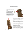
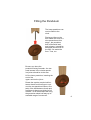
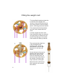
Clock 12 Owners Booklet Bruce Aitken This user manual accompanies one of the ‘Clock 12’ series of clocks designed and made by Bruce Aitken. Written and published by Bruce Aitken, Old Tram Depot Studio, 25 Rutland Street, Matlock DE4 3GN. 01629 580622 [email protected] http//www.bruceaitken-clockmaker.co.uk Copyright © Bruce Aitken 2013 All rights reserved. No part of this booklet my be reproduced in any form or by any electronic or mechanical means including information storage and retrieval systems without written permission from the publisher. 4th Edition Printed by Bruce Aitken 1 Contents Page 3 Preliminaries Page 4 A Suitable Location for the Clock Page 5 Unpacking the Clock Page 6 Drilling the Mounting Hole Page 7 Mounting the Clock Page 8 Fitting the Pendulum Pages 9 - 10 Fitting the weight cord Pages 11 - 12 Hanging The Weights Pages 13 - 14 Adjusting The Clock Page 15 Timekeeping Page 16 Running Page 17 Dismantling the and Re-packing the Clock Pages 18 - 19 Identifying the Clock Parts 2 Preliminaries Before starting to unpack and install the clock, please gather the following items: A pillow A crosshead screwdriver An decent electric drill and drill bits suitable for drilling into the type of wall the clock will be fixed to (see below and page 5). The wearing of baggy sweaters and sleeves is strongly discouraged during the fitting of the clock - the delicate wheels have been known to snag on such garments; causing damage, trauma and the need for repairs. 3 A Suitable Location for the Clock The clock can be successfully located in many settings, however a few simple precautions need to be taken: The clock protrudes from the wall by nearly 200mm (8 inches) and is delicate. It must be placed so as to exclude the chance of someone accidentally brushing against it. Alcoves are nice. The clock needs clear space beneath it for the weight to descend. The clock measures 1.3m (4’ 3”) from the very top to the bottom of the large weight at its lowest. The hands sweep through a diameter of 300mm (12”) The wall it is mounted on does need to be vertical. If your wall is wonky the clock can be modified to suit - we will have discussed this before your purchase. You may find upon installation that your chosen wall is less vertical than you had thought - if so please contact me so I can provide you with a mounting kit tailored to your needs. The clock is susceptible to temperature changes (gradual changes affect timekeeping a little; frequent, sudden and extreme swings in temperature can damage the clock). For this reason the clock should be placed away from radiators. If the clock can be kept in environment with a broadly even temperature, so much the better. Excess moisture is to be avoided - the clock should not be located in a bathroom or a kitchen. The clock does, of course, make a noise. It has a pleasant slow tick - tock that many find relaxing. Some people find that they cannot easily sleep in a room with a ticking clock, others enjoy the sound. If you enjoy listening seriously to music in your home, you may wish to keep the clock apart from the Hi-Fi. 4 Unpacking the Clock Your clock has been delivered in a cardboard box containing three layers of rigid foam. Upon opening the box you found this instruction manual on the top layer. Under this layer is the lower pendulum, the cleaning brush, the cord and mounting hardware. Once these items are removed, lift the middle layer to reveal the clock movement and weights. Before removing the clock from the packaging, locate the mounting peg and hardware and follow the instructions for fixing the peg to the wall. Mounting Peg The clock hangs from a single screw which must be firmly fixed into the wall. The mounting hole should drilled at or a little below eye level. Hopefully we have already discussed the nature of the wall that you intend to mount the clock on, an appropriate set of fixing hardware is included. Please ensure that you do not over tighten the screw or the peg may split - it only needs to be tight enough to prevent rotation. 5 Drilling the Mounting Hole Brick or Stone walls Please satisfy yourself that the wall is sound. A well secured 50mm x 4mm (2” x 8) screw will hold the clock admirably in walls of this nature. Use a 6mm masonry drill bit to drill the hole in the wall to a depth of 55mm (a length of masking tape wrapped round the drill bit will give you the right depth). Be aware of how well the drill goes in - the plaster layer is drilled very easily and the drill can wander before it meets the brick below. It should encounter reassuring resistance when it reaches the brick - if not you may have found a mortar join which could be quite weak. It also is possible that the wall has deteriorated; in either case it is not wise to hang the clock here. If the wall proves to be sound, tap the brown plastic wall plug fully into place, slip the woodscrew through the wooden mounting peg and screw it to the wall, making sure it can't be rotated. Stud walls (plasterboard over a wooden frame) Try to locate one of the vertical wooden ‘studs’ by tapping on the wall. Fixing the clock to a stud is straightforward if you find a well positioned one. Drill a hole with a 2.5mm twist drill bit, and use the woodscrew to hold the mounting cone securely to the wall. If you are unable to find a suitable stud, you will need to use the cavity wall fixing. You have been provided with an M3 x 50mm toggle fixing which you will have to unscrew, slide the mounting peg onto and reassemble. A 10mm drill bit will be needed to make the hole in the plaster board. Lath and plaster walls Walls of this type are old and may well be weak. If you are confident in yours use the M3 x 50mm toggle fixing as above, but do take care to ensure that the arms open vertically so they can grip the horizontal laths well. 6 Mounting the Clock While handling the clock please avoid touching the wheels at all times. The clock is best held by the upper part of the frame front and the top of the wall bracket. Notice the keyhole shaped slot in the rear of the back plate - the lower (circular) part of this slot will engage with the mounting peg on the wall. When the clock is sitting on the mounting peg ensure that the frame back plate is right up against the wall, then apply even firm pressure downwards. The frame should shift downwards with a satisfying ‘clunk’, indicating that the clock is correctly mounted on its peg. It may prove difficult to press the clock into place - in this case it should be lifted and put to one side momentarily. The peg will need to be unscrewed, and the optional plywood spacer should be employed. This is further complicated if a cavity wall toggle fixing has been used. In this case unscrewing the peg will cause the toggle part to be lost in the wall - this is why you have been given two. 7 Fitting the Pendulum The lower pendulum can now be fitted to the clock. Placing a pillow on the floor under the clock is a wise precaution at this stage - the pendulum bob is filled with lead and is heavy; it would be damaged should it fall to the floor. So would the floor. Toes, too. Be sure you have the pendulum facing forwards - the two small screws in the circular pendulum joiner should be to the rear. Lift the lower pendulum, inserting the end of the upper rod into the joiner. Rotate the captive wooden ball between thumb and forefinger to connect the two pendulum halves. One twist of the ball between thumb and forefinger is about one third of a full rotation - 30 of these twists will bring the pendulum about half way up its available range of movement. 8 Fitting the weight cord This simplified illustration shows the a close-up of the weight cord (shown in mauve) fitted around the two pulleys and the central winding arbour, with the great wheel behind. The sequence that follows shows how the cord is laced within the clock. In these images the lower clock frame has been shown as a translucent grey block to indicate the sections of cord that go in front of the frame and those which go behind. 1 The cord terminals (light blue in the illustrations) are marked L & R - first fit the one marked R into the right hand hole in the frame as shown. On the left side of the clock in between the frame and the great wheel, loop the cord over the left hand pulley. Allow most of the cord to fall to the outside, forming a long loop as shown on the right. Notice how the cord lines up with a groove in the central drive arbour. 9 2 3 Notice also that there are small metal pins sticking up out of the bottom of this groove - these hold onto the cord and stop it the slipping through the groove. Wrap the cord up underneath the winding arbour, then over the top of the angled pulley and down in front of the frame. Bring the cord back up and insert the other terminal (marked L) in its hole. Before hanging the weights in their loops, make certain that the cord is snugly seated in the arbour groove by pulling gently on the sections marked A & B simultaneously. Now check that the cord runs evenly and remains in the groove by pulling B down while letting A up gradually. The loops should hang evenly, as shown in the illustration on the right. B A 10 Hanging The Weights The weight cord will probably require some adjustment to persuade it to hang evenly. This is accomplished by rotating the corresponding cord terminal until any twists have been unwound. This needs to be done to avoid a perilous situation - small twists in the cord can gradually work their way round to the winding arbour and eventually cause the cord to ride up out of its groove. The cord can then slip completely out of the groove, allowing the weight to fall rapidly: potentially damaging the clock, the weight and anything it lands on. 11 Before hanging the weights, please double check to ensure that the cord is well seated in its groove in the drive arbour. Sorry to keep going on about it. Slip a thumb into the nearer of the two loops in the cord and apply a little downward pressure as you hang the large drive weight in the other loop. Now hang the counterweight in the nearer loop. The clock is wound by placing a thumb in the counterweight hole and pulling downwards, lifting the drive weight. A good deal of force is required to raise the weight; expect the ratchet mechanism to make a moderately loud noise during winding. 12 Adjusting The Clock The clock must now be adjusted to bring it “in beat”. Simply put, this means that the clock escapement should be running evenly. The escapement is the name given to the two uppermost moving parts of the clock - the very top part (which rocks back and forth) is called the anchor; the wheel directly beneath is the escape wheel. The anchor has two pallets, these are the parts which make contact with the escape wheel. Your clock features a new design of escape anchor which is much simpler to adjust than earlier versions. Once you are happy that the clock looks vertical, gently move the pendulum as far as possible in the direction shown. The tip of the left pallet will touch the ‘land’ between two escape teeth (shown opposite, top) 13 The pallet touches the bottom land between two escape teeth, as expected Now release the pendulum, which will swing in a wide arc. During the first few swings the escapement ‘self adjusts’; the pendulum will swing less energetically over the next few minutes as it reaches its normal running amplitude. The clock may sometimes shift out of adjustment, possibly while winding or if it happens to run down and stop. If so, check it’s still vertical then repeat the process of gently taking the pendulum to its maximum extent before releasing. This re-adjustment is the first step if the clock should ever stop working. 14 Timekeeping To adjust the clock hands First grasp the adjuster and press it towards the clock (this disengages the hands from the main movement). Rotate the adjuster clockwise while continuing to press - the hands follow. Set the time. The clock is capable of keeping time accurately. If the clock is running slow rotate the adjusting ball as shown in the left hand illustration, follow the right hand illustration if it is running fast. The table shows how many turns of the ball are needed. daily If the Clock Runs Slow 15 difference adjustment (in minutes) (ball turns) 4 2 1 24 12 6 weekly difference adjustment (in minutes) (ball turns) 4 2 1 4 2 1 If the Clock Runs Fast Running The clock is designed to be wound at roughly the same time each day - it will run for around 30 hours on one complete wind. Apply a firm even downwards force, but try not to rush the winding - aim to have wound the clock by the time you have counted to three. Allow the drive weight to meet the bottom of the clock frame gently as you complete the winding. The clock will run backwards during the winding - the time keeping is thus affected, but not by very much. My later clocks will include a ‘maintaining power’ arrangement, when I’ve worked out how to do it. It is possible that the clock will stop in the few minutes after winding it - if so, simply restart it. If the clock is allowed to run down it will stop, the counterweight resting against the bottom of the frame. Wind the clock again, and gently restart. Your clock has been supplied with a soft brush for dusting - this can be done while the clock is running. Gentle strokes away from the centre of each wheel does the trick. The normal running of the clock can be disrupted by a few circumstances. Should it become reluctant to work try these procedures: Restart the clock - if it runs, check that it is running ‘in beat’ (the escapement anchor swings away from the escape wheel by the same amount on each side). This adjustment can drift over time re-adjust if needed. If the clock won’t start (the escape wheel doesn’t rotate at all when the pendulum is swung) several steps can be taken - first take the escape wheel and gently jiggle it in and out, and repeat for the intermediate wheel. Now rotate the clock hands a full 12 hours before setting the time and re-starting the clock. Normally these methods will encourage the clock to return to its normal stable running. If it continues to require frequent re-starts, however, it may need to be returned to the workshop. Please do not hesitate to get in touch if you experience any difficulty with the clock. 16 Dismantling the and Re-packing the Clock At some time it will be necessary to dismantle the clock for storage, moving house or returning to the workshop for maintenance. You will need the original packing Wind the clock so that the main weight is above half way, as shown. Set the time to read 12:00 (1). Stop the clock by gently arresting the pendulum bob (2). Remove the counterweight (3) followed by the drive weight (4). Remove the cord terminals from the frame (5). Slip the cord off the left hand pulley first, allow it to drop under the clock, then lift it from the right hand pulley (6). If the clock is being returned to the workshop, our discussion will have clarified which items need to be included - probably just the clock mechanism. If this is the case, the weights will need to be stored safely outside the crate. If the entire clock is being packed, put the weights in their places now, wind up the cord and bag it. Place the pillow on the floor under the clock and dismantle the pendulum by rotating the adjusting ball until the lower pendulum comes free. This might not need to be returned to the workshop either. The clock can now be lifted from its peg - it may well be hard to remove. First grip the back plate and ease it from side to side. Place one hand over the top of the clock, gripping the bracket sides, and push the back plate upwards with the other hand. A gentle side to side rocking motion will free the clock, whereupon it can be lifted free of the mounting peg. The clock can now be placed in position in the packaging. Please ensure that the clock is only handled by the back plate and bracket. 17 If the clock is to be stored, please be aware of its environment. It can withstand wide temperature variations but storage at an even cool room temperature is preferred. The clock does not like frequent, rapid changes in temperature. Please ensure that it is stored in a dry place, especially for long term storage. Identifying the Clock Parts Pendulum Joiner Clock Mechanism Lower Pendulum Rod Bob Drive Weight Counterweight 18 Identifying the Clock Parts (continued) Pendulum Mount Frame Front Wall Bracket Side Frame Center Frame Back Plate Escapement Crutch Escape Wheel Intermediate Wheel Second Wheel First Wheel Hand Adjuster Great Wheel Upper Pendulum Rod Third Wheel Motion Work Going Train Pulley Anchor Drive Pins Pallets Drive Arbour Escape Wheel Ratchet Wheel Cord Terminal Ratchet Pawl 19