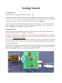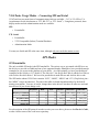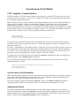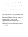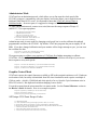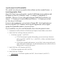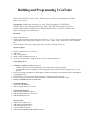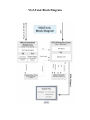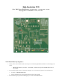
1
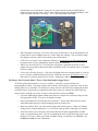
User Guide and Reference Manual
Getting Started
Providing Power
VGATonic needs to be provided with 5V in order to work.
Connect VGATonic's USB Type B port to an open USB port on the device which will be using the
VGATonic video card. (If there are no USB ports available or you would prefer to power VGATonic
in another way, please see the power labels on the PCB picture in the Appendix.)
Note that if you don't power VGATonic from the board you will be using to drive it, you should also
connect a jumper between ground on the driver and ground on VGATonic to have a good reference.
See the Appendix for grounding points onboard VGATonic.
Connecting VGA
Once power is provided to the board, connect a VGA cable between VGATonic's VGA port and a
VGA port on your monitor, TV, converter, or other device.
Be careful you do not connect VGATonic to a device which provides VGA output – you can destroy
VGATonic or the other device! Double check you are only connecting VGATonic to an output device
or a converter which accepts VGA input.
If all is connected and your device didn't already autodetect VGATonic, switch your device on and set
the device's input to VGA. You may need to read the user manual for instructions on how to do that
for your unique situation.
VGATonic starts up with an all green screen; if your device is connected to VGATonic and displays a
green screen – congratulations, VGATonic is powered up and working! You are now ready to pick a
mode and start using VGATonic as a framebuffer or terminal emulator!
VGATonic Usage Modes – Connecting SPI and Serial
VGATonic has two main forms of communication which are available – 5v/3.3v/2.5v SPI or 3.3v
Asynchronous Serial (also known as “TTL RS-232” or “TTL Serial”). Using those protocols, three
display modes and one administration mode are available:
SPI:
•
Framebuffer
TTL Serial:
•
Framebuffer
•
VT52 Compatible (Subset) Terminal Emulator
•
Administration Mode
You may use Serial and SPI at the same time, although only one can be the master at once.
SPI Modes
SPI Framebuffer
The only available SPI mode is the SPI framebuffer. The easiest way to get started with SPI is to use
the drivers we provide on Github and one of our supported boards, although we have provided enough
examples for you to port to the platform of your choice. As of this printing, we have provided driver
examples for the Raspberry Pi 2 Model B, The Odroid C1, the BeagleBone Black, and the Intel Edison
with Arduino Breakout Board. We have also provided user mode drivers and Arduino driver code.
The SPI header onboard VGATonic contains “SCK”, “MOSI”, “MISO” and “CS” (Chip Select) pins but “MISO” can go unconnected. The pins in the table are board dependent and go by the board's
naming conventions. You can, of course, change these in the drivers, but these are what we used and
must be used if you do not change code:
Chip Select
MOSI
SCK
CS Label
MOSI Label
SCK Label
Raspberry Pi 2 Model B
22
19
23
BCM 25
BCM 10 (MOSI)
BCM 11 (SCLK)
Odroid C1
22
19
23
#103
#107
#105
BeagleBone Black
15
18
22
GPIO_48
SPIO_D1
SPIO_SCLK
Intel Edison
8
11
13
49
43/SPI_2_TXD
40/SPI_2_CLK
Arduino Uno
9
11
13
9
11
13
For a description of the SPI protocol in order to write your own driver, please see the Hacker's Guide,
or take a look at some of the code in our repository.
Asynchronous Serial Modes
VT52 Compatible Terminal Emulator
VGATonic includes a VT52-like terminal emulator, which provides a subset of VT52 escape codes as well as
VGATonic specific (and unique – do not try on a working VT52) escape codes and administrator escape codes.
It also includes a single font in memory.
When VGATonic starts up, it quickly initializes the oscillator and prints a green screen, and puts the SPI bus in
charge of the VGA Output. In order to use the terminal emulator, you must connect over serial and put the
terminal emulator in charge. Connect over TTL Serial at 9600 baud 8-N-1 (please see your serial device's
manual for information on how to connect; it is beyond the scope of this document. On a Macbook, I use a USB
to Serial Adapter and the 'screen' program in a terminal to connect.) The TX and RX pins onboard VGATonic
should be used to connect to serial – ensure you properly connect your serial device.
Escape m # (Master mode)
Escape s # (Select CPLD)
Escape Z r # (Set to 8 bit color depth at 160x120 resolution, since we don't know what we were in.)
To ensure the serial connection now has control of the display driver, you can now send ASCII characters to
VGATonic and see if they are printed on your screen. 'Escape E' (capital 'E') clears the screen and moves the
cursor to the upper left.
If it works – congratulations! The terminal emulator is simply the easiest way to add VGA output to a project, as
the serial protocol is widely supported at 9600 baud. Any microcontroller or TTL serial output that supports 8N-1 serial at 3.3 volts can communicate with VGATonic and display characters and colors on the screen. It is
particularly useful as a debugging output window for projects with serial available.
A complete copy of all codes supported can be found in the Appendix. Information on how to use high-speed
38400 baud mode is in the Administration section below.
To give control of the display driver back to the SPI connection, either power cycle VGATonic or use this
command sequence over serial:
Escape Z r 0 (Set to 8 bit color depth at 640x480 resolution, since we don't know what we were in.)
Escape u # (Unselect CPLD)
Escape r # (Release master mode)
Asynchronous Serial Framebuffer
While using the terminal emulator, VGATonic has special escape codes which allow you to directly write pixels
to the screen. While 640x480x8bpp will be painfully slow even at 38400 baud, with modest resolutions like
80x60x1bpp you can get a usable framebuffer even over serial!
The escape characters needed are printed in the Appendix. Please see the Hacker's Guide and the python
example provided on Github for a description of how to write directly to the framebuffer over serial.
Administration Mode
The terminal emulator also has an administration mode which allow custom settings for your VGATonic. A
listing of all codes can be found in the Appendix; provisions are included for toggling the serial speed between
9600 and 38400 baud, as well as adjusting the PLL on the programmable clock in order to better sync to your
monitor. (Please see the Troubleshooting Guide for more on calibration.)
Troubleshooting Guide
Sometimes things don't work as expected! Here is a list of common problems, and
things to check in order to attempt to fix them.
VGATonic Won't Power On!
If USB is connected properly, connect another device to the USB port you are using in order to check if
power is coming from the USB port. Alternatively, VGATonic can be powered through other pins on
board – see the Appendix for details. When not using USB: always connect ground first, only use +5V
pins to provide power, and only use one power source at a time!
VGATonic Won't Display Over VGA!
First check VGATonic is powered, then try a different VGA cable. Also, check your monitor settings to
ensure your monitor is set to VGA input on the port VGATonic is connected to.
Most if not all monitors which adhere to the VGA standard or VESA modes will sync to VGATonic, but
we are unable to test every individual device to ensure perfect compatibility. It's possible the PLL is set
incorrectly too; see the section on resetting the PLL to factory below if you think this is the case (usually
the monitor will have a notice or indication it cannot sync). Analog monitors will likely provide the best
user experience, if available.
My Monitor Won't Sync to the VGATonic Signal!
From factory, VGATonic is .0119% out of spec from the VGA clock; a standard monitor will only have
issues with between 0 and 49 displayed pixels, total, in our top mode. If you think you have changed the
clock setting inappropriately in Administrator Mode, you can reset the PLL to factory easily. Power
cycle, connect over serial at 9600 baud 8-N-1 and issue the following commands:
Escape % & # to reset the LTC Calibration bit to factory
Escape % | # to burn the factory bit to EEPROM
My Serial Connection Isn't Working!
VGATonic starts in 9600 baud 8-N-1 mode, but can be changed to 38400 mode. Try using the speed
you aren't currently connecting at; if that doesn't work, power cycle VGATonic and connect at 9600
baud 8-N-1. Be sure you are using 3.3V serial – RS-232 voltages can destroy VGATonic!
VGATonic Won't Respond to SPI or Serial Writes!
First, ensure the bus you want is the master of the Display Core. After a power cycle, SPI will be in
charge – see the section on the VT52 Compatible Framebuffer for information on how to change it.
VGATonic is Working but My Colors Are Suddenly Inverted/Don't Match What is Expected!
If VGATonic was previously working, the most common cause of this is poor signal integrity – the chip
select line is particularly sensitive to interference. The easiest way to clean it up is to twist 5v power or
ground supplies around sensitive signals. You may need to power cycle.
SPI Won't Respond/SPI is Causing Garbled Output!
There are many things to check here, so this is not a complete list:
•
How fast is SPI Running? VGATonic is in spec up to 59.7 MHz SPI, although we have tested at
up to 62.5 MHz successfully.
•
How is Your Signal Integrity? At faster speeds, long wires become antennas. Ensure your wires
are as short as possible, with strong and firm connections to both your device and VGATonic. It
usually helps to use twisted pairs; wrap power or ground signals around your SPI signals to
cancel out some coupling issues. Here is some example routing with a BeagleBone Black. Note
USB is not used for power in the image... if it is, only add ground connections:
•
Which SPI Mode is Running? VGATonic works 'best' in SPI mode 3 or 0 on most hardware, but
because SPI is a loose standard, please try 1 and 2 if that isn't working. (You will need to make
this change in software, which is beyond the scope of this booklet.)
•
Is SPI Correctly Output? Due to hardware differences, we can't test every SPI implementation –
but please ensure you are getting SPI as expected from your hardware.
•
What's Your Ground Reference? If VGATonic is physically separated from its driver, run a
jumper between ground (as short and/or thick as possible) on the two modules to have a common
reference voltage.
•
Is Chip Select Working Properly? Chip select is fraught with issues on many boards; it is easiest
to use a software controlled chip select because VGATonic does up to 307,200 byte writes. For
that reason, use software chip select for control. Additionally, double check CS signal integrity.
My Picture Isn't Perfectly Stable! There is Pixel Drift and/or Jagged Lines!
VGATonic prioritized hackability over perfect stability - eschewing a crystal oscillator for a
programmable oscillator. That opens up more future features, but you may see minor dot crawl or other
analog artifacts on your monitor. We also drove to keep costs low, and VGATonic managed to arbitrate
reads and writes in single buffering onboard instead of more expensive schemes like double buffering.
Anyway, there are things you can try in order to clean up before you beg for HDMI:
•
Lower bit depths toggle outputs multiple time based on a single write, while more bits per color
will toggle more slowly. If you can, use higher bit depths.
•
Noise on the MOSI line can make the screen look 'torn'. Noise on the chip select line, on the
other hand, might show up as rapidly changing modes or partial writes.
•
Most new monitors allow you to fine tune for phase and clock frequency – check your monitor
settings and try to adjust both sliders. Let VGATonic warm up before calibrating your monitor.
•
VGATonic allows you to adjust the value of the onboard LTC6903 programmable oscillator
easily over asynchronous serial. You can try adjusting the clock up and down and see how your
monitor or TV reacts. When you find an acceptable setting, you can burn it to EEPROM. See
the Hacker's Guide for more information.
Hacker's Guide
VGATonic was initially developed for Hackaday's 2014 and 2015 Prize Competitions – so a key philosophy in
the design is hackability and openness. This led me to add fun features like a programmable oscillator and easyto-program silicon like a microcontroller and a CPLD to the mix, along with (unpopulated) prototyping pins and
space to add switches.
When all was said and done, VGATonic ended up with four main components – the CPLD, the Microcontroller,
the Programmable Clock, and a 4 Mbit SRAM to hold our display data. The firmware to the CPLD and the
Microcontroller are open source, and I've included examples of protocols and framebuffer drivers in Linux for
the SPI and the Asynchronous Serial framebuffers. Of course, the VT52-like Terminal Emulator is also
available – surely there have been more than a few games written in the past which used only ASCII!
Regardless, this section houses details which a general user doesn't need to know to enjoy VGATonic – but
power users and folks who love to tweak and push the limits will find this information... enlightening!
SPI on VGATonic
SPI is the highest speed interface available to VGATonic, and you will get the best
framerates and highest quality output targeting SPI. It has no minimum speed, and the
highest recommended speed is 59.7 MHz. Faster speeds should work, but they violate
the setup time of the CPLD's buffers – so you might have issues past 60 MHz. As
always, keep connections short and clean while minimizing interference, and if you see
signal integrity issues try twisting wires and shielding your sensitive signals
(especially chip select) with 5v power or ground jumpers.
SPI Control Characters
For the SPI Framebuffer, there are two main ways to manipulate VGATonic.
1. The 'Chip Select' Signal
◦ Chip Select will reset the pixel counter to 0,0 (the upper left) to allow a new screen write.
◦ If a 'single' pixel is written, VGATonic will treat that pixel as a control character.
2. Control Characters
◦ One type of control character allows you to change VGATonic's mode.
◦ Another type controls cursor positioning, allowing hardware acceleration.
Control characters work like this:
SPI Chip Select Starts High, then
SPI Chip Select Low
Send exactly one byte of data (this is the 'control' character)
SPI Chip Select High
You can send as many control characters as you want, but only the last sent character to VGATonic
will determine behavior. VGATonic does not send any sort of acknowledgement, other than, perhaps,
changing the addressing on the screen – you should see mode changes immediately.
Control Character Type I: Changing Bit Depth and Resolution
Writing control characters that start with '0' in the MSB will allow you to change resolutions and bit
depths of VGATonic.
Our resolution modes differ from software resolutions or 'virtual' resolutions. To the monitor or
display itself, VGATonic will always present timing of 640x480 @ 60 Hz – so you don't have to worry
about compatibility issues with lower resolutions as long as 640x480 works! VGATonic does this
internally – it controls how long to 'wait' on a pixel, so the driver tells it how many bytes to expect by
setting the mode. Every drop in resolution is a halving of both width and height, so FPS potential will
be 4x as much for each reduction (up to our maximum of 60 frames per second due to VGA timing).
Our bit depth modes are similar. While on many video cards you would have to write, say, 16 or 24 1s
to signal 'white' in Black and White mode, VGATonic will internally convert between color palettes...
so a single byte sent might mean 1 (8 bit), 2 (4 bit), 4 (2 bit), or 8 (1 bit B&W) actual pixels written! In
essence, every 'drop' in color depth doubles the frame speed potential. For example: a 25 MHz SPI
part can do about 10 frames per second in 640x480x8bpp, but 20 frames per second at 640x480x4bpp.
Control bits for changing bit depth and resolution work like this (where location '7' is the MSB and '0'
is the LSB, or last bit sent in the byte). Bits 6, 5, and 4 are ignored – write whatever you like.
Bits 3 and 2: Bits Per Pixel/Color Depth
•
00 – 8 Bits Color Per Pixel (256 Colors)
•
01 – 4 Bits Color Per Pixel (16 Colors)
•
10 – 2 Bits Color Per Pixel (2 Grays, Black, White)
•
11 – 1 Bit Color Per Pixel (Black and White)
Bits 1 and 0:
•
00 – 640x480
•
01 – 320x240
•
10 – 160x120
•
11 – 80x60
You can, of course, change both at the same time:
b00000110 : tells VGATonic to set 4 bits per pixel color at 160x120 resolution.
Note that control pixels are wonky on single board computers or things without cycle accurate timing –
if they are blocked from an SPI write (for example, during a video or game where the CPU is too busy
to service another SPI write) – you may need to send more than one mode change to get it through.
Setting the mode multiple times (even if all are successful) won't hurt VGATonic. This is part
dependent and beyond the scope of this document, but if you don't see responses from a single board
computer this is the first place to check.
Control Character Type II: Hardware Acceleration
VGATonic allows for hardware acceleration – it can skip to certain rows to begin writing new pixels.
Writing a single pixel with a '1' in the MSB will cause the remaining bits to become the MSBs of the
address bits of the next pixels written. Note that each resolution and bit depth reduces the number of
addresses that are used:
•
A control byte of '11110011' would use bits '1110011' in the address MSB (dropping the first
'1'). There is an implied '00' added onto the end as the addresses themselves are 10 bits.
•
For 640x480, a control character of 11100000 would set the next write at row “0b0110000000”
or row 384.
•
For 160x120, a control character of 11100000 would set the next write at row 0b01100000 or
row 96. This is how it works:
◦ Start at “0b0110000000”, then >> 2 (320x240 shifts 1, 160x120 shifts 2, 80x60 shifts 3).
SPI Framebuffer
The SPI framebuffer is extremely straight forward, and was designed with the highest possible
throughput in mind. The only overhead is the chip select, which pulls double duty to reset VGATonic's
writing buffer to 0,0 (the upper left pixel). The protocol is as follows:
SPI Chip Starts High
SPI Chip Select Low
Send more than one SPI byte (up to 307,200 for 640x480x8bpp)
SPI Chip Select High – resets to 0,0
The number of pixels contained in each SPI byte is dependent on your color depth. The base mode is
8 bits per color, so every byte will represent a single pixel. All four accelerated depths look like this
internally to VGATonic:
8 Bits: RRRGGGBB
(1 Pixel)
4 Bits: RGBI RGBI
(2 Pixels or RGB and Intensity, where '1' is 'bright')
2 Bits: HL HL HL HL
(4 Pixels of high/low)
1 Bit:
(8 Pixels of '1' = white and '0' = black)
IIIIIIII
Since the Chip Select controls the 'reset' for writes, you can stop writing at any time after at least 2
bytes are sent. This is useful if, for example, you are redrawing a cursor at the top of the screen. In
conjunction with the hardware acceleration, it means VGATonic can quickly update any position in the
screen, even if a full screen refresh would be very slow.
A combination of hardware acceleration and non-fullscreen writes can actually open up different
'accelerated' resolutions – consider using the acceleration to jump down a number of rows, then only
writing the number of rows needed for your 'virtual' resolution, then pulling CS high again. If you are
only doing partial screen refreshes, this means you can effectively update the screen faster than your
SPI speed would otherwise support.
Asynchronous 3.3v Serial on VGATonic
Onboard VGATonic is a 3.3v compatible serial interface to the microcontroller. It
exposes 9600 baud and 38400 8-N-1 serial modes at TTL voltages, and allows you to
control administration features of VGATonic – and it also manages to fit a VT52
Compatible Terminal Emulator and a framebuffer onboard!
VT52 Terminal Emulator
VGATonic's terminal emulator is technically always running, as soon as VGATonic is turned
on and the startup routine has completed. However, the microcontroller will not be the
master of the Display Core by default – this sequence will grab control (it will not hurt
VGATonic if it already has control though, perhaps from a past terminal session):
Escape m # (Master mode)
Escape s # (Select CPLD)
Escape Z r # (Set to 8 bit color depth at 160x120 resolution, since we don't know what we were in.)
Escape E # (Optional, clears the screen)
After you have control of the terminal emulator, attempt to send ASCII characters to the
screen to verify you are now the master of the Display Core. You now are using a terminal
emulator with only 128 bytes of RAM! VGATonic supports 40 characters by 15 columns, and
has one built in font.
VGATonic supports most VT52 escape codes... although a few are unimplemented because
the microcontroller only has enough RAM to keep track of position, status, the UART ring
buffer, and the current line. However, it does allow you to change lines – it will just enforce
line clears for every line change. It also supports 256 colors for background and foreground
colors – an improvement on the VT52 compatible 16 color modes.
As for typical ASCII, 'backspace' and/or 'delete' are supported, as well as the
'newline'/'carriage return'. Other ASCII characters are ignored, except, of course, 'escape'
(ASCII 27).
For a full listing of VGATonic escape codes, see the Appendix.
Giving control back to the external SPI interface is really just the reverse of grabbing control.
Here is an example sequence to put SPI back in charge of the Display Core:
Escape Z r 0 (Optional, sets to 8 bit color depth at 640x480 resolution, or whatever you want)
Escape u # (Unselect CPLD)
Escape r # (Release master mode)
Administrator Mode
VGATonic has an administrator mode, which allows you to fine tune the clock speed of the
LTC6903 to improve compatibility with your display, and it also allows you to toggle between
9600 and 38400 baud 8-N-1 serial. It is important to note that VGATonic always starts in
9600 baud mode – for newer parts, it's suggested to change to 38400 baud immediately.
To enter administration mode, connect over serial, then use the escape sequence 'Escape %'
(ASCII 27, 37) to open up options:
< - 9600 Baud Serial Terminal (Default)
> - 38400 Baud Serial Terminal
+ - Add one to LTC6903 PLL Scaler
- - Subtract one from LTC6903 PLL Scaler
& - VGATonic default PLL Scaler, 0B01011110
| - Burn current PLL Scaler to EEPROM
Administrator mode is most useful for changing serial speed, but it can also calibrate the onboard
programmable oscillator, the LTC6903. By default, VGATonic programs the part at roughly 50.344
MHz. If you have changed calibration and your monitor will no longer attempt to sync, you can reset
the oscillator like this:
Escape % & # to reset the LTC Calibration byte to factory
Escape % | # to burn the factory byte to EEPROM
We suggest trying to calibrate your monitor to VGATonic first, before attempting to calibrate
VGATonic. However, if you would like to change VGATonic's oscillator clock speed, you can use
these sequences to try new speeds:
Escape % + to increase the calibration by 1 (see LTC6903 datasheet for details)
Escape % - to increase the calibration by 1 (see LTC6903 datasheet for details)
Escape % | # to burn the new calibration to EEPROM
Graphics Control Mode
VGATonic exposes the control characters available to SPI to the terminal emulator as well. Hardware
acceleration works, but utility is diminished from SPI since framebuffer mode requires a multiple of
150 byte sends – which is 1,200 black and white pixels (a far cry from the 2 pixel minimum write in
SPI at 256 colors!). Bit depth and resolution changing is more useful.
You need to ensure that the microcontroller is in master mode. See the Control Character section in
the Hacker's Guide for details. Here is an example sequence:
Escape m # (Optional, yet mandatory at start set master mode)
Escape Z # (Control byte incoming)
Send exactly one byte of data representing a control character
All Unique VGATonic Escape Codes:
% - Administrator Mode
W - 'W'rite framebuffer mode (pass through bytes from UART, 150 at a time)
Z - Send control character to VGATonic. (Position or Resolution or Bit Depth change)
m - Become 'm'aster of CPLD (Disable external SPI writes and put Microcontroller in control)
r - 'r'elease CPLD (Allow external SPI writes)
s - 's'elect CPLD (Warn CPLD a new frame write is coming)
u - 'u'nselect CPLD (Inform CPLD current frame write is done)
Asynchronous Serial Framebuffer
We couldn't leave the microcontroller alone without one last essential feature – a
Serial Framebuffer Mode!
Since VGATonic's top serial speed is a modest 38400 baud, most resolutions and
bit depths are more of a 'slideshow' mode... so calling it a 'framebuffer' is
charitable. However, if your video application can stand 80x60 resolution, you
can get ~ 5.2 frames per second in Black and White or ~ 2.6 frames per second
in 2 bit color at 38400 baud.
For most video applications, you are better off using SPI. Serial applications are
best served by the VT52 emulator, but for specific applications such as digital
signage the framebuffer mode is very nice to have.
If you would like to try the serial framebuffer, this is how the protocol works:
1. (Optional) Set mode/resolution as detailed in the Graphics Control Mode section above.
2. Send VGATonic an Escape character (ASCII 27)
1. VGATonic responds '>' (ASCII 62)
▪ If VGATonic doesn't respond with anything, you can send escape characters
until you get 'DC1' (ASCII 17) or '>' (ASCII 62) - it likely was halted during a
framebuffer write.
▪ If VGATonic responds with nonsense, you are likely in the wrong serial speed –
either 9600 baud or 38400 baud. See the administrator mode section for how to
change speeds, or use the other speed.
3. Send VGATonic a 'W' character (ASCII 87)
1. VGATonic responds with 'ACK' (ASCII 6)
4. Send VGATonic 150 Bytes
1. After last byte, VGATonic responds with 'DC1', Device Control 1 (ASCII 17)
5. Repeat as desired!
Building and Programming VGATonic
Want to build VGATonic from scratch? That's the spirit! Grab our latest hardware on Github
and fire up your iron.
Prerequisites: Steady hand, soldering iron, parts, Xilinx Programmer or XSVF Player,
USBTiny ISP (or other Atmel programmer for ICSP), Xilinx ISE Webpack Software, Recent
Vintage Arduino IDE with arduino-tiny installed and all hardware serial files commented out:
https://code.google.com/p/arduino-tiny/
The CPLD
1.
2.
3.
Solder on the CPLD, U2
Solder on the decoupling capacitors next to the CPLD (C1, C3, C5, C7, C8, C9, C10) and the 6 pin header needed
to program the CPLD – these pins are marked “TCO”, “TCK”, “TMS”, “TDI”, “GND” and “+3.3V” and labeled
P4.
Check for shorts between power and ground, ensure your chip is oriented correctly, etc.
The Power Supply
1.
2.
3.
4.
5.
Solder on capacitors C15, C14, and C13
Add fuse F1
Add 3.3v Regulator U4
Finally, solder on USB B power jack J1
As always, check for shorts, double check all your work, check orientation, etc.
Programming, Part I
1.
3.
4.
5.
(Assuming everything is ready!) Apply power
• If there is a short, the PTC fuse should get very hot, but shut down the board quickly.
• Fix this condition before continuing! The PTC might take quite some time before resetting, anyway – you've
got time.
Hook up your Xilinx programmer (or XSVF player, but that is beyond the scope of this document). ISE Webpack
will program this part.
Initialize chain – if it comes back with the right part, the CPLD was soldered correctly!
If you're still going, burn the CPLD with the firmware! Congratulations, the hard part is done!
REMOVE POWER BEFORE CONTINUING
1.
2.
Framebuffer Memory
Solder on 4 Mbit SRAM, U3
Add decoupling capacitors C2 and C6
1.
2.
3.
Programmable Oscillator
Add the programmable oscillator, U1
Add decoupling capacitors C11 and C12
Add SPI Pullup resistor R1
1.
2.
3.
4.
5.
Microcontroller
Add the microcontroller, IC1
Add pullup resistors R4 and R2
Add decoupling capacitor C4
Solder in headers to the ICP
CHECK EVERYWHERE FOR SHORTS AGAIN
2.
Programming, Part II
1.
2.
3.
(Assuming everything is ready!) DO NOT APPLY EXTERNAL POWER. Plug in the ICSP.
• If there is a short, the PTC fuse should get very hot – disconnect quickly.
• Fix this condition before continuing! The PTC might take quite some time before resetting, anyway – you've
got time.
Programming the microcontroller is a 2 – (maybe 3) – step process:
1. (Optional) Calibrate the ATTiny's oscillator. This is beyond the scope of this document, but one way to do it
is with an oscilloscope and Pepas Labs' CalibrateATTiny85OSCCAL:
https://github.com/pepaslabs/CalibrateATtiny85OSCCAL
2. Program VGATonic firmware to burn EEPROM: fonts, initial calibration for LTC6903
1. It's simple – in your IDE, remove the comment from the line ”//#define EEPROM_UPDATE 1 //
Uncomment when you want to write EEPROM, otherwise leave this alone.”
2. If you calibrated the oscillator, change the character in OSCALSPEED from default 'K' in the file
'utilities.ino': ”eeprom_update_byte (( uint8_t *) OSCALSPEED, 'K' );”
3. Once the line is removed, upload the firmware from the Arduino IDE to the microcontroller over ICSP
3. Program VGATonic's non-EEPROM code.
1. Just add the comment back to the line
2. Once the line is added back, VGATonic will fix the font lookup and add all of the code to support the
framebuffer and terminal emulator.
REMOVE POWER BEFORE CONTINUING
VGA Output Stage
1.
2.
Add the VGA Connector
Add VGA output resistors R5, R6, R7, R8, R9, R10, R11, R12, R13
External SPI Interface
1.
2.
Add male headers to P2, labels “SCK”, “MOSI”, “MISO” and “~CS”
Add SPI Pullup resistor R3
External Serial Interface
1.
Add male headers to P1, labels “RX” and “TX”
Optional
For hardware hacking or alternative modes, these components might be useful!
1.
2.
3.
Add the optional 'Wing' Style female headers in P8, P7, P10 and P9
Add the optional user switches to SW1
1. Add resistors R20, R21, R22
Add the RCA Output Stage
1. Solder in the RCA Jack
2. Add output resistors R14, R15, R16, R17, R18, R19
If you're sure there are no shorts (triple check it!), apply power! Assuming the fuse doesn't trip, try hooking up
the VGA output.
A green screen means all the programming worked – congratulations! Try interfacing with VGATonic over
Asynchronous Serial and/or SPI – that will be the final message on whether your VGATonic build was a
successful one!
About VGATonic and its Builder, PK!
If you're anything like me, you've got a bunch of dev boards and single board computers stored somewhere in
your house.
That pile was getting pretty big when I got the idea for VGATonic –VGA output I could add to some of the
headless parts I'd collected. Fortuitously, the Hackaday Prize 2014 was just kicking off – those two threads tied
together, and VGATonic was born!
I finished a minimum viable project in 2014 – working 640x480 in 256 colors on an Arduino and an Intel Galileo
in Arduino Mode - but didn't push for a product... let alone a completed project. Admittedly, my effort was
weak – on the order of “I have proven it can be done.”... but no further.
Motivation waned for a while until I saw a soldered VGATonic on my desk a few weeks into the Hackaday Prize
2015 – and I sat down and wrote a Linux framebuffer driver for the Raspberry Pi. When I played Doom on
VGATonic for the first time, the motivation came rushing back!
The rest, as the saying goes, is history.
2015 has been dedicated to bringing example graphics drivers to lots of new single board computers and
microcontrollers, along with hardware acceleration, lower resolution modes, and lower bit depth modes. I also
added lots of features to the microcontroller – and the all important asynchronous serial modes – which give out
of the box framebuffer and terminal emulator support to (probably, but who can count?) thousands of parts made
over the last 40 years!
As for me, I live in Silicon Valley and work as a software engineer. I've been at the same firm for the last seven
years. I'm married with a not-yet-two-year-old daughter, and a dog my wife and I jokingly call our “son”. When
I'm not working on hardware projects, I maintain a website at http://dqydj.net that includes lots of hacks of the
software variety!
Appendix
VGATonic Escape Codes
VT52 Compatible Escape Codes
Hit escape, then hit the following character to execute the commands:
A - Move the cursor to beginning of line above.
B - Move the cursor to beginning of line below.
C - Move the cursor right by one.
D - Move the cursor left by one.
E - Clear the screen and place the cursor in the upper left corner.
H - Move the cursor to the upper left corner.
I - Move the cursor to beginning of line above.
J - Erase all lines after our current line
K - Clear the current line from the current cursor position.
M - Delete the current line.
Y - 'Goto' Coordinate mode - first will change line number, then cursor position (both ASCII - 32)
b - Byte after 'b' sets new foreground color.
c - Byte after 'c' sets new background color.
d - Erase all lines above current line.
e - Enable the cursor.
f - Disable the cursor.
l - Erase current line line and place the cursor at the beginning of the row.
o - Erase the current line from the beginning to the current cursor.
p - Invert background and foreground color.
q - Invert background and foreground color.
Special VGATonic Only Escape Codes
% - Administrator Mode
W - 'W'rite framebuffer mode (pass through pixels from UART, 150 at a time)
Z - Send control character to VGATonic. (Position or Resolution or Bit Depth change)
m - Become 'm'aster of CPLD (Disable external SPI writes and put Microcontroller in control)
r - 'r'elease CPLD (Allow external SPI writes)
s - 's'elect CPLD (Warn CPLD a new frame write is coming)
u - 'u'nselect CPLD (Inform CPLD current frame write is done)
Special VGATonic Only Administrator Escape Codes ( Esc-%-(code) )
< - 9600 Baud Serial Terminal (Default)
> - 38400 Baud Serial Terminal
+ - Add one to LTC6903 PLL Scaler
- - Subtract one from LTC6903 PLL Scaler
& - VGATonic default PLL Scaler, 0B01011110
| - Burn current PLL Scaler to EEPROM
VGATonic Block Diagram
High-Resolution PCB
Stars Mark Power/Ground: Black – Ground; Yellow - +3.3 Volts; Red - + 5 Volts
Only Apply Power to USB OR One +5V Pin, never both!
VGATonic Start Up Sequence
1.
ATTiny 2313a microcontroller sends control bytes to LTC6903 Programmable Oscillator to set the Display Core
Clock.
◦
2.
3.
With default firmware, this will be ~ 50.344 MHz, or almost exactly 2x the 640x480 VGA Clock of
25.175 MHz
Microcontroller grabs control of VGATonic's Display Core (VGATonic will ignore all external SPI writes)
1.
Sets mode to 160x120 in 8 bit color
2.
Draws a completely green screen and sets the font color if later needed
Microcontroller gives up control of the Display Core to the external SPI interface