1
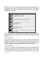
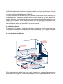
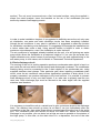
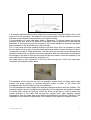
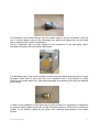
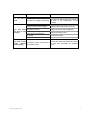
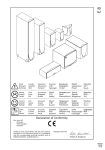
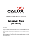
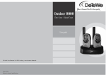
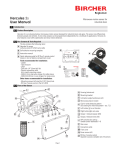
USER’S MANUAL
IZY
www.thermowellmarine.com
CONTENTS
1. Preface…………………………………………………………………………………………………….
pag. 3
2. Safety consideration…………………………………………………….………………………………… pag. 3
3. Unpacking the unit ……………………………………………………………………………………….. pag. 3
4. Testing……………………………………………………………………………………………………… pag. 4
5. How does it work ……..…………………………………………………………………………………… pag. 4
6. Installation diagram ……………..……………………………………………………………………….. pag. 5
6.1 Locate the air conditioner ………………………………….........…………………………………….. pag. 5
6.2 Drain discharge circuit………………...........………………………………………………………….. pag. 6
6.3 Air distribution circuit …………………………………………………………………………………… pag. 7
6.4 Sea water circuit ………………………………….……………………………………………………… pag. 7
7. Power supply ….……..…………………………………………………………………………………… pag. 10
8. Start-up ………..……..…………………………………………………………………………………… pag. 10
9. Maintenance ……..…………………………………………………………………………………….…
pag. 10
10. Troubleshooting …..……………………………………………………………………………………… pag. 11
User’s_manual_ENG_rev.06-09
2
1. Preface
Dear ship-owner,
congratulations on your purchase of this marine air conditioning system, which will assure
high comfort levels in your boat.
Thermowell marine air conditioners are efficient, powerful, compact and affordable units.
You’ll be satisfied by its advanced performances and latest technology.
Before starting installation it is strongly recommended to read this manual, which is also
basic and integrant part of the air conditioner, carefully and completely, because it
provides important information to ensure proper installation, operation and maintenance of
the unit and to get the best performance from the unit.
Improper installation or operating procedures may cause unsatisfactory performances and
/ or premature failure in the unit and / or the boat. This A/C unit is to be used only for the
purposes for which it has been designed and manufactured. If used in other ways, bad
functioning or damages caused to people and/or things are not responsibility of the
Manufacturer.
Before starting with the installation you should assure that the unit has been purchased
from an authorized Skipper dealer/distributor, the cartons contain all the items checked
into the packing list, the warranty certificate supplied with the unit is filled out correctly.
In case of any bad functioning during operation, please refer to the “Troubleshooting”
section in this manual. If the problem persists, please contact your authorized
dealer/distributor.
2. Safety consideration
• Turn the main power source off when servicing, when not using the unit for long time or
in case of failure.
• Do not turn on the air conditioner if the filters are not installed, in order to prevent dust
and dirt to settle on it.
• A performance drop may occur due to blocking the airflow of the unit by obstacles to the
air flowing in or out the air conditioner (in the range of 1 meter in front or above it).
• Do not operate the air conditioner in cooling mode while using any heating device inside
the cabin.
• Do not allow direct sunlight to enter the cabin while operating the unit, nor expose the
unit or the remote control to direct sunlight.
• Avoid the unit working when the boat is veering or with rough sea: the excessive lateral
or longitudinal inclination of the boat could cause the loss of water from the condensate
pan and the blockage or breaking of the compressors due to the non-circulation of
lubricating oil.
• Avoid the unit working while the in and out flow of the air is even partially obstructed; on
the contrary the electrical heater could damage itself irreparably.
• Never install the unit in the bilge or engine room
• Always follow safety labels put on the air conditioner.
• Check that the power supplied by the generator is sufficiently higher than the power
required by the unit for operating.
3. Unpacking the unit
When the unit is received, all items should be carefully checked against the following
User’s_manual_ENG_rev.06-09
3
packing list to ensure all cartons have been received and there are no damages. If there is
some shipping damage, the carrier should make the proper notation on the delivery receipt
acknowledging the damage. It is necessary to send to Thermowell a photographic
documentation of the damages within 10 days from the receiving of the unit, otherwise the
claim will not be accepted.
Q.ty
1
1
2,5 m
1
2
1
3m
1
1
2
1
1
1
6
1,5 m
1,5 m
4
1
1
1
1
Description
Self contained IZY air conditioner
Electronic board with remote controller
Flexible insulated duct diam. 100 mm
Round PVC air supply grille diam. 100 mm
PVC hose clamps for air duct 400x8 mm
PVC inlet air grille 300x300 mm
PVC tube with incorporated steel spiral int. diam. 18 mm
Sea water strainer
Male hose connector 1/2" x 18
Female hose connector 1/2" x 18
Female-female ball valve 1/2"
Brass sea intake 1/2"
Brass sea water drainage nozzle 1/2" x 19 mm
Inox steel hose clamps for water pipe diam 17-32 mm
Condensing water evacuation pipe 16x19 mm
Power supply electrical cable
Inox steel bracket
Installation, use and maintenance manual IZY air conditioner
Installation, use and maintenance manual remote controller COMEDE 1
Wiring scheme
Warranty certificate
It is important to handle the unit upright at all times. If the unit is not upright when received,
set it upright and wait until 24 hours before start it. Deeply inspect refrigerant copper pipes
inside the unit looking for fractures. Evidence of refrigerant oil is indicative of broken
refrigerant pipes.
4. Factory inspection
Thermowell tests and inspects all the units in its factory, according to accurate internal
standards. Each performance test carried out on the unit is possible only if the same
conditions are reproduced and maintained (charge consistency, constant evaporation and
condensing temperature, water and air temperatures, quality and tolerance of the
measuring instruments). It is possible to check the units in their destination place only if
the same conditions of the plant are reproduced and kept for the necessary time.
5. How does it works
IZY marine air conditioner is available in cooling only (CO) and cooling/heating (EH)
versions. Cooling operation is made by conventional vapour compression cycle (ecological
refrigerant gas R407C), through which is it possible to take heat from the cabin,
transferring to the sea water; in details, during summer operations the warm air of the
cabin is blowed by the centrifugal fun through the coil circulated by low temperature
User’s_manual_ENG_rev.06-09
4
refrigerating gas. In this way the air will be cooled before entering again the cabin. An
electrical pump properly dimensioned captures water from the sea and circulates it through
the cupronickel heat exchanger producing here gas condensation. Sea water temperature
is highly influencing the performance of the A/C.
In winter operations (EH models only) the air heating is made by an electric resistance put
inside the blower; compressor and sea water circulation pump do not work and the ball
valve on sea water circuit can be closed. In this way, unlike reversing cycle systems, the
heating operation is not affected by the lower sea water temperature reached during winter
season, thus obtaining 100% heating efficiency also with sea water temperature below
10°C. IZY operation mode is setted by the remote controller COMEDE1; more informations
about operations setting are described in the proper manual.
6. Installation diagram
Thermowell’s IZY marine air conditioning has been designed to operate over a wide range
of operative conditions, both for air and sea water temperature. If it is required to operate
the unit in particularly heavy conditions, pls contact Thermowell’s Technical Department.
6.1 Locate the air conditioner
B OCCH ET T A DI
IM M IS S IO NE
C IRCOL ARE
CI RCUL AR
VE NT IL AT IN G GR ILL E
CO M ANDO A P ARE T E
R EM O T E CO NT ROL LE R
T E LE CO M ANDO
R EM O T E CO NT ROL LE R
CO NDOT T A FL E SS IBI LE
F LE XIBL E D UCT
G RUP P O F RIGO
RE F RIGE RAT IN G UN IT
ARIA CABIN A
AI R F ROM CAB INE
S CARICO A M ARE
S EA W AT E R DRAIN AGE
NOZ Z L E
FIL TRO
S T RAINE R
S CARICO COND EN S A
C ONDE N S ING DRA INAGE
SA RACINE S CA
T AP
PRE S A M ARE
SE A WAT E R INT AKE
Each unit must be installed in a place easily accessible for maintenance reasons and
which allows the proper air circulation (at least 5-7 cm free space behind the return air
User’s_manual_ENG_rev.06-09
5
section). The unit must be secured onto a flat, horizontal surface, using the supplied Lshape inox steel brackets. Insert the brackets on the rim of the condensate pan and
secure by means of self-tapping screws.
In order to make installation simplest, it is suggested to definitely secure the unit only once
air distribution, sea water and drain discharge circuits has been completely installed.
Altough the air conditioner is very quiet in operation it is suggested to select the location
for installation considering noise emissions. It is suggested for example the installation into
a locker rather than under a bed. Using acoustic baffles is helpful in order to obtain
maximum noise absorption, even if the installation is under the berth.
The air conditioner is equipped, already installed into the unit, of a self priming sea water
pump which allows the installation at a maximum height of 1.6 mt over the sea water line.
Higher distances may cause losses of performance of the unit and malfunctioning in the
sea water pump; in such cases, ask for details to Thermowell Technical Department.
6.2 Drain discharge circuit
The running of the unit in cooling operation produces condensate water which is kept in a
pan inside the unit and which must be drained and discharged overboard. The condensate
draining tubing must be connected to the 2 drain nipples of the condensate pan, using
supplied stainless steel clamps. Take particular care when installing condensate drain
circuit, since the air conditioner can produce significative quantities of drain which, if not
properly evacuated, can produce damages to the boat furniture. It is possible to connect
drain discharge circuit to only one drain nipple; if so, take care to properly seal the non
used one. Drain discharge pipe must be secured to the drain nipple with the supplied
stainless steel brackets.
It is necessary to install the unit at a certain level to give a minimum slope to the discharge
hose. The draining hose should go down for at least 3 cm just immediately after the
connection to the pan, then going down without counterslopes along the line to the outlet
port. The overboard outlet port should be above the water line. Where the overboard
discharge is not possible, you can drain into a bilge as near as possible to the strainer of
the bilge pump. In this case, as the drain tube is in a depression, the end of the tube
User’s_manual_ENG_rev.06-09
6
shouldn’t be close to exhaust or to any source of poison gas. Do not put it in the bilge of
the engine room. Once drain discharge circuit installation has been ended, try its efficiency
filling the drain pan with water and verifying its flow.
6.3 Air distribution circuit
The inlet air grille must be installed as close as possibile to the air conditioner, near to the
floor, to allow an uninterrupted airflow to the unit. The inlet air grille can be placed opposite
respect to the coil, but in this case it is necessary to provide sufficient space around the
unit to assure the proper air flow.
The air supply grille should be installed as higher as possible to create the ideal air flow
into the ambient avoiding short cycling. It is important that the air flow is not oriented
directly towards the inlet air grille or the thermostat
The connection between the air blower and the circular air supply grille is made using the
flexible duct and the PVC hose clamps included inside the installation kit. The same
clamps could be used for the connection of the duct to eventual pipe derivation tee (max.1)
used for the air distribution inside contiguous ambient. For multiple outlet air grilles
installation, pls contact Thermowell Technical Department.
Take care of strictly tightening the clamps checking the absence of air leakages. The duct
should be positioned as straight as possible minimizing the number of the bend (each
bend reduces the air flow trough the duct of a certain quantity). The max length of the duct
should be 2.5 meter.
The air conditioner is provided directly from the factory with a filter placed in front of the air
return coil; during installation of the unit, consider for an easy accessibility to this filter for
cleaning and/or replacement (see Maintenance section of the present manual).
Sometimes it could happen that the return air must be ducted too; in such cases, please
contact Thermowell Technical Department.
6.4 Seawater circuit
For the seawater intake use:
1. the ½” brass sea intake supplied into the kit creating a dedicated water line
2. an existing seawater intake line not in use
Please refer to the following picture for the correct installation of the sea water intake.
User’s_manual_ENG_rev.06-09
7
It is strongly recommended to never intake the cooling water from the cooling circuit of the
engine or of the generator. The powerful self-priming pumps of these systems would win
the head of the seawater pump preventing its regular working.
If the installation of a new sea water intake is necessary, it must be placed as close as
possible to the keel and as far below the sea water level as possible thus reducing the
possibility of air entering the circuit (however it will not be dangerous since the sea water
pump installed on the air conditioner is self-priming).
The ½” ball valve should be installed directly on the ball valve, and it is necessary to close
the sea water circuit in case of general unit maintenance and/or strainer cleaning, so that it
is important to make it easily accessible. The ball valve can be keep closed during winter
operation which does not require sea water circulation. Ball valve should be closed before
the haulage of the boat: in this way the pump will be full of water. Check the opening of the
valve after the launching and before using the unit.
Sea water pipe is then connected to the ball valve through the ½”x20 mm male hose
connector and stainless steel clamps.
The seawater circuit must be as short as possible, without kinks or loops which could
prevent the pump priming or increase pressure drops of water in the circuit with
consequent loss of performance of the air conditioner.
The line between the water intake valve and the pump should be as short as possible. The
seawater strainer must be installed at the beginning of the intake line and properly situated
to provide easy access for cleaning. Check the arrow on the filter in order to assure the
correct direction of the water flow through the strainer itself. After cleaning, always
discharge air from the upper part of the strainer and check the right filling of the circuit. The
installation of the strainer is compulsory for the validity of the warranty in case of failure.
User’s_manual_ENG_rev.06-09
8
The seawater circuit should always rise, from water intake to the air conditioner. After the
unit, it can rise again or drop to the discharge part, which must always be over the water
line so that the circuit will be self bleeding.
The air conditioner has two hose fittings for the connection to the sea water circuit.
Seawater inlet and outlet are marked with labels.
The discharge side of the circuit should be made so that the water discharge will not cause
excessive noise both for your boat and your neighbours but in such position to easily
check for the proper water flow. Sea water discharge is connected to the pipe by stainless
steel clamps.
In case of new installation of sea water inlet or outlet or both, it is suggested to install them
on opposite sides respect to the keel, so that sea water coming out from the air conditioner
(hotter), is not directly sucked by the pump, thus reducing performance of the whole
system.
User’s_manual_ENG_rev.06-09
9
7. Power supply
Before any electrical operation it is necessary to disconnect the unit from power supply.
Electrical connections must be made by qualified technician or by people having
necessary knowledge.
For the electrical connection of the unit please refer to the wiring diagram supplied with the
unit.
Before electrical connections, verify that voltage, frequency and phase number available
are compatible with those labelled on the unit.
Locate the Speedy air conditioner as near as possibile to the current tap. If it is necessary
to increase length of the electric cable, it is recommended to make use of a cable having a
proper section and insulation according to the effective distance between the air
conditioner and the general electric board.
To prevent a possible electrical shock which could result in serious injury or death, always
ground the system.
A circuit breaker is always required (16 A for 9.000 BTU/h model, 20 A for 13.000 BTU/h
model).
8. Start-up
Before servicing the unit it is strongly suggested to check all the electrical and seawater
circuit connections.
Cooling mode operation:
1. Open the ball valve on the sea water circuit
2. Turn on the circuit breaker to the air conditioner
3. Turn on the air conditioner from the ON/OFF button on the wall mounted or remote
controller
4. Set the desired temperature to a lower value than the cabin temperature using the
TEMP buttons (arrow up to increase temperature, arrow down to decrease)
5. Check for the proper sea water flow by the sea water discharge or the strainer.
Heating mode operation
6. In heating mode is not required to open the ball valve
7. Turn on the circuit breaker to the air conditioner
8. Turn on the air conditioner from the ON/OFF button on the wall mounted or remote
controller
9. Set the desired temperature to a higher value than the cabin temperature using the
TEMP buttons (arrow up to increase temperature, arrow down to decrease)
9. Maintenance
Air filter: keep the air filters always clean by removing and washing them twice a month,
or at least at the beginning of cold/hot season. It must replace once in a year.
Drain discharge: Check periodically (3-4 times in a year) that the condensate discharges
are not clogged by dirtiness or other.
Sea water strainer: The seawater strainer installed on seawater pump intake requires to
be checked and cleaned periodically. This strainer is absolutely necessary as it prevents
the seawater pump and circuit to be clogged by dirty particles. There is not a fixed rule to
determine the periodicity of strainer maintenance, which depends on the number of
running hours and on the level of water pollution. In cool mode a reduced water flow
User’s_manual_ENG_rev.06-09
10
reduces the efficiency and eventually causes a unit shutdown. If the unit is used in the
harbours when there is backwash or strong wind there could be an intake of dirty particles
with following obstruction of the strainer.
Copper-nickel heat exchanger: Keep the copper-nickel heat exchanger circuit (sea water
circuit) always clean, washing it with proper products once every two years. This operation
has to be carried out in preference by a qualified r technician.
Refrigerant charge: each IZY unit is factory refrigerant charged (R407C) and tested.
Refrigerant charge should not need adjustment for all the life of the air conditioner. Only in
case of circuit broken or other leakage it needs to be recharged, but only once the failure
has been detected and repaired.Each operation on refrigerant circuit, as well as cleaning,
void and recharging operations must be made exclusively by qualified technicians.
Electrical system: all electrical components must be kept clean and dry. Check
periodically for electrical leaks, which, if detected, must be immediately eliminated.
Winterizing the system: when freezing temperature are expected, it is necessary to drain
all the water from the condenser, the sea water pump, the strainers and the connection
tubing. In details:
a) close the seawater intake;
b) remove the condensing unit inlet water hose;
c) clean the strainer and drain completely the water inside it and inside the pump.
If the boat must be on land for more than 30 days, allow all water to drain from the circuit
to avoid corrosion due to the stagnation and let fresh water flow for some minutes.
Remember to discharge the circuit when launching for the connection of the pump.
10. Troubleshooting
In case of failure, the COMEDE1 remote controller can stop unit operation, listing by an
alarm code the problem occurred. For more details on this feature, read carefully the
pertinent COMEDE1 user’s manual. Most common failure are listed in the table below.
User’s_manual_ENG_rev.06-09
11
Problem
Possible reasons
Solutions
The circuit braker is off
Turn circuit braker on
The unit doesn’t
If it is too low, ask the person in charge of
work
The input line voltage is insufficient the dock or the manufacturer of the
generator
Dispersion of heat
Close all the windows
Air filters of the unit are clogged
Rinse the filters with water and air dry
The unit does Temperature setting
Change the set point of temperature
not cool or heat
The setting of the operation mode is
properly
Change the setting mode
wrong (for ex. FAN or DRY)
Fan speed
Increase fan speed
Heat sources
Remove all heat sources
Remove and clean the strainer and check
The unit or the
The strainer is dirty or there is air in
the inlet duct; discharge the seawater
pump
doesn’t
the seawater circuit
pump
work properly
User’s_manual_ENG_rev.06-09
12
Technical information in this manual are not binding.
Thermowell in his pursuit of a policy of constant development
and upgrading of the manual may make
any modifications without prior notice
Thermowell
Sede Legale
Via Monte San Michele, 26
73055 Racale (LE) – Italy
Sede operativa
Via Olanda – Zona Industriale
73100 Lecce – Italy
Tel +39 0832 300214
Fax +39 0832 300214
[email protected]
[email protected]
www.thermowellmarine.com
User’s_manual_ENG_rev.06-09
13