1
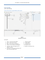
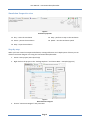
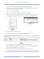
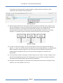
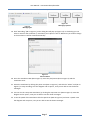
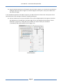
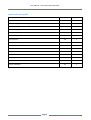
GROUP 2
User Manual
Interaction Editor/Recorder
Daniel Schiermer 062415, Jesper Kristensen 062397, Philip Back 062398,
Abbas Amini 062422 and Henrik Mynderup 062373
21-12-2007
User Manual – Interaction Editor/Recorder
December 21, 2007
Table of Contents
CASETool ............................................................................................................................................................ 2
Component Definition ................................................................................................................................... 2
Deployment Editor ........................................................................................................................................ 2
Simulation...................................................................................................................................................... 2
Interaction Editor/Recorder .......................................................................................................................... 2
Dashboard ..................................................................................................................................................... 2
User manual....................................................................................................................................................... 3
View of the Interaction Editor/Recorder ....................................................................................................... 3
Simulation Properties view............................................................................................................................ 4
Step-by-step .................................................................................................................................................. 4
Quick reference guide ................................................................................................................................... 9
Table of figures
Figure 1 Explanation of the editor ..................................................................................................................... 3
Figure 2 Simulation properties .......................................................................................................................... 4
Figure 3 New interaction diagram ..................................................................................................................... 4
Figure 4 Load Resource ..................................................................................................................................... 5
Figure 5 Choose Resource ................................................................................................................................. 5
Figure 6 Properties view .................................................................................................................................... 5
Figure 7 Lifeline properties................................................................................................................................ 6
Figure 8 Unnamed message .............................................................................................................................. 6
Figure 9 Message types ..................................................................................................................................... 7
Figure 10 Message properties ........................................................................................................................... 7
Figure 11 Save simulation.................................................................................................................................. 7
Figure 12 Create simulation .............................................................................................................................. 8
Page 1
User Manual – Interaction Editor/Recorder
December 21, 2007
CASETool
Author: Daniel & Philip
This CASETool is used as a helpful tool to design embedded systems. All its different units help in different
ways. The main focus of this user manual is the interaction Editor/Recorder.
The complete program consists of 5 units; a component editor (and message definition), deployment
editor, simulator, interaction Editor/Recorder and a dashboard. In the component editor you define your
components, and messages (see below). The deployment editor is used to define messages between
components (see below). The interaction Editor/Recorder is used to draw and record interaction diagrams
of the designed embedded system (see below). The dashboard is showing the embedded system visually.
The simulator simulates the messages sent between the components.
Component Definition
When designing embedded systems you need some components. The components can be a controller, a
software component or a hardware component. Each component needs a port definition and an
automaton with a definition of the different states and transitions of the components.
Since the components are supposed to send messages to each other, you need a message definition. The
message definition defines the messages to be used.
Such component definition and message definition can be created using the component editor.
Deployment Editor
When you have defined the components and their ports, and of course the messages, you need at
deployment to state which messages are going between which components. For this you will use the
deployment editor. This editor is also used to define which messages are using which ports.
Simulation
The simulator uses a deployment and sends the defined messages between the components. This is helpful
to see how the messages are defined between the components.
Interaction Editor/Recorder
This part is used to draw an interaction diagram of the deployment you have made. First you can draw the
interaction diagram as you would predict the messages to be sent, and then you can record from the
simulation of the deployment. It is not necessary to draw your own diagram first. The alternative is to start
recording right away.
Dashboard
The dashboard shows visually how the different components reacts to the messages they receive. This way
you can see that the state changes due to a message sent from one component to another.
Page 2
User Manual – Interaction Editor/Recorder
December 21, 2007
User manual
Author: Daniel & Philip
View of the Interaction Editor/Recorder
Figure 1
Explanation of the editor
Description
1.
2.
3.
4.
5.
Select – select the drawn objects
Zoom – zooms on the screen
Note – insert a note in the diagram
Lifeline – draw a lifeline on the diagram
Message – draw a message from one
lifeline to another
6. Recording – record a given simulation and
get the send messages drawn
Page 3
7.
8.
9.
10.
11.
Name on lifeline
Lifeline object
Simulation view
Properties view
Options in simulation view
User Manual – Interaction Editor/Recorder
December 21, 2007
Simulation Properties view
Figure 2
Simulation properties
12. Play – starts the simulation
15. Step – performs a step on the simulation
13. Pause – pauses the simulation
16. Speed – sets the simulation speed
14. Stop – stops the simulation
Step-by-step
When you have created a component definition, message definition and a deployment of those you can
draw an interaction diagram of it using the Interaction Editor/Recorder.
1. Create a new project (see Eclipse help)
2. Right-click on the project in the “Package Explorer” and choose New -> Example (Figure 3)
Figure 3
New interaction diagram
3. Choose “Interaction Diagram” and press Next
Page 4
User Manual – Interaction Editor/Recorder
December 21, 2007
4. Name your interaction diagram <name>.interaction_diagram and press Next
5. You have to create an interaction for the diagram. This is done automatically, you just have to
name it <name>.interaction and then press Finish
6. Open the Interaction Editor/Recorder
7. Right-click on the field of the editor and choose “Load Resource” (Figure 4)
8. Browse your file system or your workspace and choose your deployment (Figure 5). Now your
message definition should be loaded as well. If not do the same for your message definition
Figure 5
Choose Resource
Figure 4
Load Resource
9. Select the properties view (#10 on Figure 1)
10. You will now be able to choose one of the loaded deployments (Figure 6)
Figure 6
Properties view
11. Choose the deployment that you would like to draw an interaction diagram of
12. Create a lifeline by choosing “Lifeline” (#4 on Figure 1) and left-click on the editor field. A lifeline
will be drawn and automatically sized and positioned.
13. Left-click on the visual lifeline and choose the properties view (#10 on Figure 1).
14. In the properties view (#10 on Figure 1) you can choose which component (in the deployment) the
selected lifeline should represent. When you have chosen one of the components, then the name
Page 5
User Manual – Interaction Editor/Recorder
December 21, 2007
of the lifeline will automatically be updated (Figure 7). Repeat step 12 to step 14 for those
components you would like to be represented
Figure 7
Lifeline properties
15. Draw messages between the components (lifelines) by selecting “Message” (#5 on Figure 1) and
left-click (hold down) on the source lifeline, and drag the mouse to the target lifeline and release
the left mouse button. A message (arrow) will be drawn between the two lifelines and
automatically be positioned. A name-tag for the message will appear with the text “unnamed
message”. It is possible to choose the same component (lifeline) as source and target.
Figure 8
Unnamed message
16. In order to name the messages, click on the message and choose the properties view (#10 on
Figure 1). In “type” you can select which message, from your message definition, you would like the
drawn message to represent (Figure 9). The name-tag on the message will automatically be
updated (Figure 10). Repeat step 15 to step 16 for all the messages you would like to be
represented.
17. If you would like to delete a message or a lifeline simply use the “Select” tool (#1 on Figure 1) and
select the message/lifeline and press the delete button on your keyboard. Messages attached to
the lifelines that is being deleted, will automatically be deleted.
18. Saving the interaction diagram is simply done by pressing CTRL+S (shortcut) or closing the editor
and press “yes” when asked to save or not.
Page 6
User Manual – Interaction Editor/Recorder
December 21, 2007
Figure 10
Message properties
Figure 9
Message types
19. Click ”Recording” (#6 on Figure 1), and a dialog box will pop-op (Figure 11). In this dialog you can
select a name for the simulation (*.simulation) and a place to save it. Whenever you make a change
in the simulation it will be saved automatically.
Figure 11
Save simulation
20. Go to the simulation view (#9 on Figure 1). Press the play button (#12 on Figure 2) and the
simulation starts.
21. Pause the simulation by clicking the pause-icon (#13 on Figure 2), and click the “Select”-tool (#1 on
Figure 1) to stop recording, save the diagram and re-open it, now you are able to see the drawn
messages.
22. You can also do a step-wise simulation, by clicking the step-wise-icon (#15 on Figure 2). Save the
diagram and re-open it, now you are able to see the drawn messages.
23. To set the speed of the simulation click the speed-icon (#16 on Figure 2) and enter a speed. Save
the diagram and re-open it, now you are able to see the drawn messages.
Page 7
User Manual – Interaction Editor/Recorder
December 21, 2007
24. Stop the paused simulation by clicking the stop-icon (#14 on Figure 2) or continue the simulation by
clicking the play-icon (#12 on Figure 2). Save the diagram and re-open it, now you are able to see
the drawn messages.
In the simulation properties view (#10 on Figure 1) you will at all time be able to see a description of the
performed action, like starting a simulation, stopping, pausing etc.
25. There is another way to create a simulation. Go to your Package Explorer (see Figure 12) and find
the deployment you would like to simulate. Right-click on the deployment and choose “Create
Simulation” (Figure 12), a dialog will pop-up where you need to name your simulation
(*.simulation) and choose where to save it (Figure 11).
Figure 12
Create simulation
Page 8
User Manual – Interaction Editor/Recorder
December 21, 2007
Quick reference guide
Reference word
Step number :
Page number:
Add name (object) to a lifeline
14
5-6
Add name (object) to a message
16
6
8-10
5
Delete message/lifeline
17
6
Draw a lifeline
12
5
Draw a message
15
6
Load resource
7-8
5
New interaction diagram
1-5
4-5
New simulation
19 or 25
7 or 8
Pause simulation
21
7
Play simulation
20
7
Record simulation
19
7
Save an interaction diagram
18
6
Set simulation speed
23
7
Step in simulation
22
7
Choose deployment
Page 9